Install the PTX12008
This topic guides you through the steps to install the PTX12008 in a 19-inch wide four-post rack or in a cabinet that has a 19-inch wide four-post rack.
You can install the PTX12008 in a 19-inch wide four-post rack or in a cabinet that has a 19-inch wide four-post rack. The remainder of this topic uses rack to mean rack or cabinet.
Complete these prerequisites before you install the router:
-
Prepare the site for installation as described in Site and Electrical Guidelines.
-
Ensure that the site has adequate clearance for both airflow and hardware maintenance.
Figure 1: Clearance Requirements for PTX12008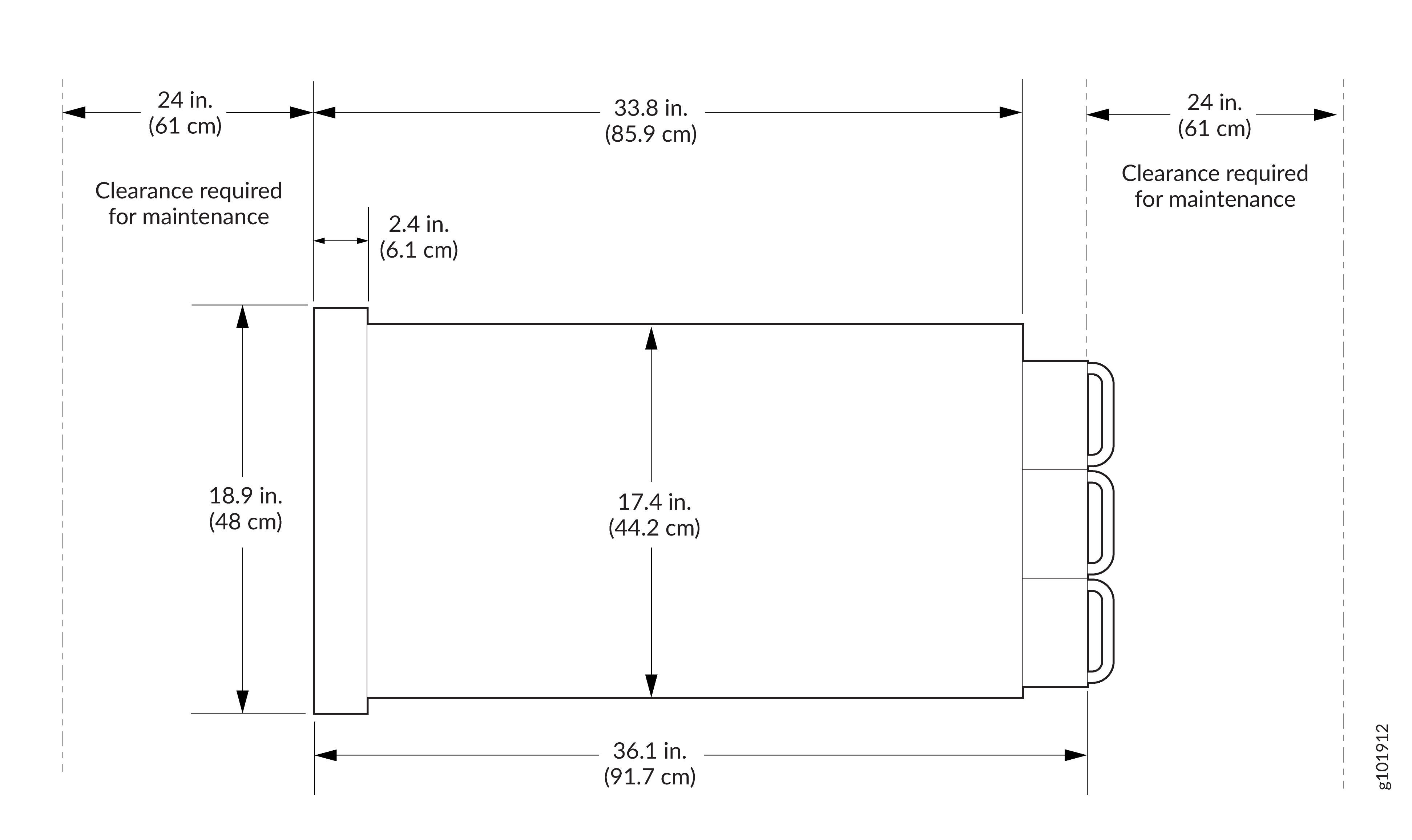
-
Unpack the router as described in Unpack the PTX12008.
Before mounting the router, a qualified technician must verify that the rack is strong enough to support the router's weight. Have the technician also verify that the rack has adequate support at the installation site.
If you are installing more than one router on a rack, install the first router at the bottom of the rack.
Do not install Flexible PIC Concentrators (FPCs) in the chassis until after you mount the chassis securely on a rack.
Install the PTX12008 in a Rack by Using the PTX12K-RMK Rack Mount Kit
You can install the PTX12008 in a 19-inch wide four-post rack or in a cabinet that has a 19-inch wide four-post rack by using the PTX12K-RMK rack mount kit or by using the PTX12K-RMK-EXT rack mount kit intended for heavy-duty use. This topic explains the procedure to install the PTX12008 by using the PTX12K-RMK rack mount kit. The remainder of this topic uses rack to mean rack or cabinet.
The PTX12K-RMK rack mount kit is provided by default. The PTX12K-RMK-EXT rack mount kit is separately orderable.
Before you install the PTX12008 in a rack, review the following:
-
Ensure that you understand how to prevent electrostatic discharge (ESD) damage. See Prevention of Electrostatic Discharge Damage.
-
Ensure that you know how to handle and store FPCs.
-
Have three persons available—two persons to push the router onto the mounting tray and a third person to align the router to the mounting tray.
-
Ensure that you have the following parts and tools available:
-
The PTX12K-RMK rack mount kit—provided
-
50 screws appropriate for your rack—not provided
-
A mechanical lift to mount the router—not provided
-
An ESD grounding strap—not provided
-
A Phillips (+) screwdriver, number 2—not provided
-
A screwdriver to attach screws to your rack—not provided
-
-
If Routing and Control Boards (RCBs), FPCs, power supply modules (PSMs), fan trays, or Switch Interface Boards (SIBs) are installed in the chassis, remove them. See:
To install the PTX12008 in a rack:
-
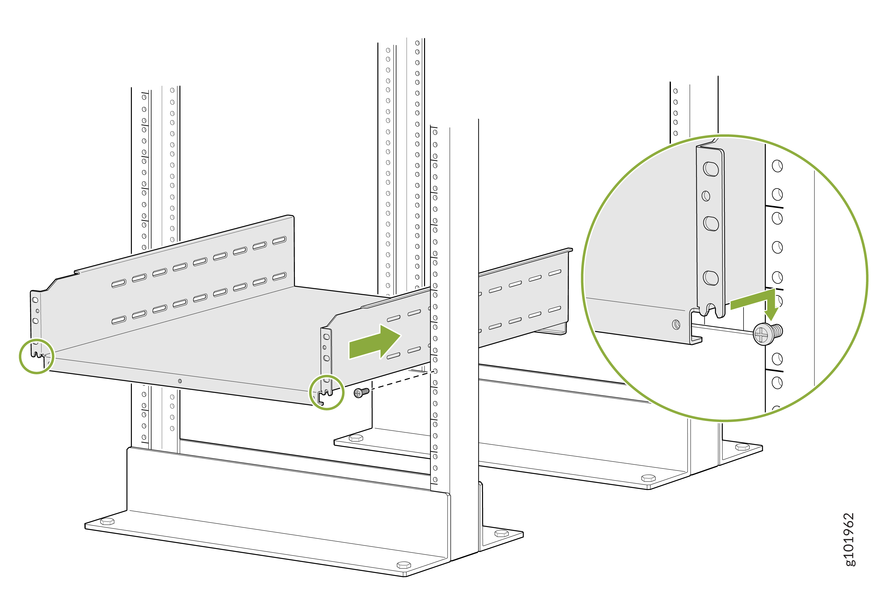
On the front of each front rack post, insert a screw appropriate for your
rack in the screw slot in the center of a rack unit, partially. Rest the
bottom slot of the mounting tray on the screws. The mounting tray extends
toward the center of the rack. Tighten the screws by using a
screwdriver.
-
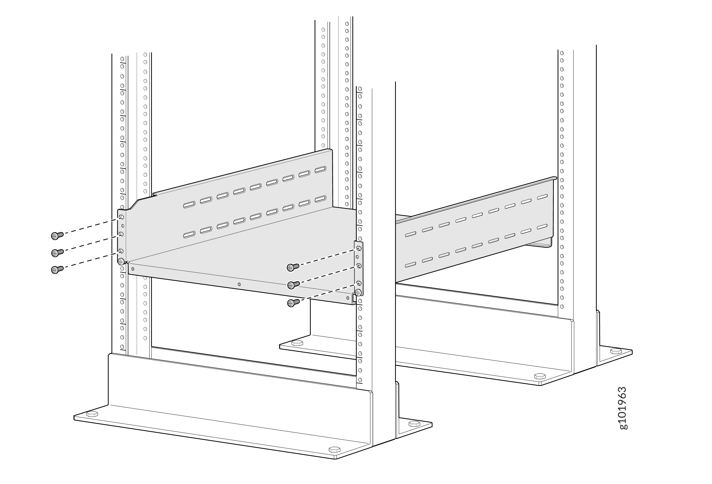
Attach the mounting tray to the front rack posts by using six screws
appropriate for your rack and a screwdriver.
-
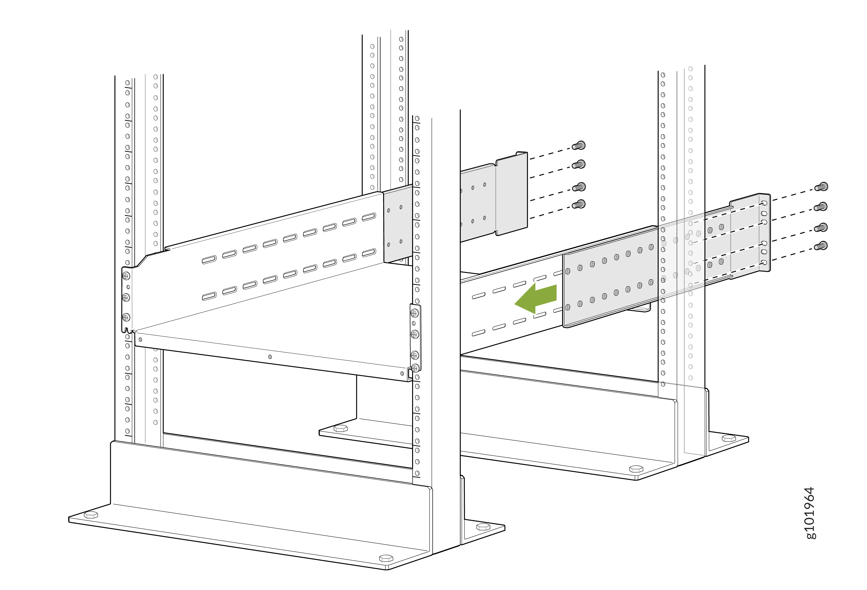
From the rear of the rack, slide the mounting tray brackets into the
grooves of the mounting tray. Attach the mounting tray brackets to the rear
rack posts by using four rack-mounting screws each appropriate for your rack
and a screwdriver.
-
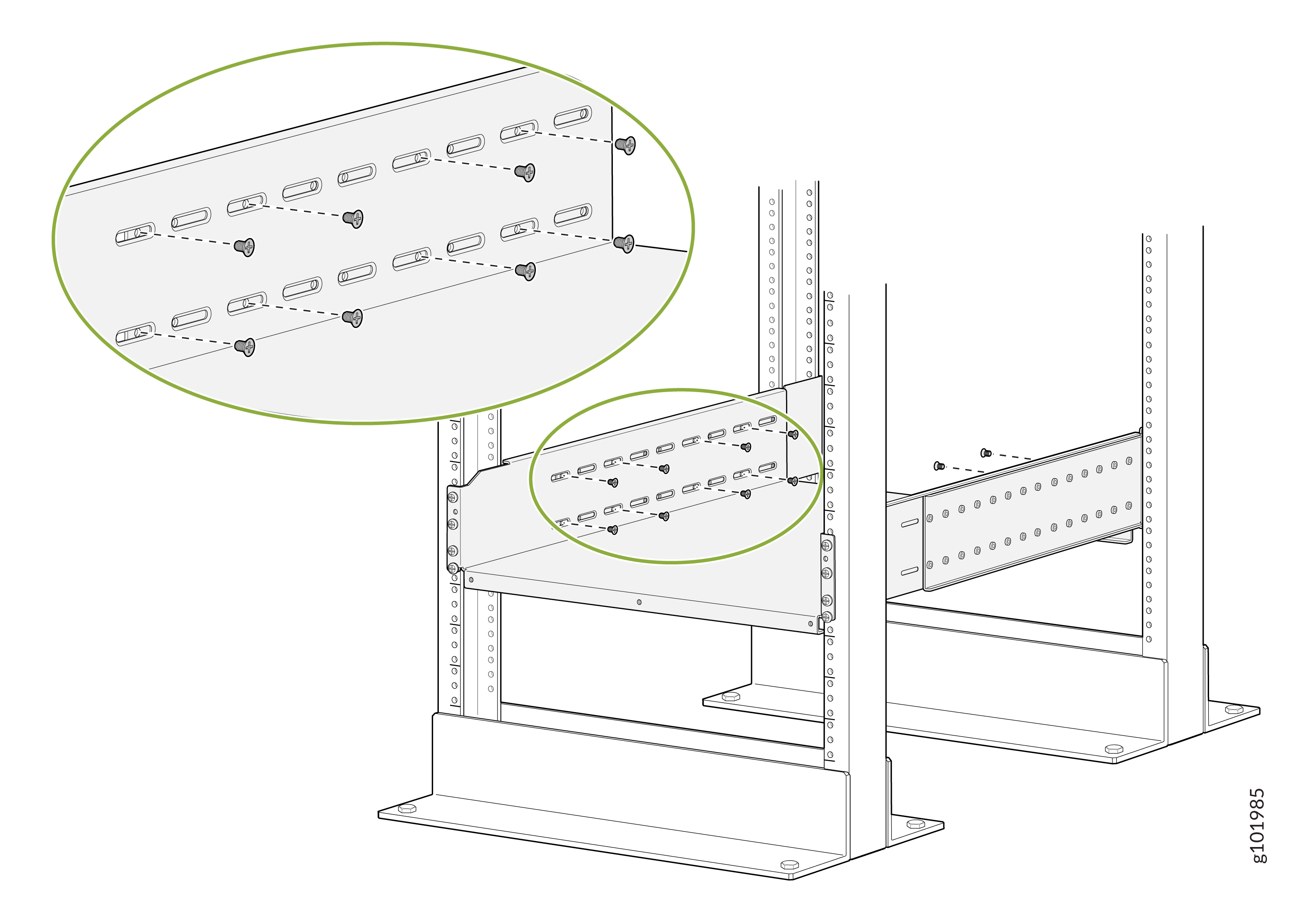
Attach the mounting tray brackets to the mounting tray with a minimum of 16
Phillips M4x8mm flat-head screws. Tighten the screws using a Phillips (+)
screwdriver, number 2.
Apply 18
lb⋅in (2 Nm) of torque to the screws. You can install up to 18 screws on
each side. We recommend that you install as many screws as possible.
-
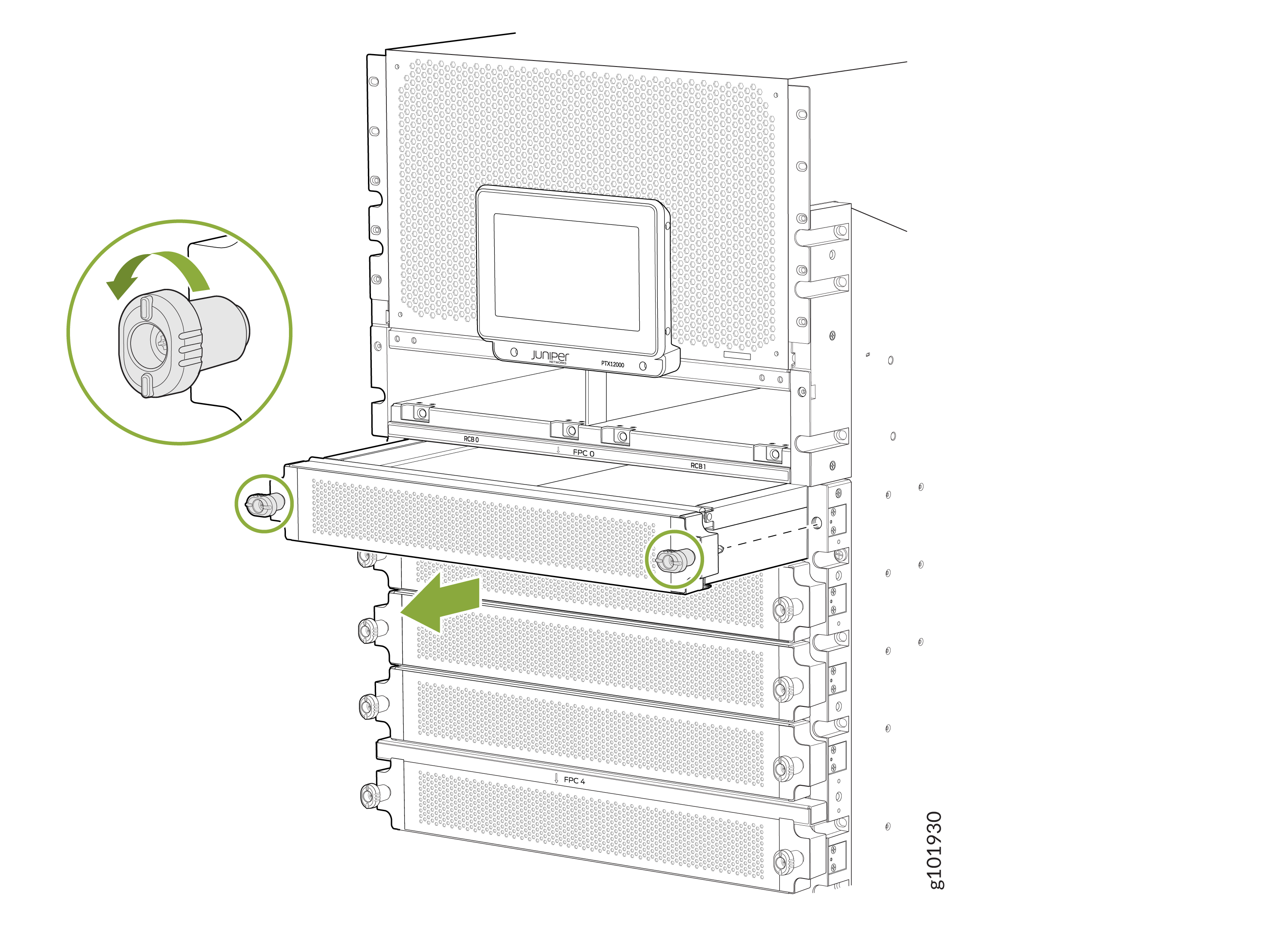
Remove each FPC slot cover from the router by grasping the handles, turning
them counterclockwise, and pulling the cover straight out. Store the
covers.
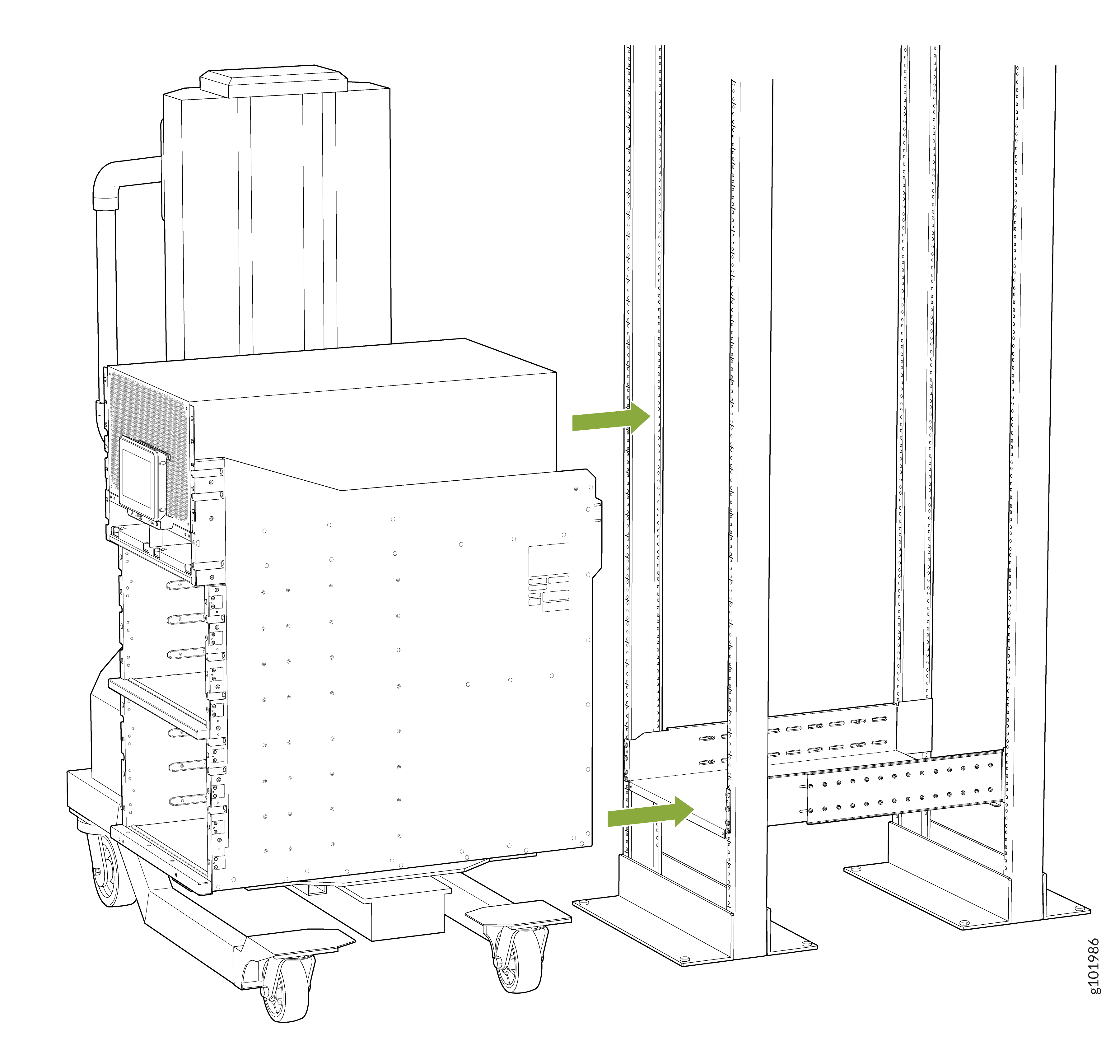
 Note: The router weighs 275 lb (124.7 kg) without any FRU installed. Because of the router's size and weight, we strongly recommend that you use a mechanical lift to mount the router.
 -
Using the lift, align the chassis in front of the rack and center it in
front of the mounting tray.
-
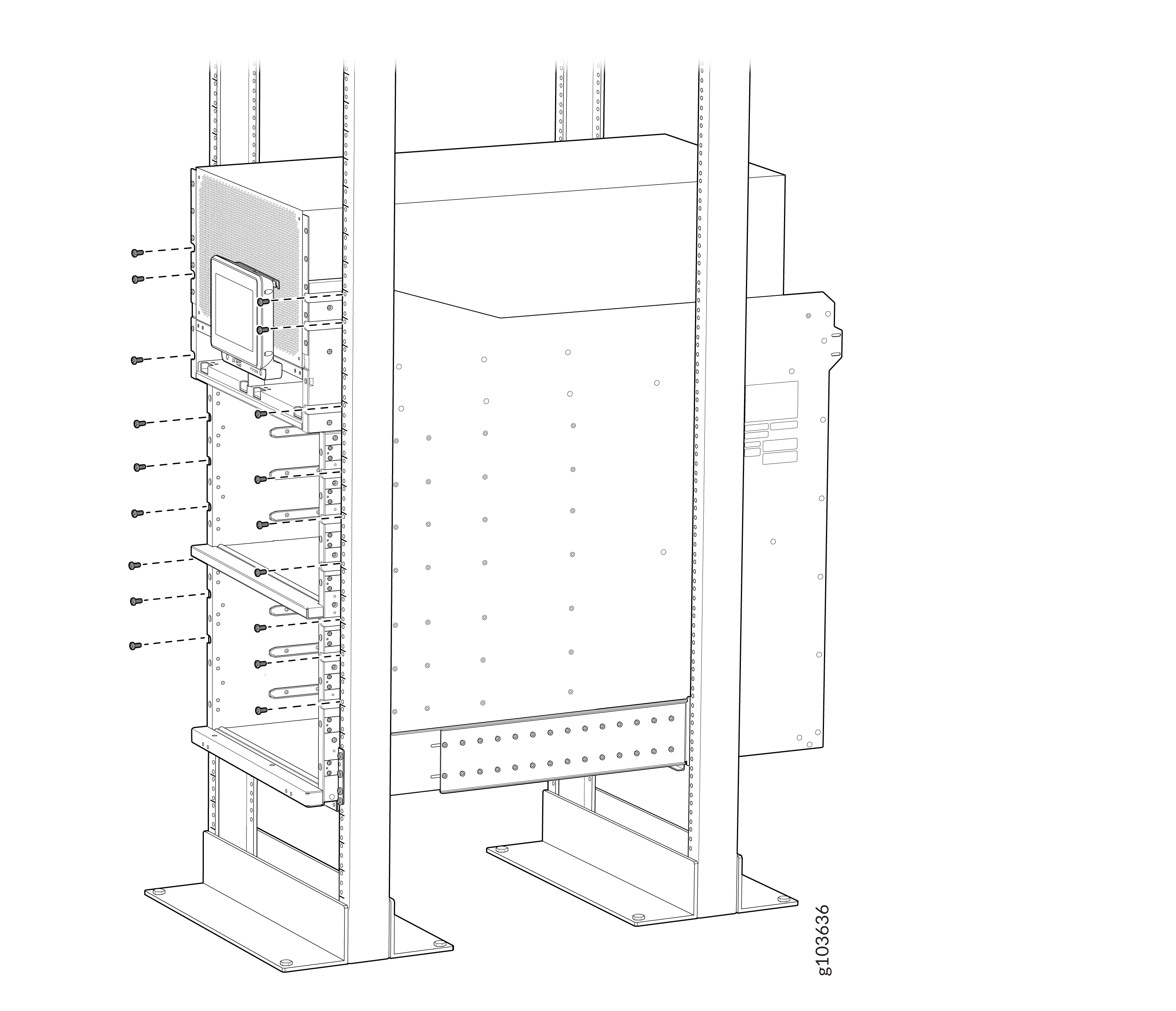
Attach the two chassis flanges to the front posts of the rack by using
rack-mounting screws appropriate for your rack and a screwdriver. You must
use nine rack-mounting screws for each chassis flange.
-
Attach the two
rear
side brackets to the rack by using rack-mounting screws
appropriate for your rack and a screwdriver. You must use eight
rack-mounting screws for each mounting bracket. Depending on the location of
the rack posts in relation to the chassis, you can attach the
rear
side brackets in two different orientations. Figure 2 shows the orientation of the
brackets when the chassis extends out of the rack posts. Figure 3 shows the orientation of the
brackets when the chassis is inside the rack posts.
Figure 2: Attach the Rear Side Brackets to the Rack When the Chassis Extends Out of the Rack Posts
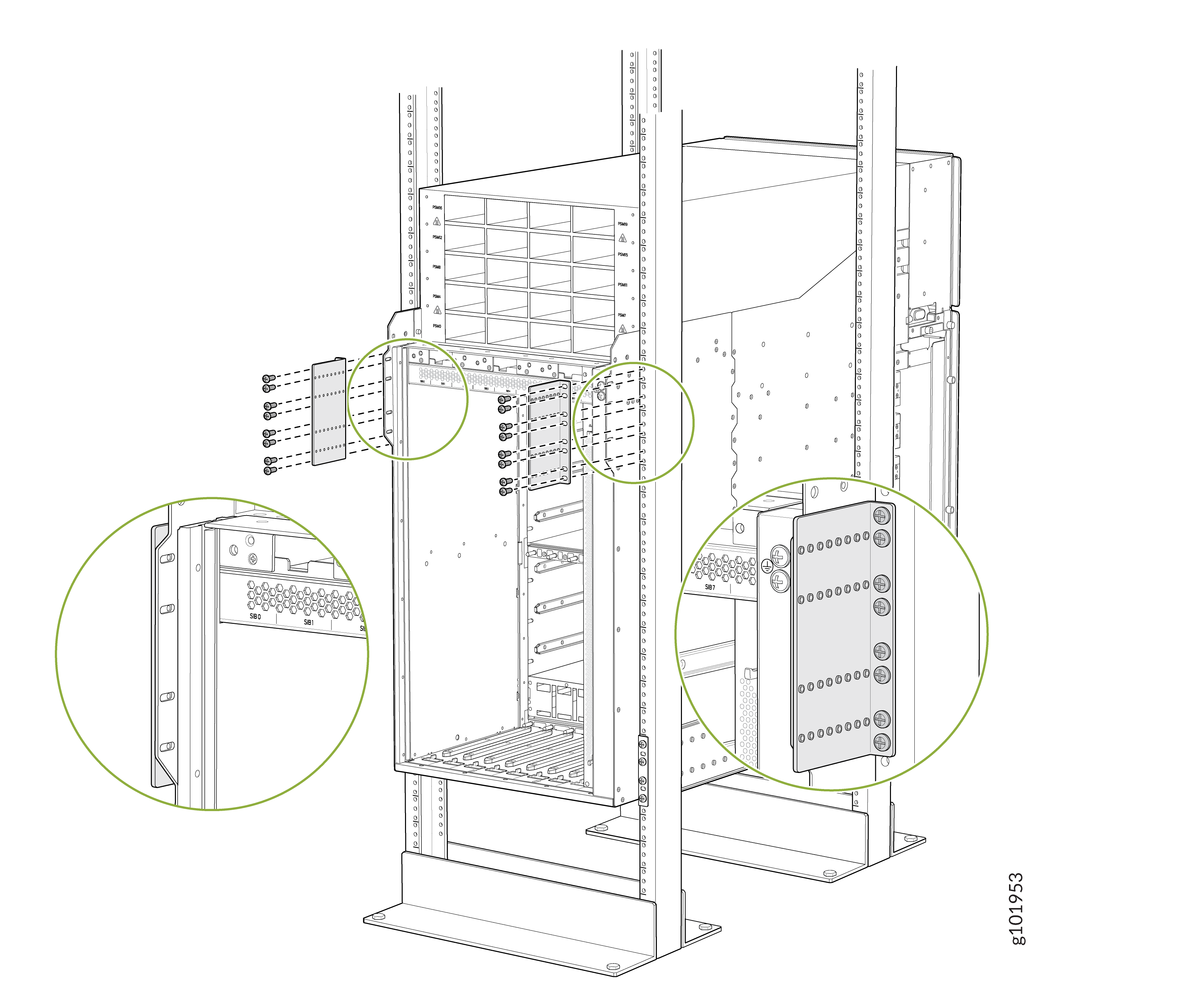 Figure 3: Attach the Rear Side Brackets to the Rack When the Chassis Is Inside the Rack Posts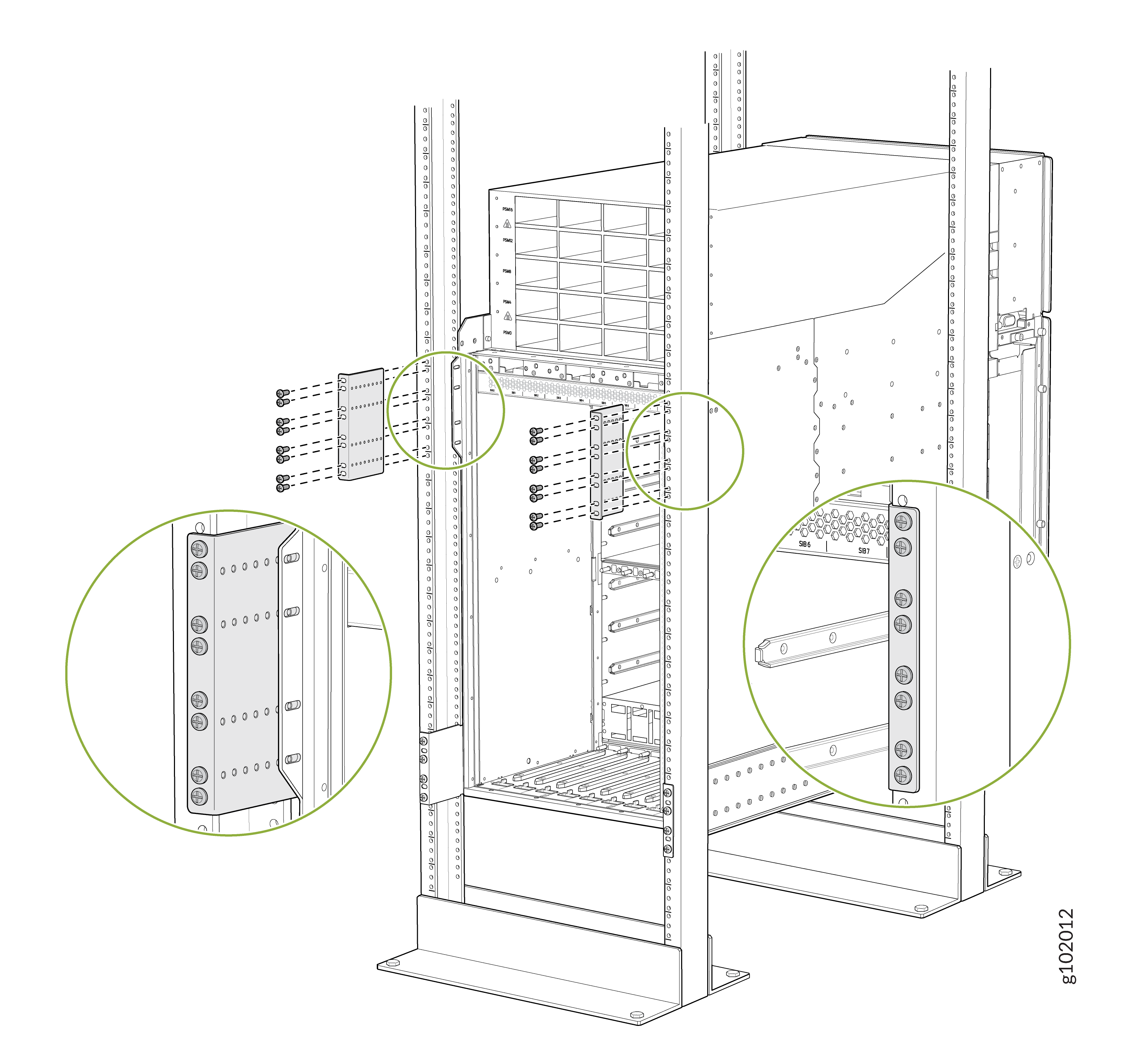
-
Attach the chassis to each
rear
side brackets by installing eight Phillips M4x8mm pan head
screws through each open flange hole and a screw slot on the
rack.
Tighten the screws using a Phillips (+) screwdriver, number 2. Apply 18
lb⋅in (2 Nm) of torque to the screws. Depending on the
location of the rack posts in relation to the chassis, you can use the rear
brackets in two different orientations. Figure 4 shows the orientation of the
brackets when the chassis extends out of the rack posts. Figure 5 shows the orientation of the
brackets when the chassis is inside the rack posts.
Figure 4: Attach the Chassis to the Rear Side Brackets When the Chassis Extends Out of the Rack Posts
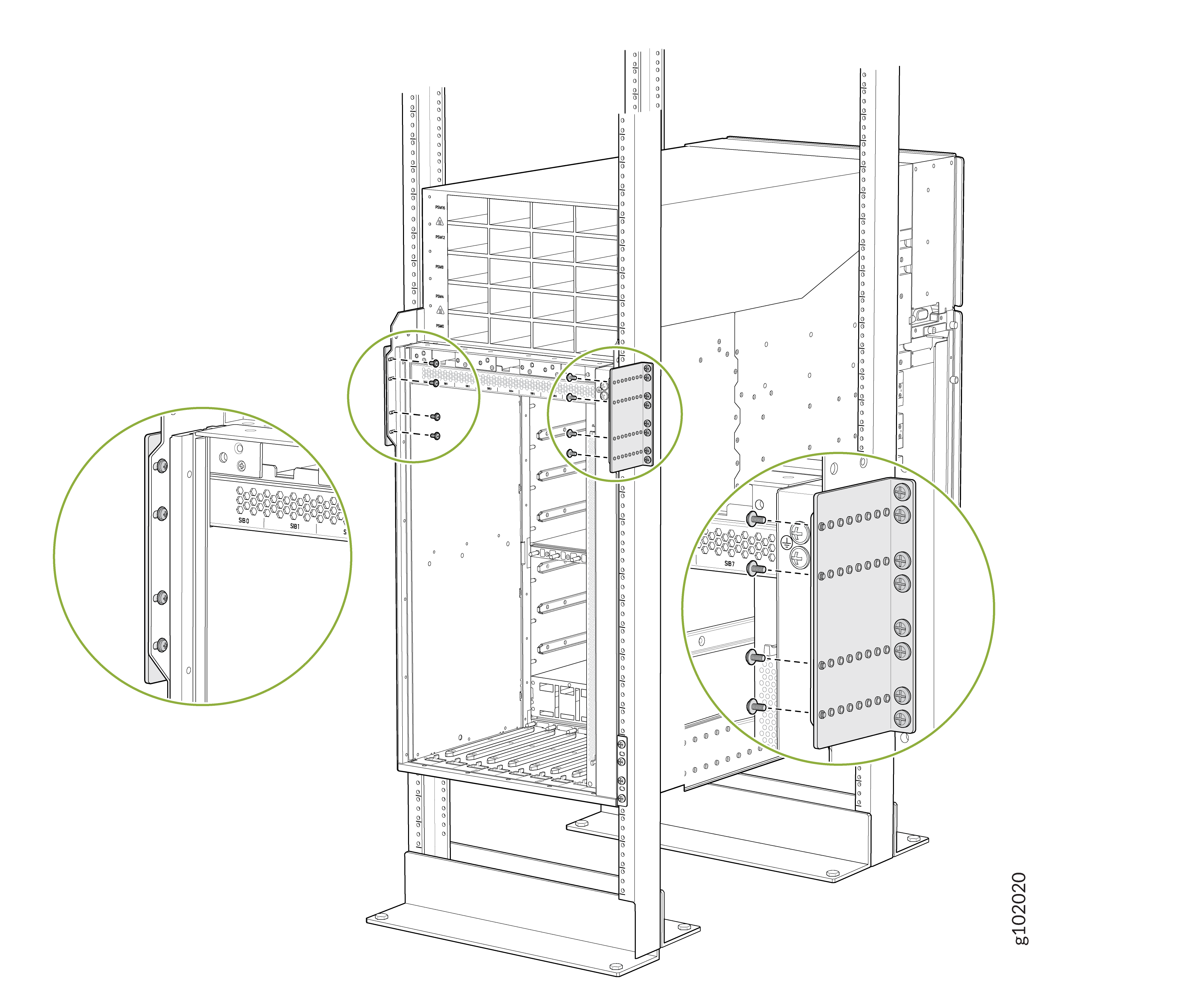 Figure 5: Attach the Chassis to the Rear Side Brackets When the Chassis Is Inside the Rack Posts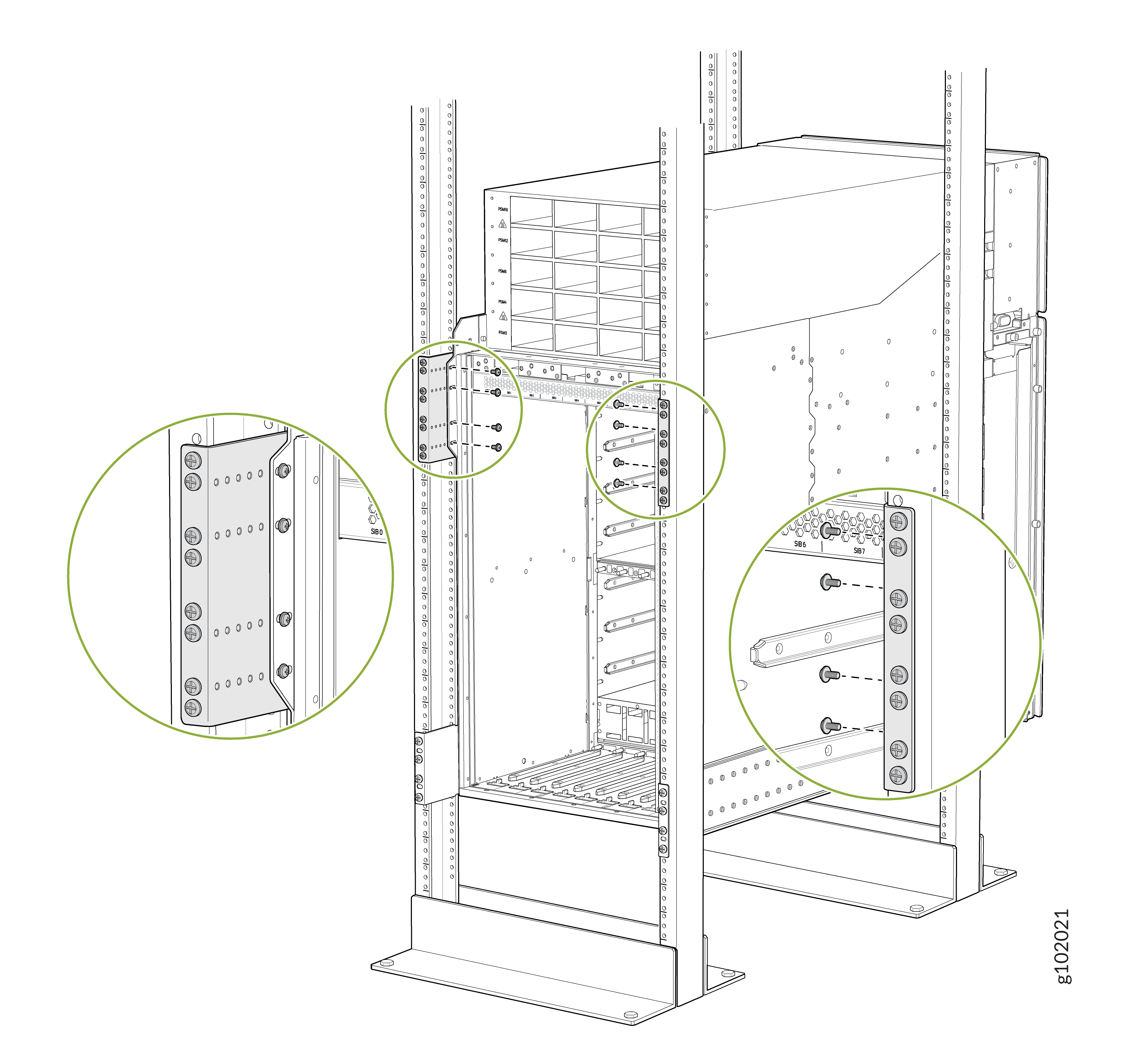
To install RCBs, FPCs, transceivers, PSMs, SIBs, or fan trays in the chassis, see:
Install the PTX12008 in a Rack by Using the PTX12K-RMK-EXT Rack Mount Kit
You can install the PTX12008 in a 19-inch wide four-post rack or in a cabinet that has a 19-inch wide four-post rack by using the PTX12K-RMK rack mount kit or by using the PTX12K-RMK-EXT rack mount kit intended for heavy-duty use. This topic explains the procedure to install the PTX12008 by using the PTX12K-RMK-EXT rack mount kit. The remainder of this topic uses rack to mean rack or cabinet.
The PTX12K-RMK rack mount kit is provided by default. The PTX12K-RMK-EXT rack mount kit is separately orderable.
Before you install the PTX12008 in a rack, review the following:
-
Ensure that you understand how to prevent electrostatic discharge (ESD) damage. See Prevention of Electrostatic Discharge Damage.
-
Ensure that you know how to handle and store FPCs.
-
Have three persons available—two persons to push the router onto the mounting tray and a third person to align the router to the mounting tray.
-
Ensure that you have the following parts and tools available:
-
The PTX12K-RMK-EXT rack mount kit (separately orderable)
-
66 screws appropriate for your rack—not provided
-
A mechanical lift to mount the router—not provided
-
An ESD grounding strap—not provided
-
A screwdriver to attach screws to your rack—not provided
-
A Phillips (+) screwdriver, number 2—not provided
-
-
If Routing and Control Boards (RCBs), FPCs, power supply modules (PSMs), fan trays, or Switch Interface Boards (SIBs) are installed in the chassis, remove them. See:
To install the PTX12008 in a rack:
-
On the rear of each rear rack post, insert a screw appropriate for your
rack in the lower position of the desired rack unit, partially. Rest the
bottom slot of the mounting tray rear support on the screws. The mounting
tray rear support extends toward the center of the rack. Tighten the screws
by using a screwdriver.

-
Attach the mounting tray rear support to the rear rack posts by using six
rack-mounting screws appropriate for your rack on each side and a
screwdriver.

-
On the front of each front rack post, insert a screw appropriate for your
rack in the lower position of the desired rack unit (same height location as
the first screws from 2),
partially. Rest the bottom slot of the front mounting tray on the screws.
The mounting tray extends toward the center of the rack and rests on top of
the mounting tray rear support. Tighten the screws by using a
screwdriver.

-
Attach the mounting tray to the front rack posts by using screws
appropriate for your rack and a screwdriver.

-
Attach the mounting tray to the mounting tray rear support with a minimum
of 18 Phillips 8-32x.375 flat-head screws on each side. Tighten the screws
using a Phillips (+) screwdriver, number 2.
Apply 15
lb⋅in (1.7 Nm) of torque. You can install up to 30 screws
on each side. We recommend that you install as many screws as
possible.


-
Remove each FPC slot cover from the router by grasping the handles, turning
them counterclockwise, and pulling the cover straight out. Store the
covers.
Note: The router weighs 275 lb (124.7 kg) without any FRU installed. Because of the router's size and weight, we strongly recommend that you use a mechanical lift to mount the router.
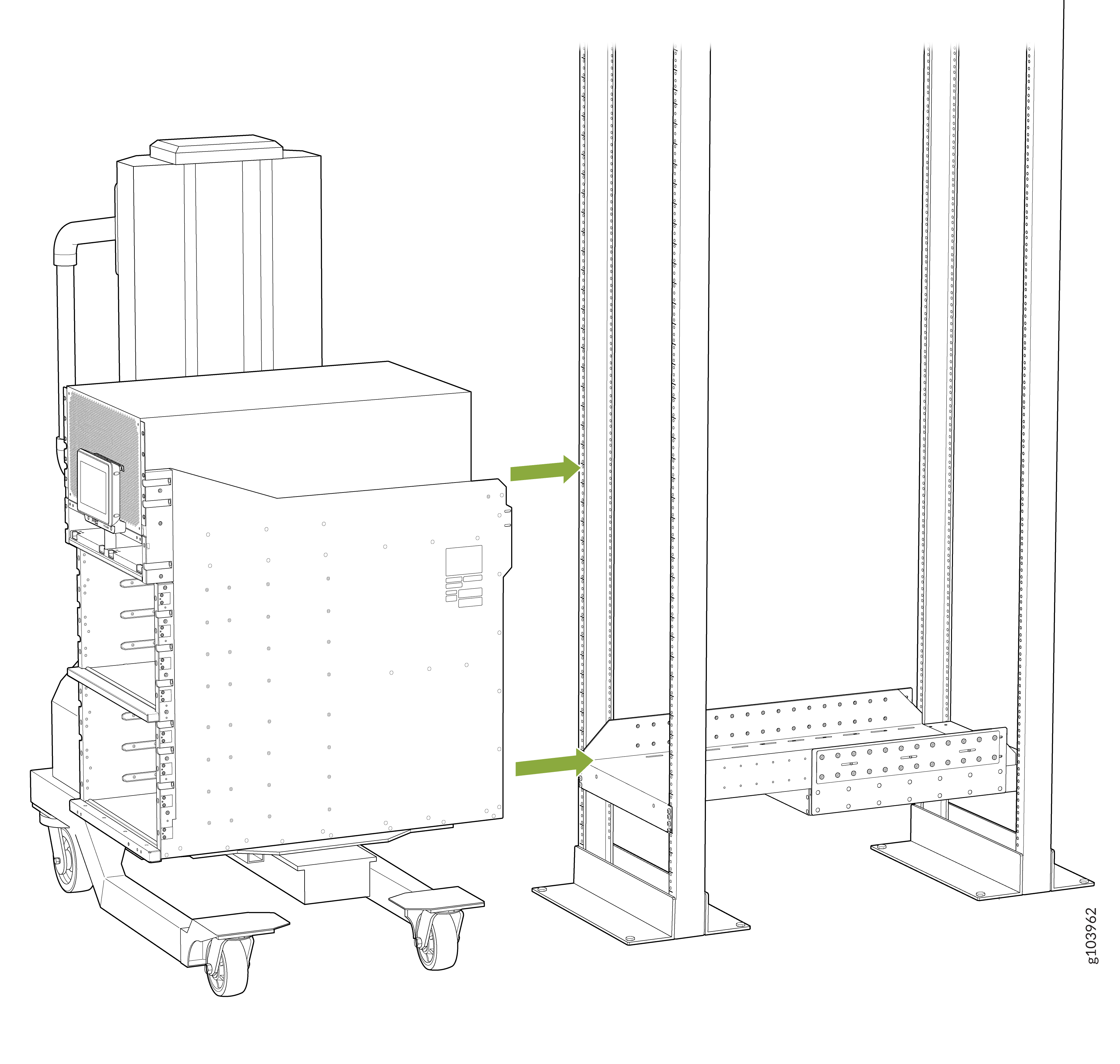
-
Using the lift, align the chassis in front of the rack and center it in
front of the mounting tray.
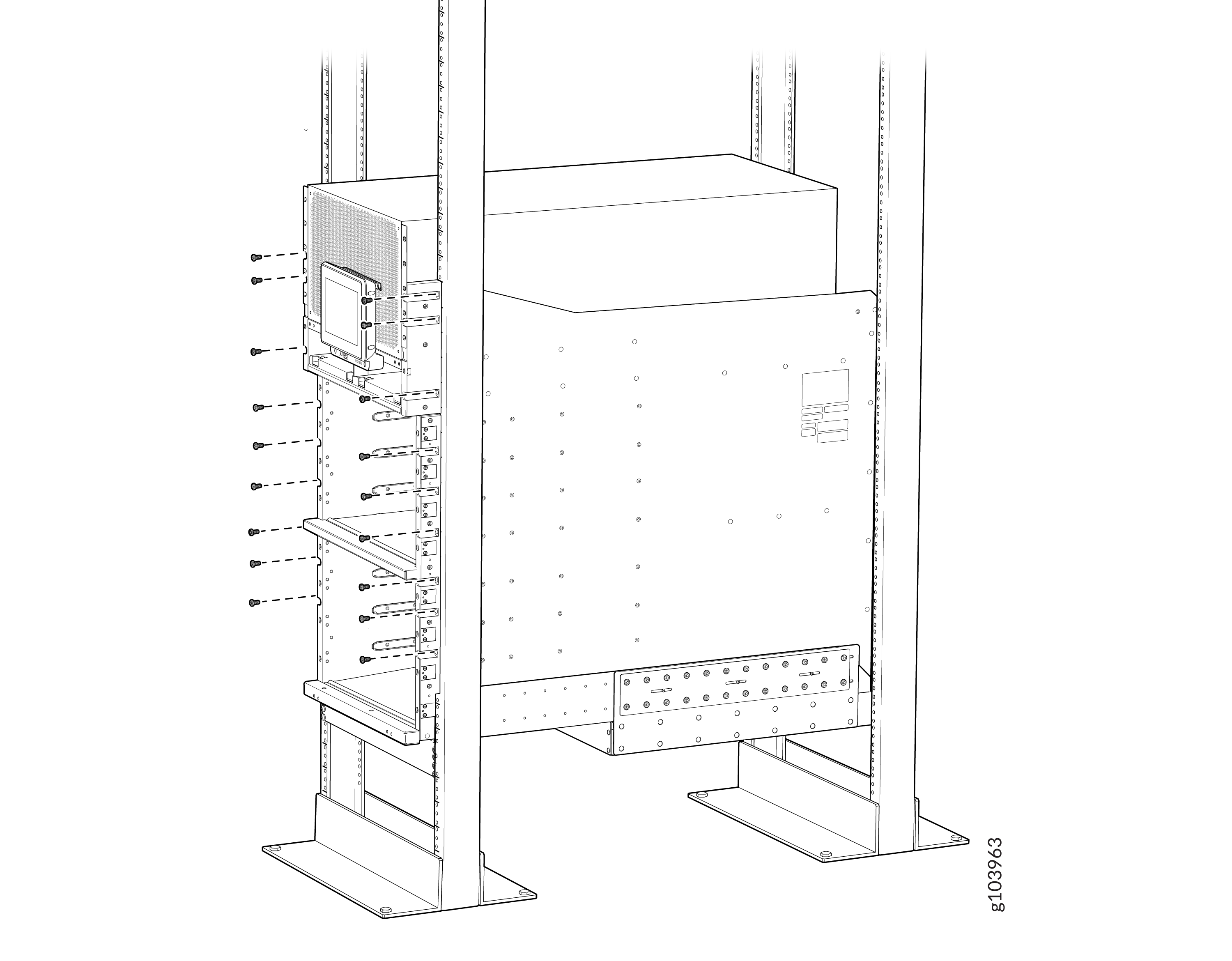
-
Attach the two chassis flanges to the rack posts by using rack-mounting
screws appropriate for your rack and a screwdriver. You must use nine
rack-mounting screws for each chassis flange.
-
Attach the twPhillips M4x8mm pan head rear side brackets to the rack by
using rack-mounting screws appropriate for your rack and a screwdriver. You
must use eight rack-mounting screws for each mounting bracket. Depending on
the location of the rack posts in relation to the chassis, you can attach
the rear side brackets in two different orientations. Figure 6 shows the orientation of the
brackets when the chassis extends out of the rack posts. Figure 7 shows the orientation of the
brackets when the chassis is inside the rack posts.
Figure 6: Attach the Rear Side Brackets to the Rack When the Chassis Extends Out of the Rack Posts
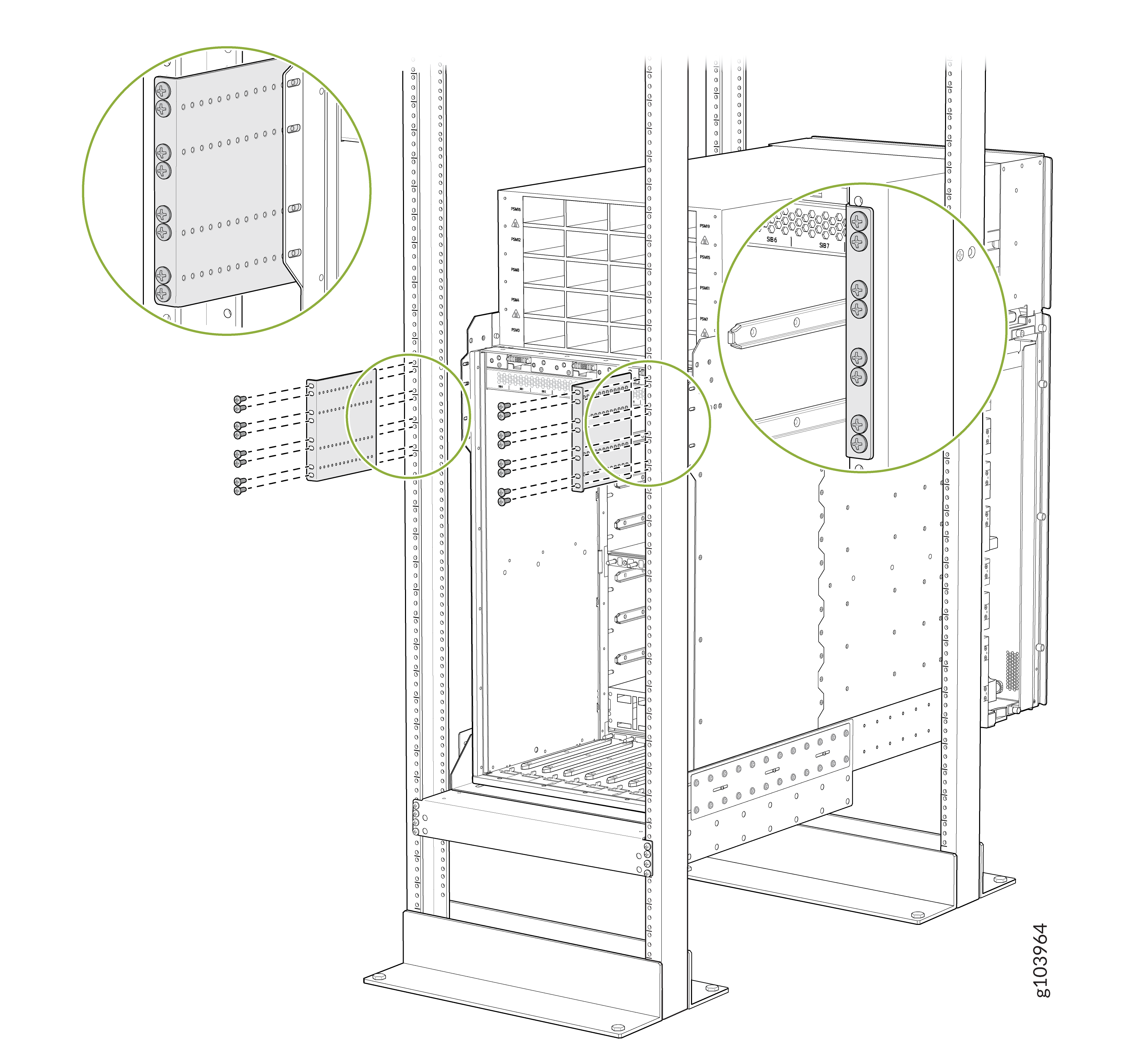 Figure 7: Attach the Rear Side Brackets to the Rack When the Chassis Is Inside the Rack Posts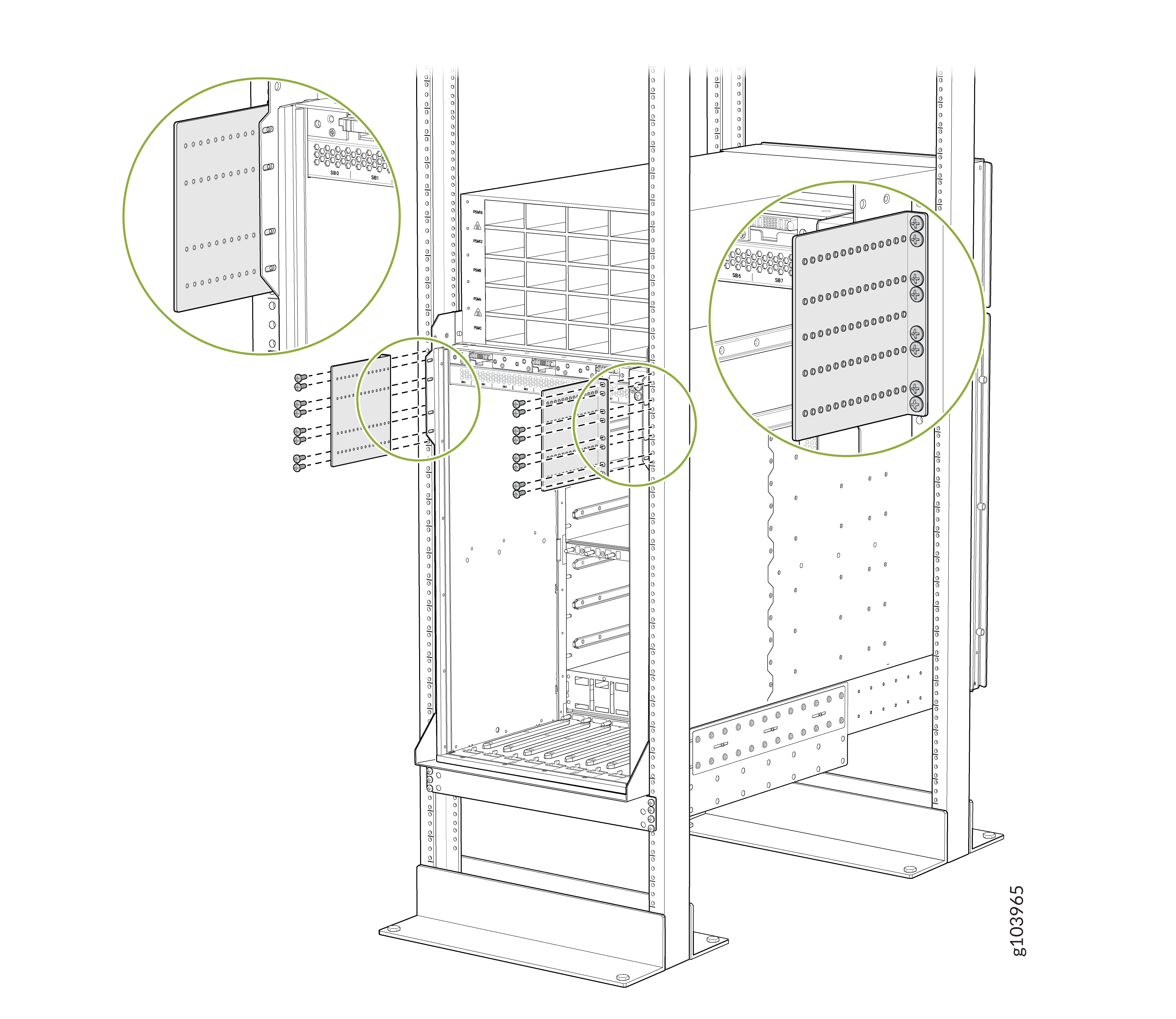
-
Attach the chassis to each rear side brackets by installing eight Phillips
M4x8mm pan head screws through each open flange hole and a screw slot on the
rack.
Tighten
the screws using a Phillips (+) screwdriver, number 2. Apply 18 lb⋅in (2
Nm) of torque to the screws. Depending on the location of
the rack posts in relation to the chassis, you can use the rear brackets in
two different orientations. Figure 8
shows the orientation of the brackets when the chassis extends out of the
rack posts. Figure 9 shows the
orientation of the brackets when the chassis is inside the rack posts.
Figure 8: Attach the Chassis to the Rear Side Brackets When the Chassis Extends Out of the Rack Posts
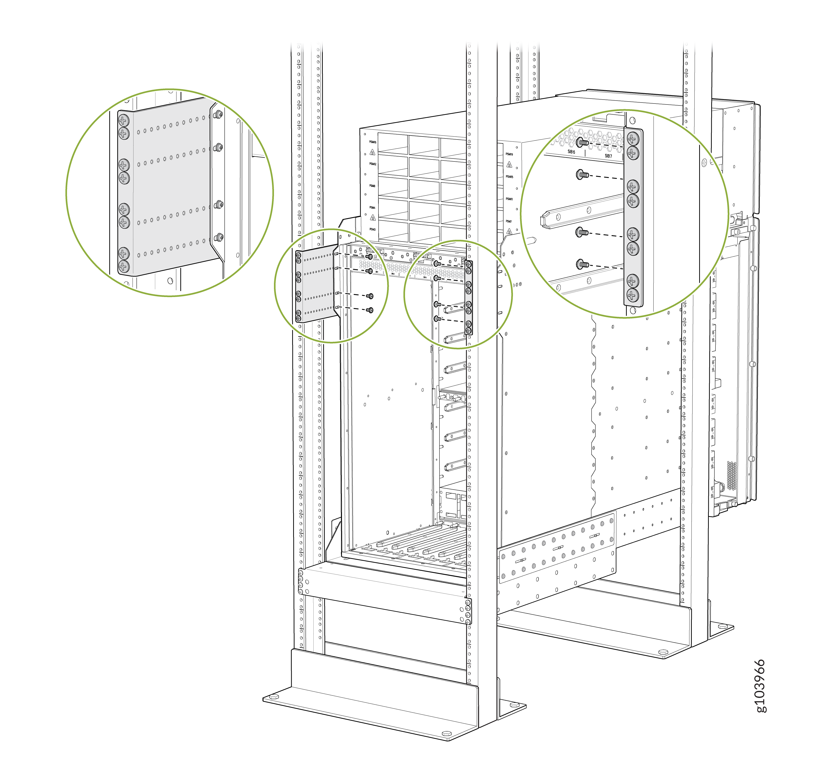 Figure 9: Attach the Chassis to the Rear Side Brackets When the Chassis Is Inside the Rack Posts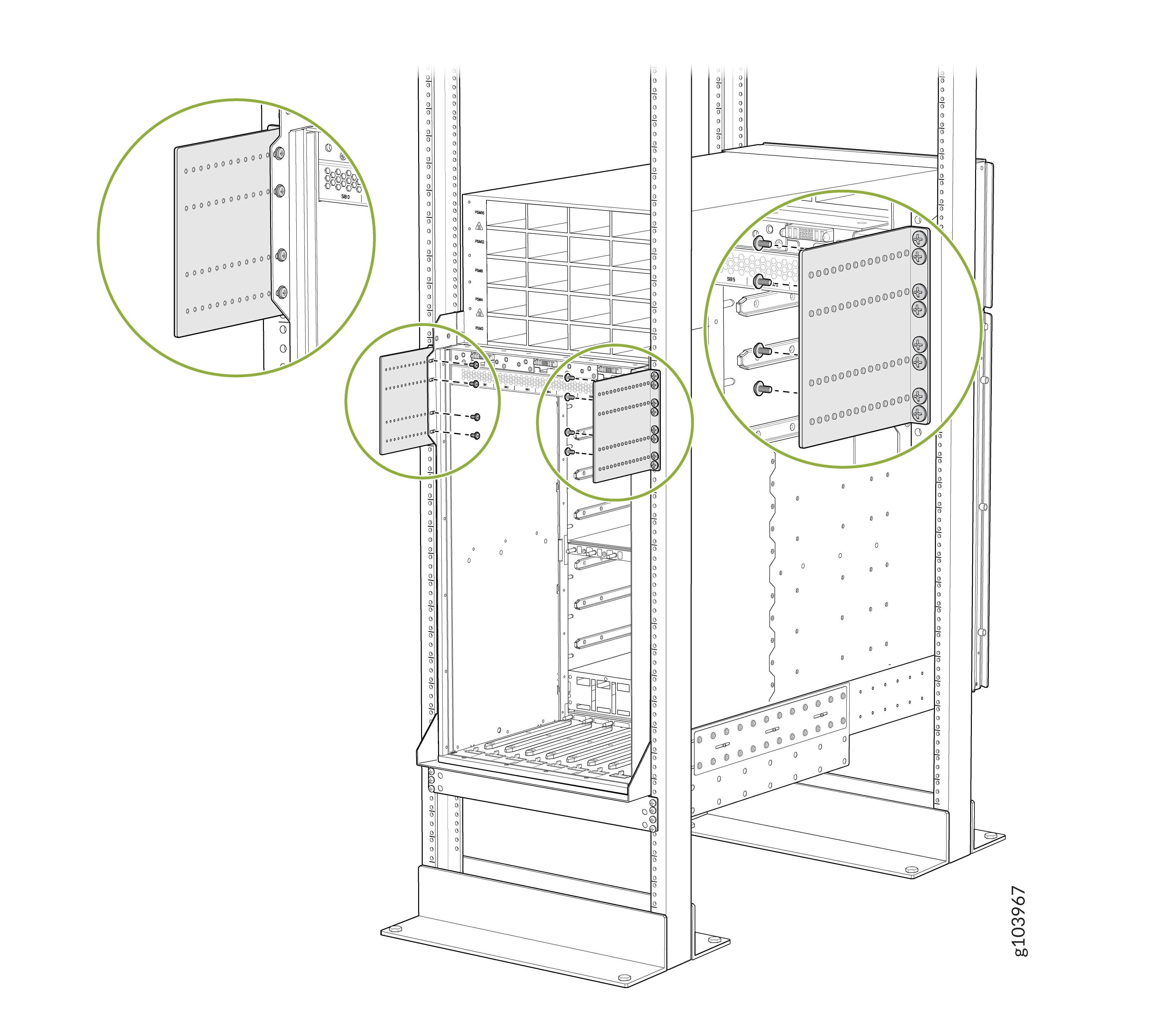
To install RCBs, FPCs, transceivers, PSMs, SIBs, or fan trays in the chassis, see:
Install the Bracket Kit
This topic guides you through the steps to install the bracket kit.
You must install the bracket kit before transporting the router installed in a rack or cabinet.
The fan trays do not work if the bracket kit is installed. Therefore, you must remove the bracket kit before powering on the router.
Before you install the bracket kit, review the following:
-
You must install the router in a rack or cabinet.
-
Ensure that you have a Phillips (+) screwdriver, number 2 available—not provided.
-
Use a Phillips (+) screwdriver, number 2 to loosen and tighten the screws.
To install the bracket kit:
-
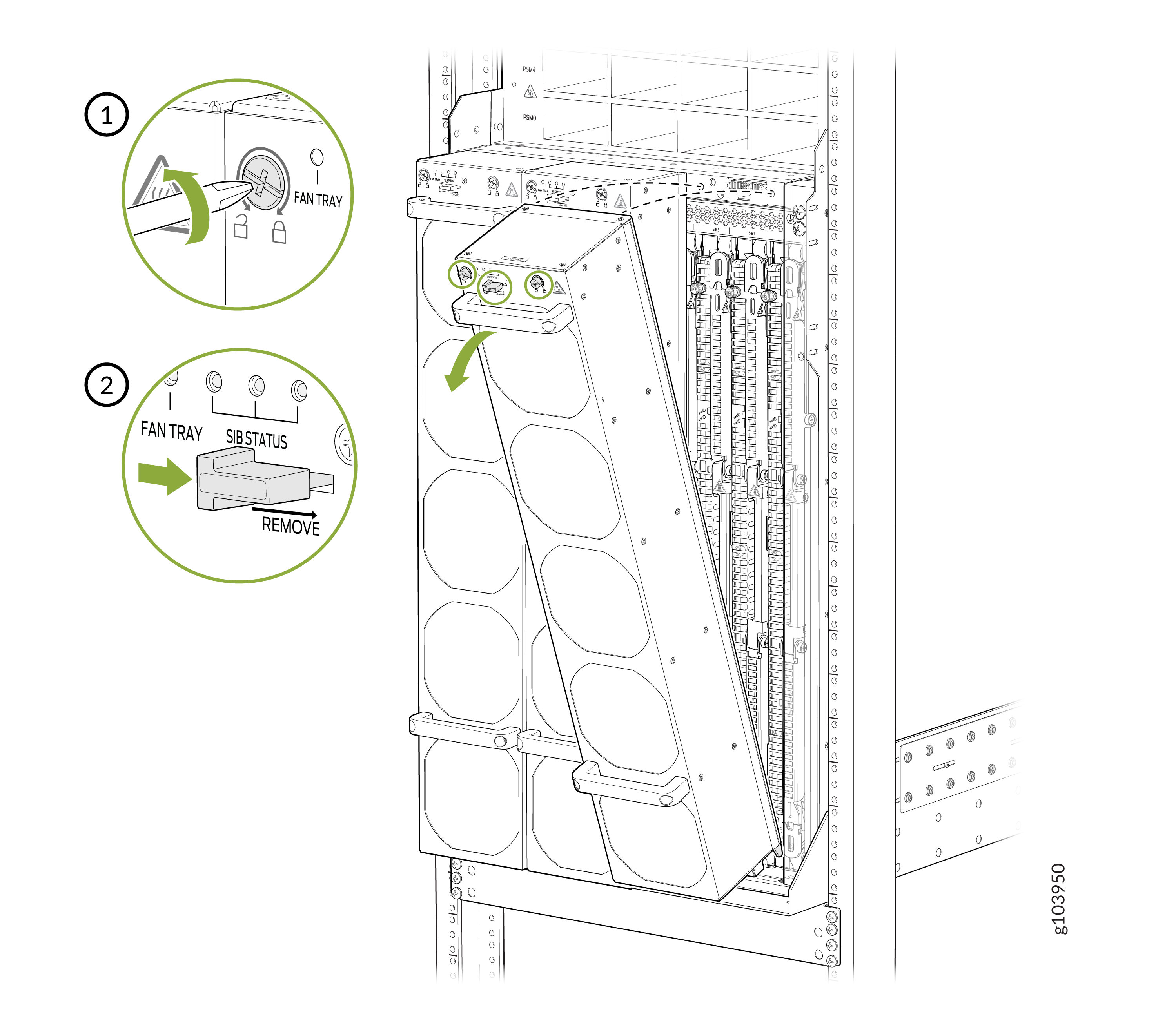
Remove the fan trays one by one.
-
Loosen the two screws on the fan tray.
-
Loosen the two screws on the fan tray.
-
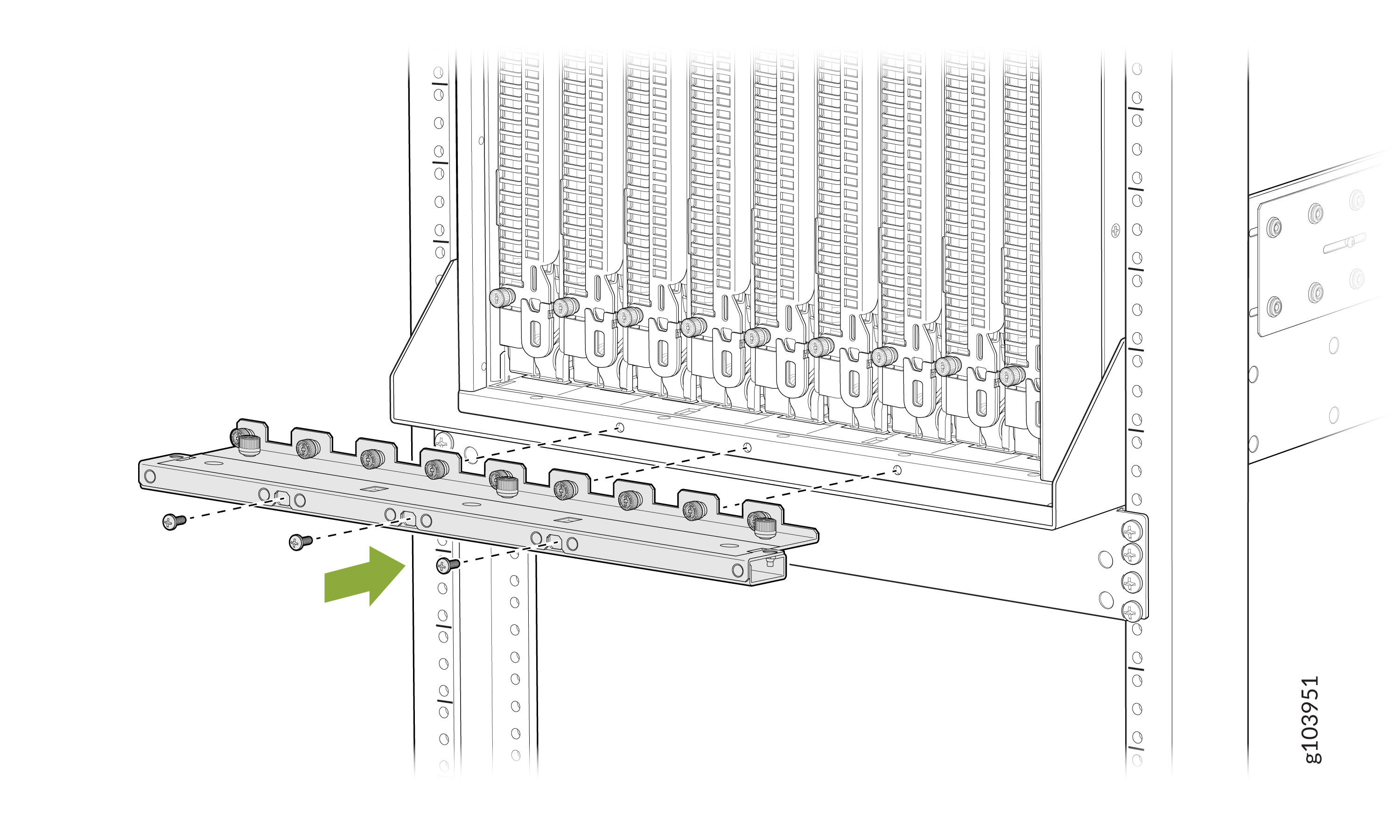
Install the lower SIB shipping bracket:
-
Position the lower SIB shipping bracket at the bottom of the
chassis.
-
Position the lower SIB shipping bracket at the bottom of the
chassis.
-
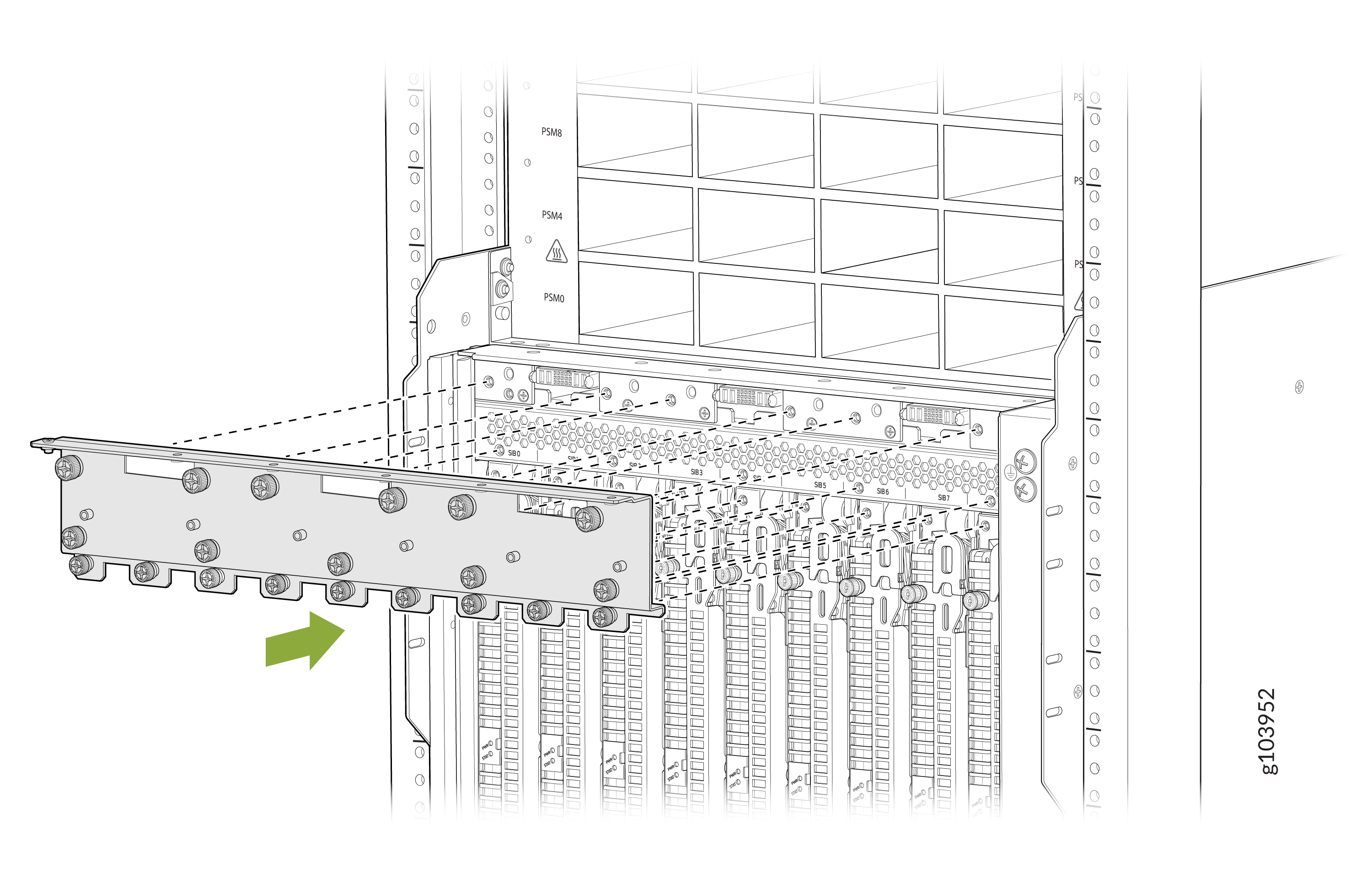
Install the upper SIB shipping bracket:
-
Position the upper SIB shipping bracket above the top of the
SIBs.
-
Position the upper SIB shipping bracket above the top of the
SIBs.
-
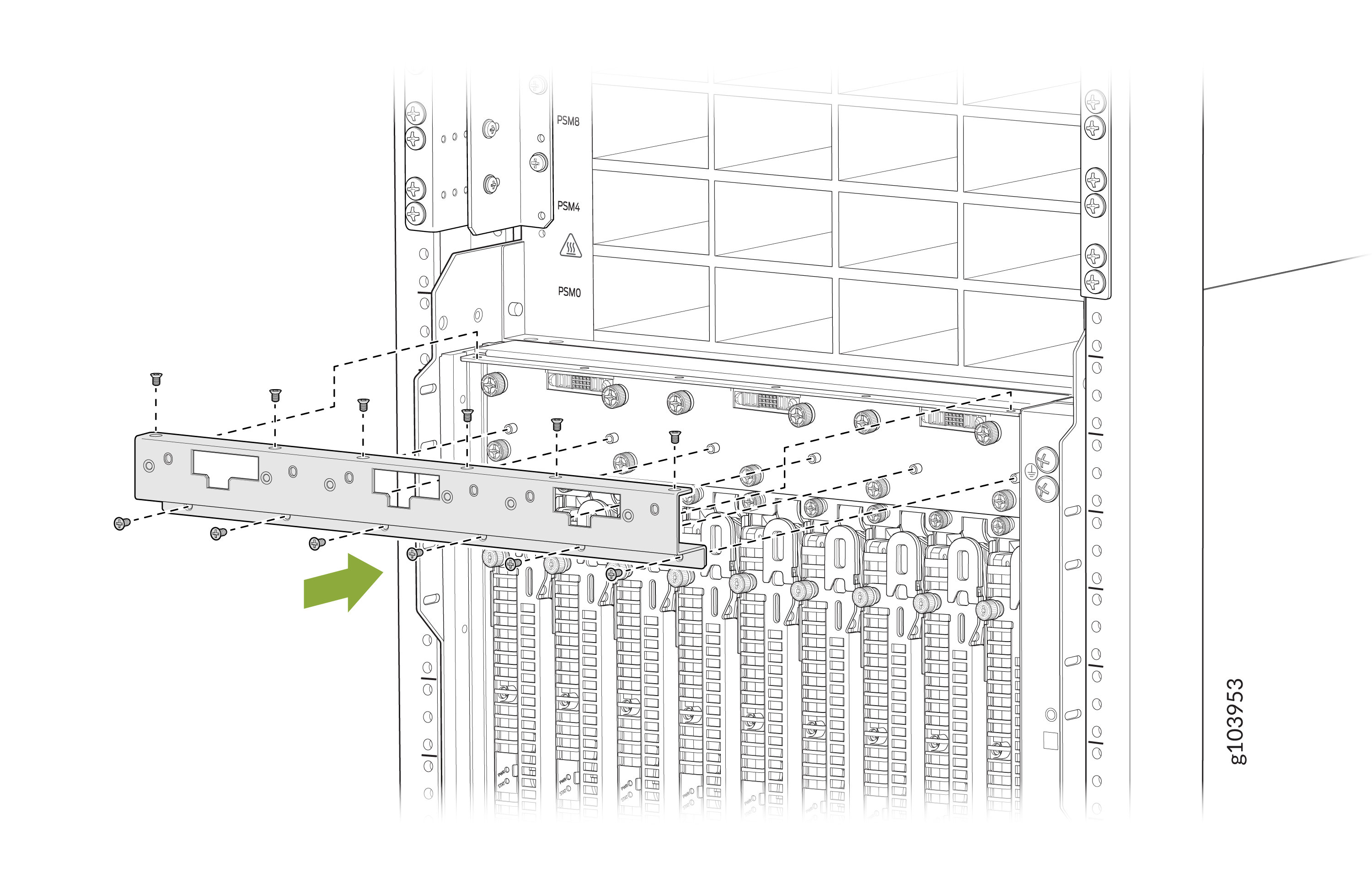
Install the fan tray mount shipping bracket.
-
Align the fan tray mount bracket with the upper SIB shipping
bracket. The top flange of the fan tray mount bracket must rest on
top of the top flange of the upper SIB shipping bracket.
-
Align the fan tray mount bracket with the upper SIB shipping
bracket. The top flange of the fan tray mount bracket must rest on
top of the top flange of the upper SIB shipping bracket.
-
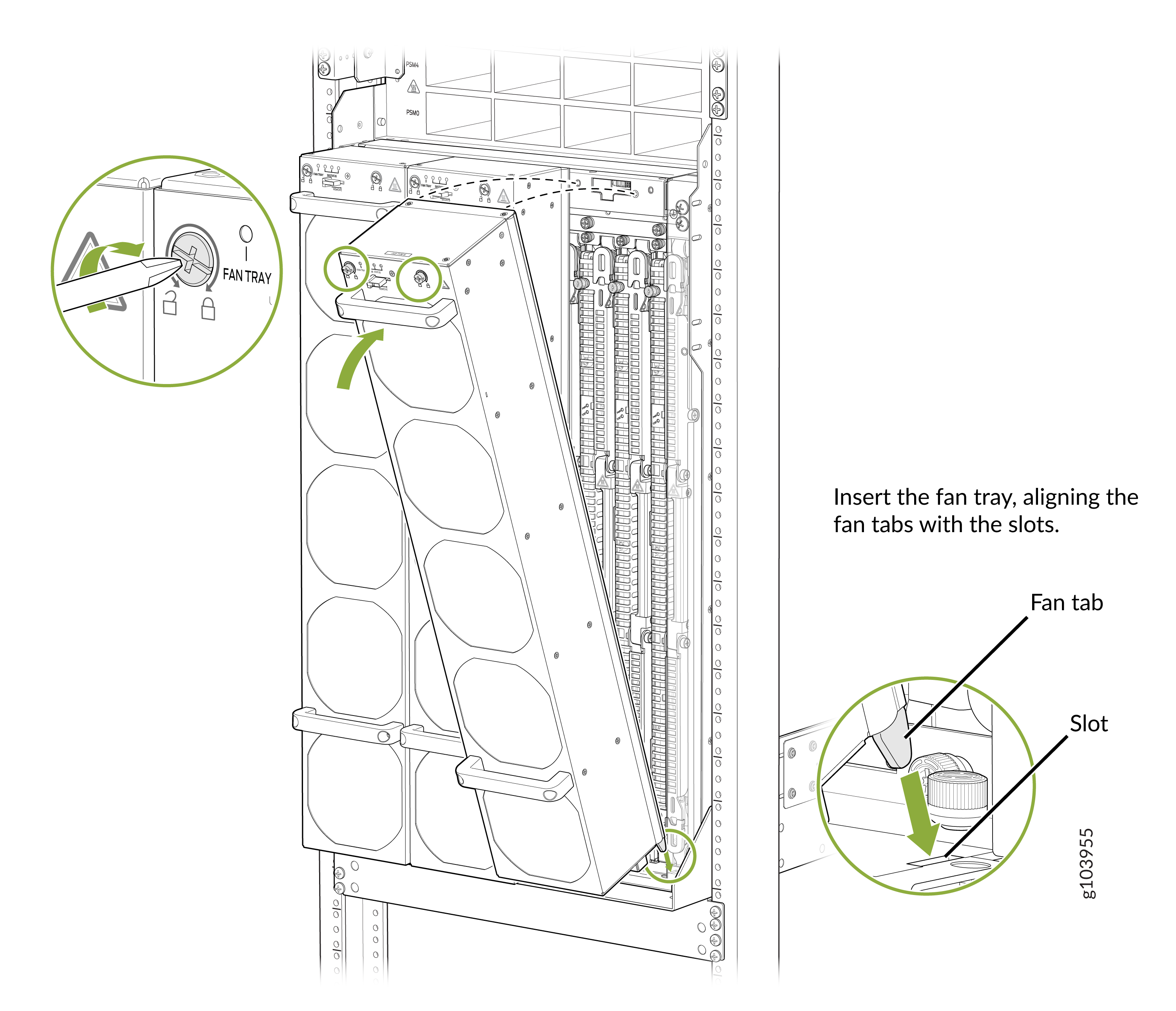
Install the fan tray one by one.
-
Align the bottom of the fan tray with the fan tray slot.
-
Align the bottom of the fan tray with the fan tray slot.
Remove the Bracket Kit
This topic guides you through the steps to remove the bracket kit.
The fan trays do not work if the bracket kit is installed. Therefore, you must remove the bracket kit before powering on the router.
Before you remove the bracket kit, review the following:
-
Ensure that you have a Phillips (+) screwdriver, number 2 available—not provided.
-
Use a Phillips (+) screwdriver, number 2 to loosen and tighten the screws.
To remove the bracket kit:
-
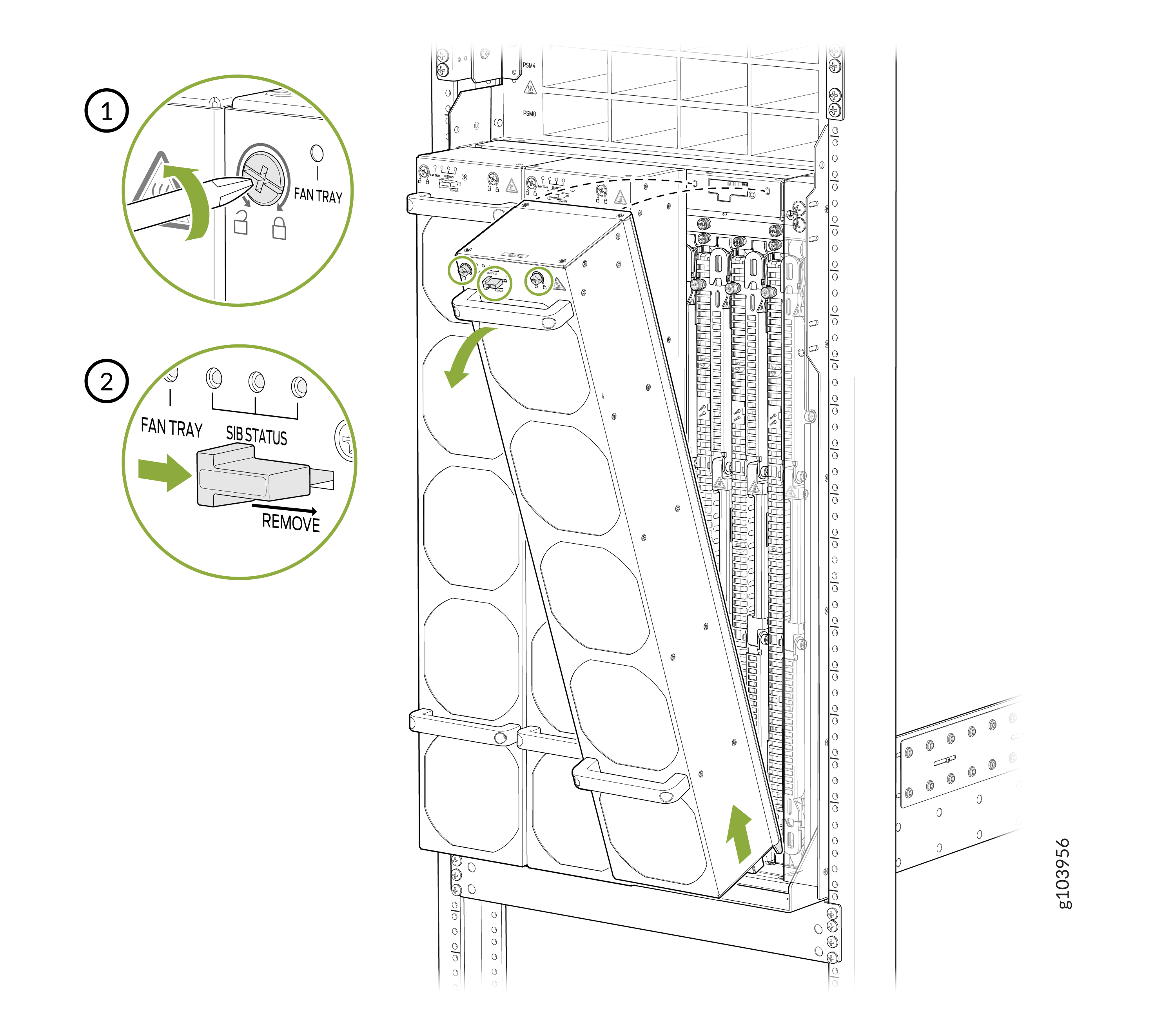
Remove the fan trays one by one.
-
Loosen the two screws on the fan tray.
-
Loosen the two screws on the fan tray.
-
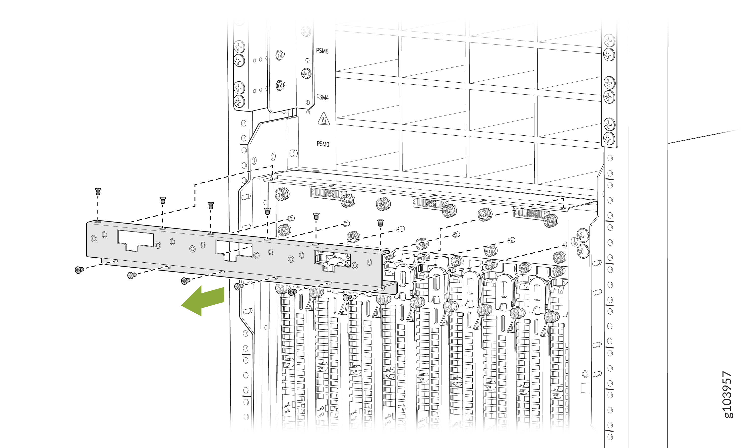
Remove the fan tray mount shipping bracket.
-
Remove the 12 flat head screws that secure the fan tray mount
shipping bracket.
-
Remove the 12 flat head screws that secure the fan tray mount
shipping bracket.
-
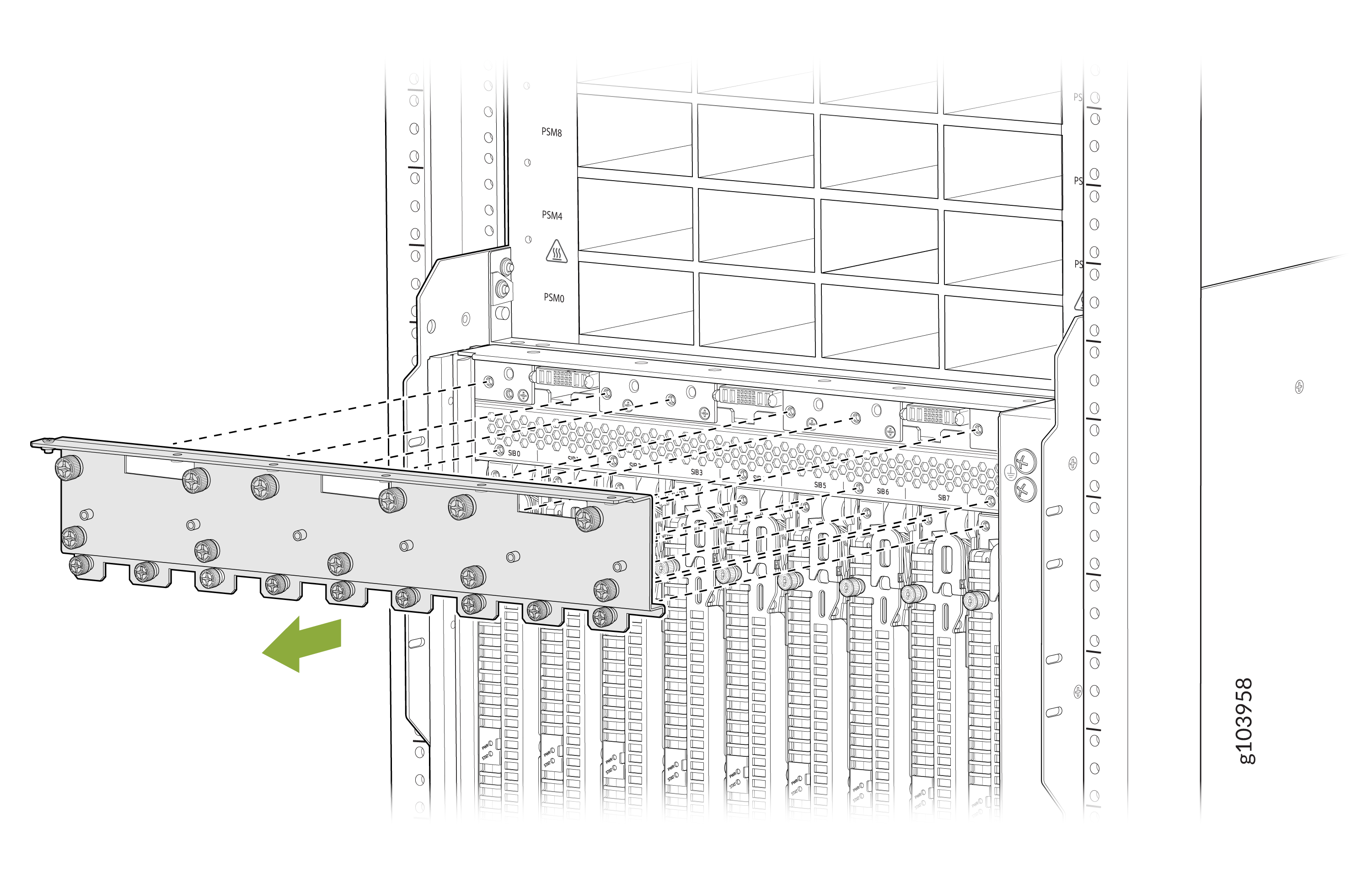
Remove the upper SIB shipping bracket:
-
Remove the 20 screws that secure the upper SIB shipping
bracket.
-
Remove the 20 screws that secure the upper SIB shipping
bracket.
-
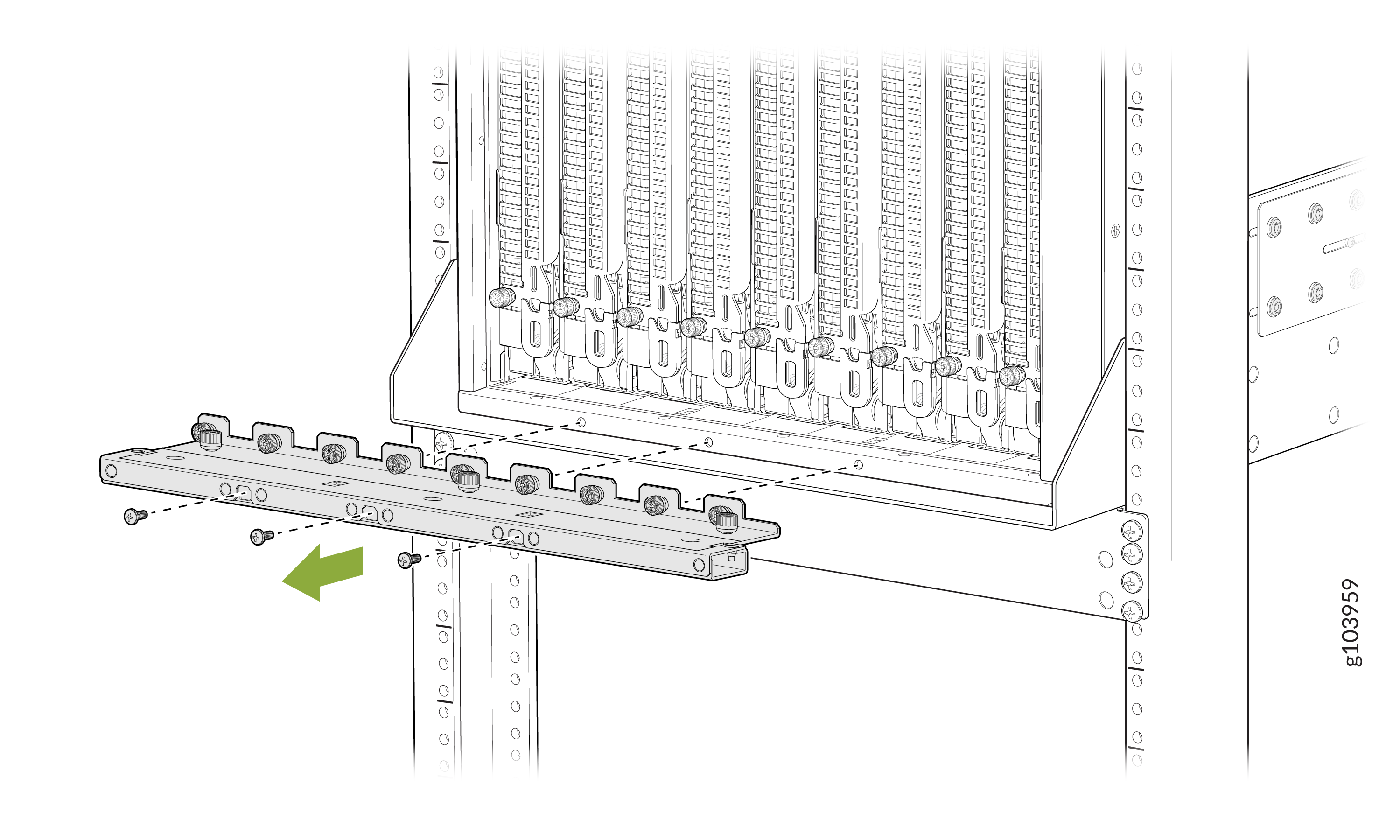
Remove the lower SIB shipping bracket:
-
Remove the 15 screws that secure the upper SIB shipping bracket.
Three screws are accessible through the openings on the rear face of
the bracket.
-
Remove the 15 screws that secure the upper SIB shipping bracket.
Three screws are accessible through the openings on the rear face of
the bracket.
-
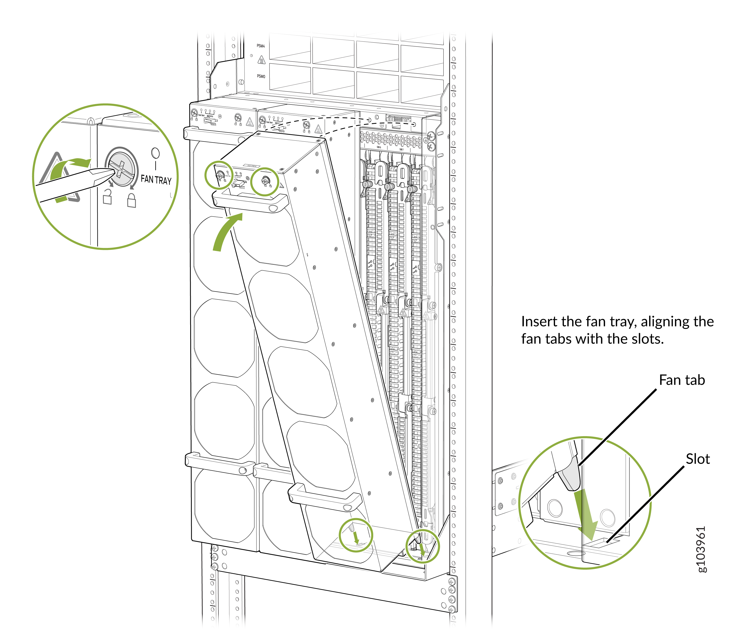
Install the fan tray one by one.
-
Align the bottom of the fan tray with the fan tray slot.
-
Align the bottom of the fan tray with the fan tray slot.
Install the Front Door
The front door protects fiber-optic cabling and provides additional protection from electromagnetic interference (EMI).
Before you install the PTX12008 in a rack, review the following:
-
Ensure that you understand how to prevent electrostatic discharge (ESD) damage. See Prevention of Electrostatic Discharge Damage.
-
Ensure that you have the following parts and tools available:
-
An ESD grounding strap—not provided
-
A Phillips (+) screwdriver, number 2—not provided
-
To install the front door on a PTX12008:
-
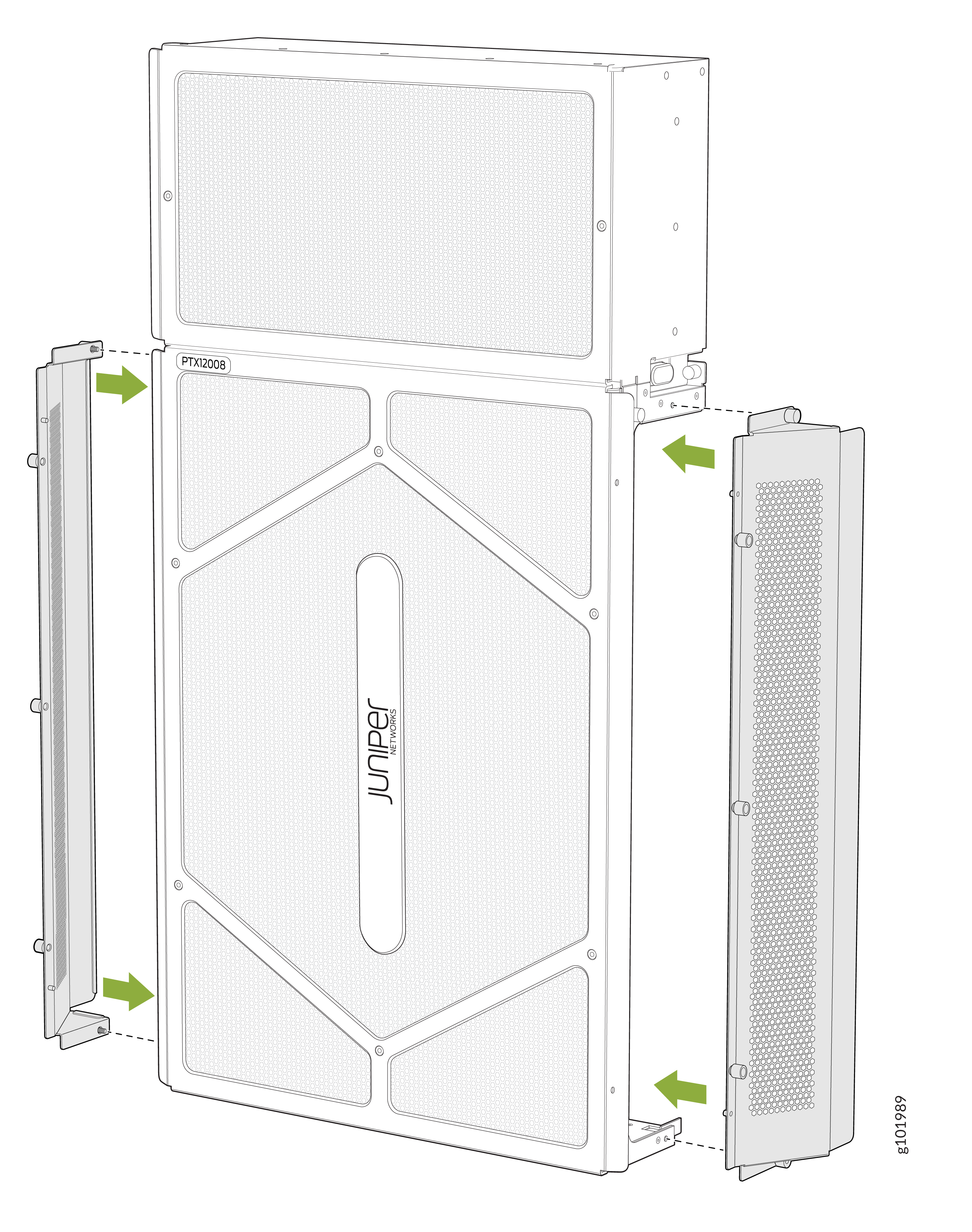
The front door comes in three pieces. Assemble the front door. Attach the
side panels
of the
front door to the front panel
of the
front door by inserting the five thumb screws located on
each side panel into the front panel. Tighten the screws.
-
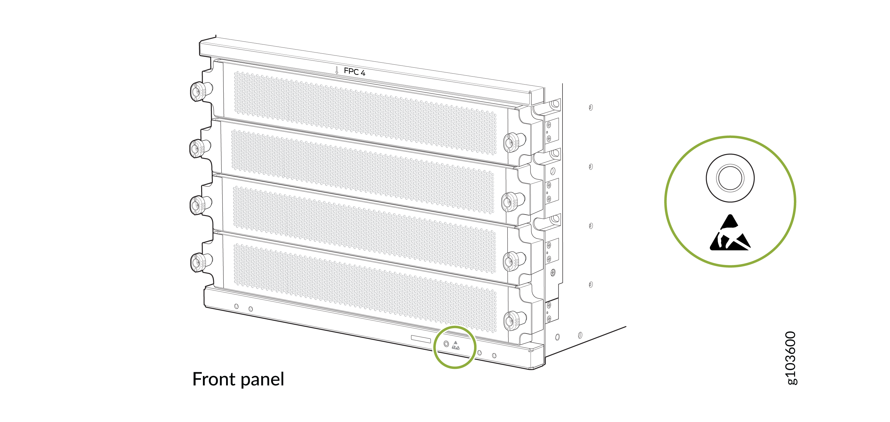
Wrap and fasten one end of the ESD grounding strap around your bare wrist
and connect the other end of the strap to the ESD point on the front panel
of the chassis.
Figure 10: ESD Point on the Front Panel of the Chassis
-
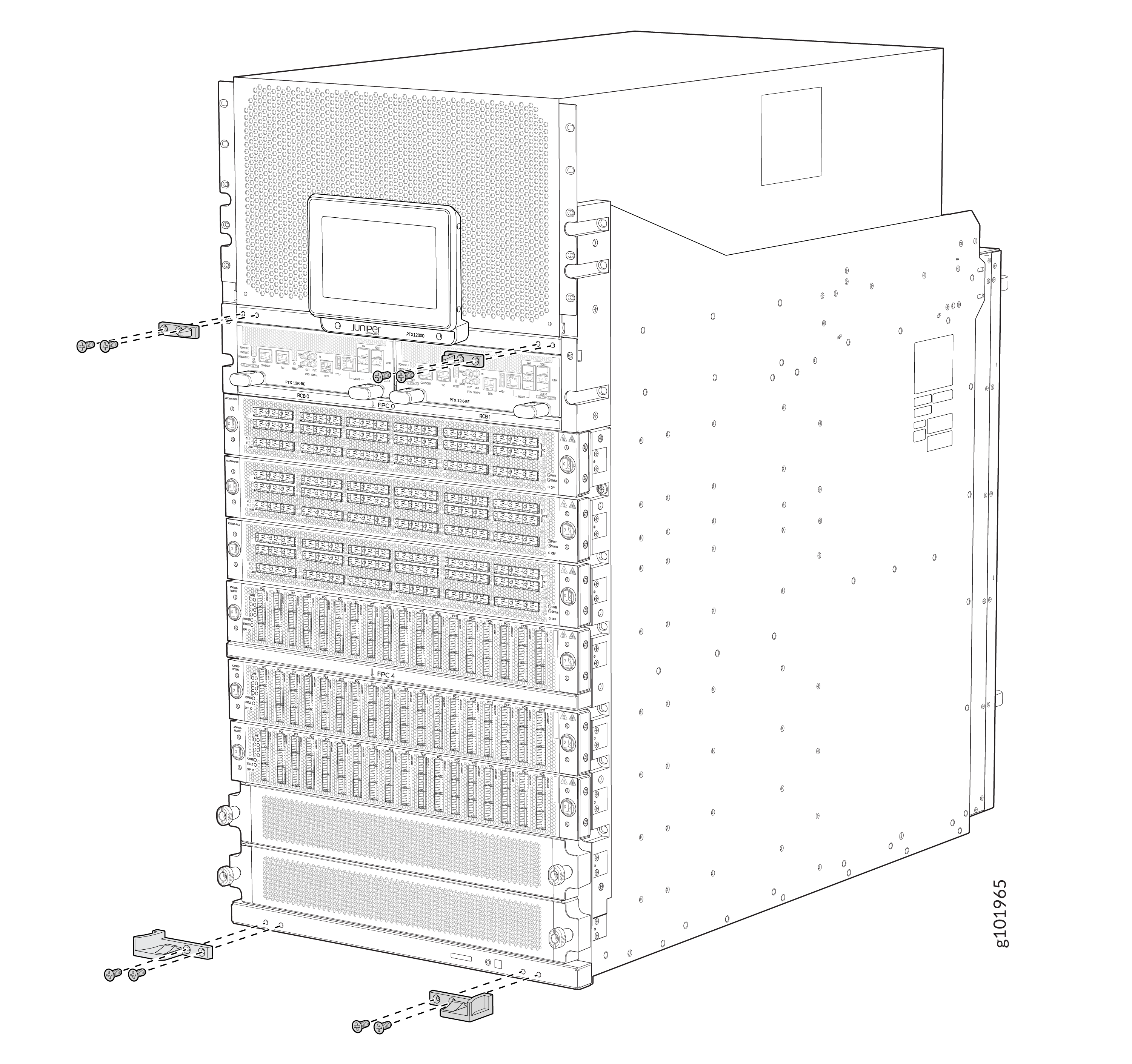
Attach the right and left base brackets to the lower front of the chassis
by using four of the 8-32x 0.5" flat-head screws supplied. Tighten the
screws using a Phillips (+) screwdriver, number
2. Apply
15 lb⋅in (1.7 Nm) of torque.
Note:
The base brackets are larger than the latch brackets. The right and left base bracket cannot be interchanged.
Figure 11: Hardware for Mounting Front Door 1—
1—Latch brackets
3—Left base bracket
2—Right base bracket
-
Attach the two latch brackets to the chassis by using four of the 8-32x0.5"
flat-head screws supplied. Screw holes for each latch bracket are located
between the power shelf and the Routing and Control Boards (RCBs). Tighten
the screws using a Phillips (+) screwdriver, number
2. Apply
15 lb⋅in (1.7 Nm) of torque.
-
Tighten the two captive screws by using your fingers or a Phillips (+)
screwdriver, number 2.
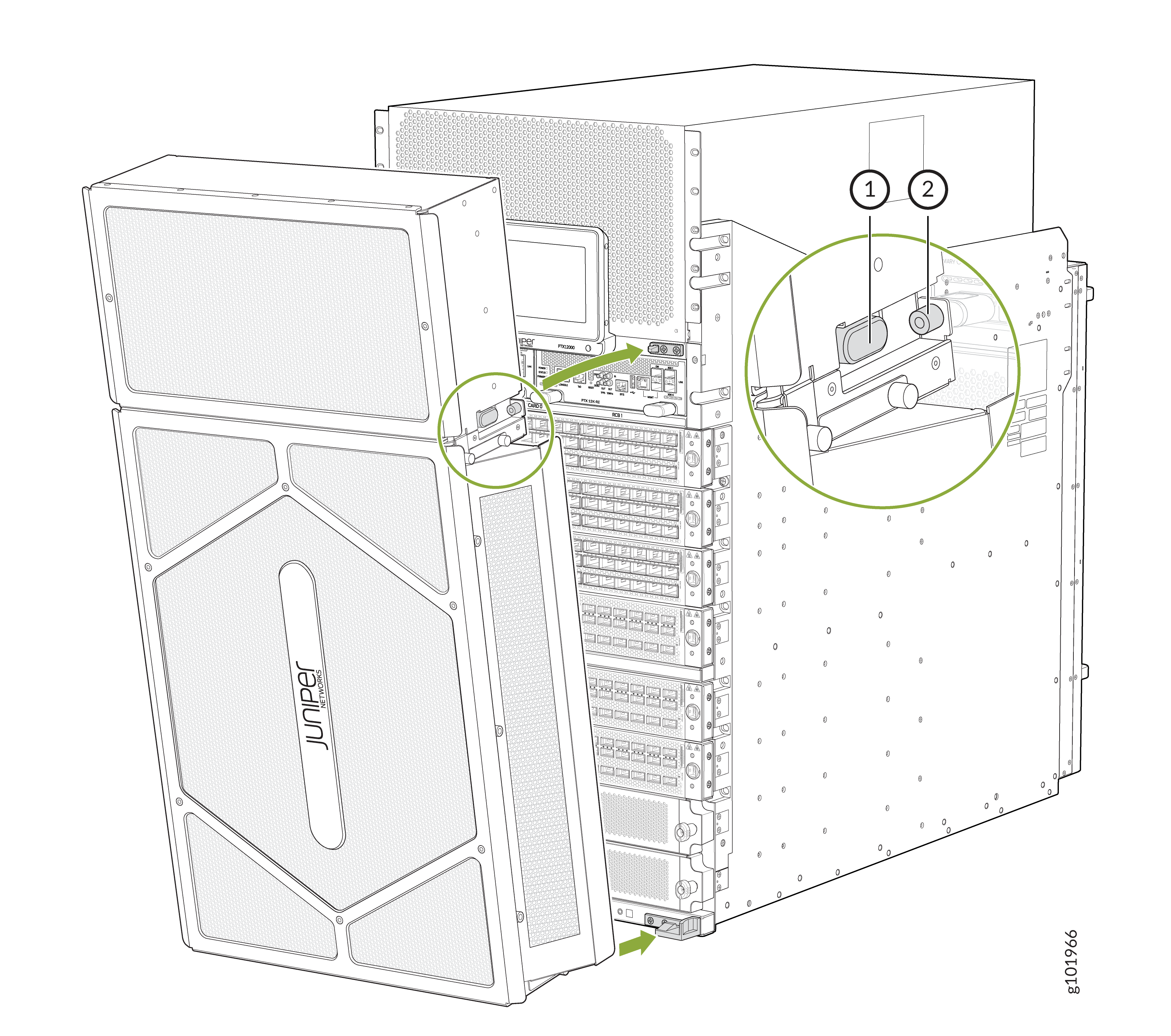 1—
1—Release button
2—Captive screw