Replace the Switch Interface Board on the PTX12008

Maintaining the PTX12008 includes removing and installing the Switch Interface Boards.

A PTX12008 supports up to nine Switch Interface Boards (SIBs) that are installed in the middle of the chassis, between the Flexible PIC Concentrators and the fan trays.

The SIBs are hot-removable and hot-insertable field-replaceable units (FRUs). You can remove and replace the SIBs without powering off the PTX12008 or disrupting the router functions.

Remove a SIB from the PTX12008

You must remove the appropriate fan tray before you remove a SIB. See Remove a Fan Tray from the PTX12008.

Ensure that you have taken the necessary precautions to prevent electrostatic discharge (ESD) damage. See Prevention of Electrostatic Discharge Damage.

Ensure that you have the following parts and tools available:

  • An ESD grounding strap—not provided

  • An antistatic bag or an antistatic mat—not provided

  • A replacement SIB or a cover for the SIB slot

  • A pair of heat resistant gloves—not provided

  • A Phillips (+) screwdriver, number 2—not provided
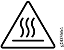
Warning:

Warning symbol indicating hot surface with wavy heat lines inside a triangle.Extreme burn danger—Do not handle a SIB running in the chassis without wearing heat-protective gloves.

To remove a SIB:

  1. Take the SIB offline using the request chassis sib slot slot number offline command.
    Note:

    If you suspect the SIB is faulty and want to ensure that packets do not flow through the SIB, power off the SIB instead of taking the SIB offline. To power off the SIB, use the set chassis sib power-off slot slot number command. Before you bring a new SIB in that slot online, you must delete the old configuration using the delete chassis sib power-off slot slot number command.

  2. Place an antistatic bag or an antistatic mat on a flat, stable surface.
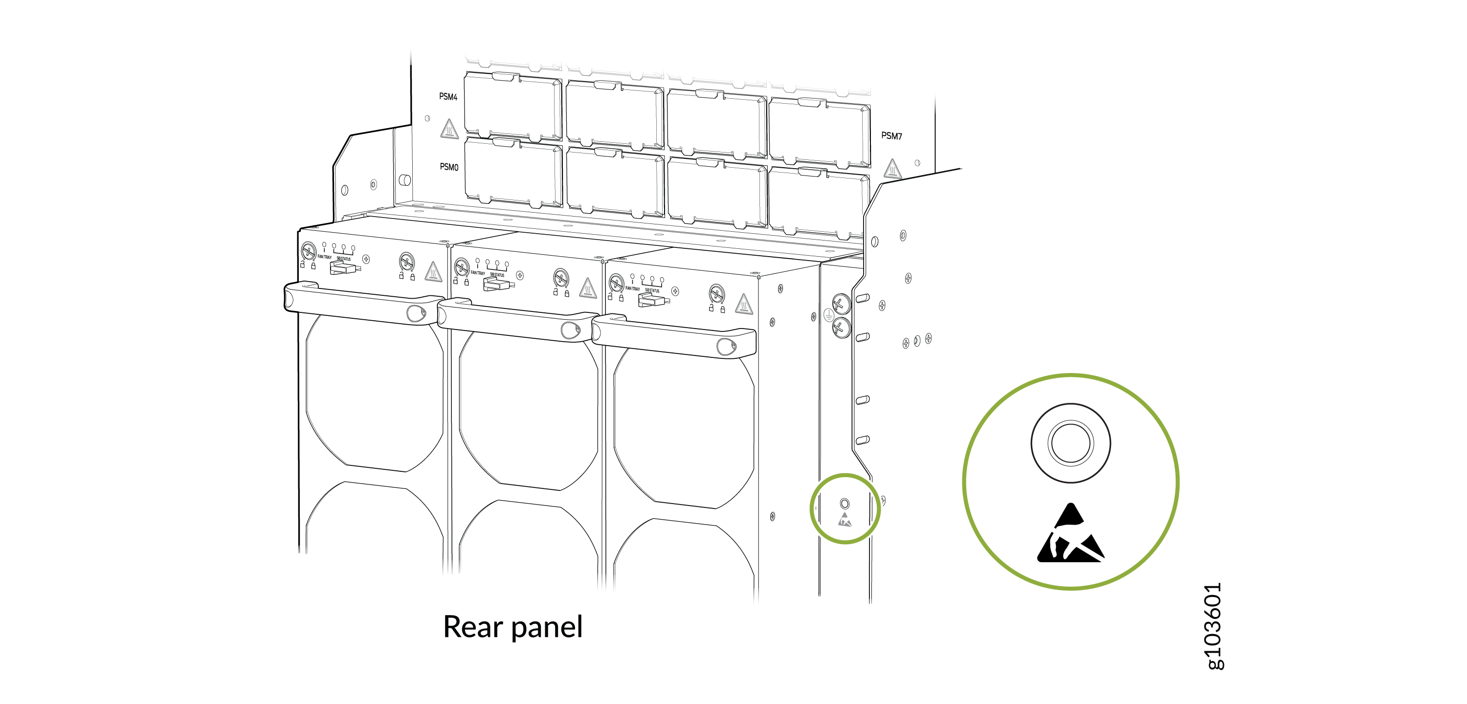
  3. Wrap and fasten one end of the ESD grounding strap around your bare wrist and connect the other end of the strap to the ESD point on the rear panel of the chassis.
    Figure 1: ESD Point on the Rear Panel of the Chassis Rear panel illustration of an electronic device showing slots, connectors, and a green-highlighted warning symbol indicating caution near a labeled area g103601.
  4. Remove the appropriate fan tray in front of the SIB slot (see Remove a Fan Tray from the PTX12008). The SIBs slots SIB0 through SIB2 are behind the fan tray on the left, SIB3 through SIB5 are behind the fan tray in the middle, and SIB6 through SIB8 are behind the fan tray on the right.
    CAUTION:

    Warning symbol indicating hot surface with wavy heat lines inside a triangle.The SIB surfaces are hot.

  5. Wear the heat-protective gloves.
  6. Using a Phillips (+) screwdriver, number 2, loosen the captive screws at the top and bottom of the SIB.
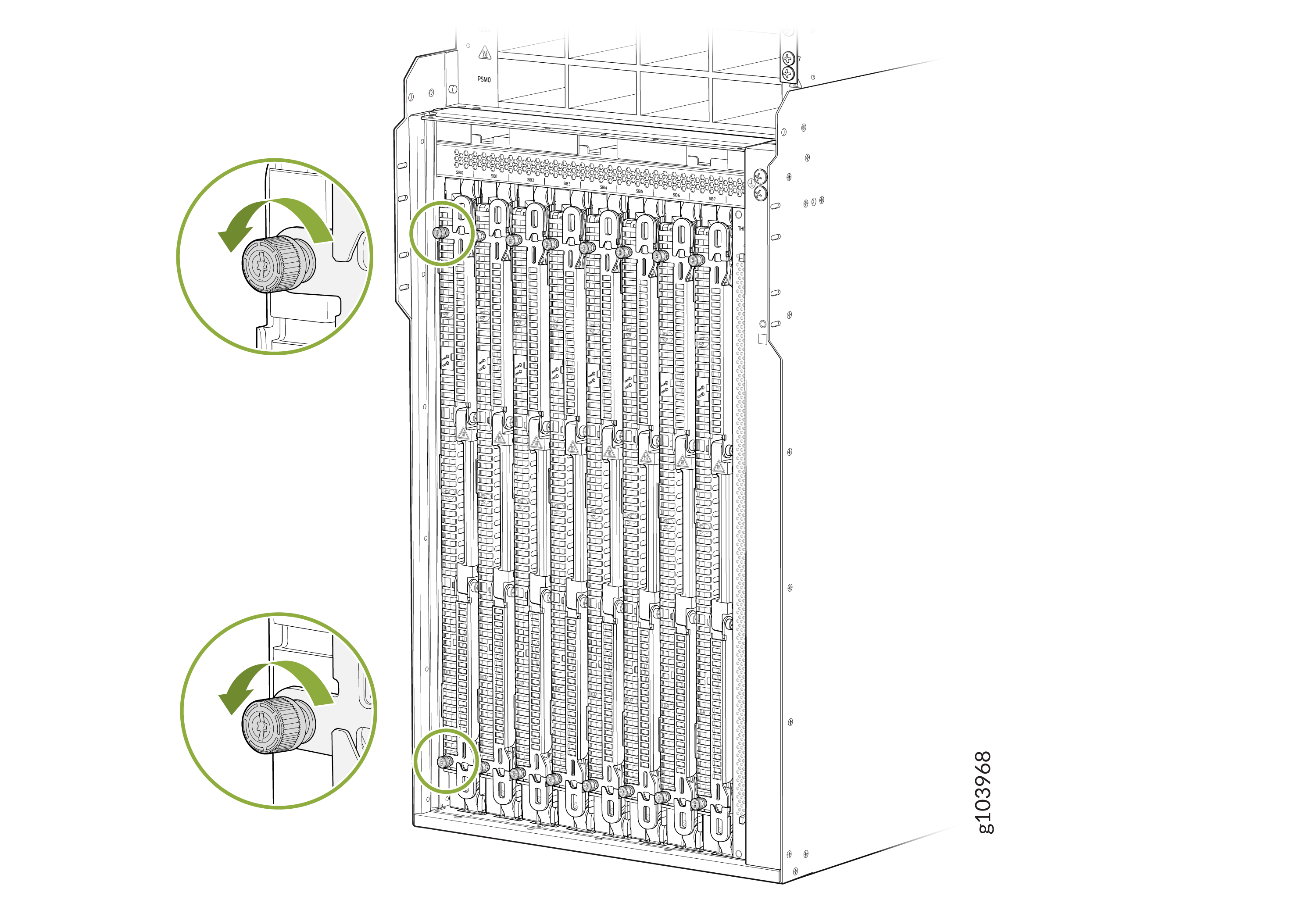
    Technical diagram of a server chassis with slots for components, highlighted green circles and arrows show securing or releasing mechanisms.
  7. Grasp both ejector handles and pull them open simultaneously till the SIB slides about a quarter of the way out of the slot.
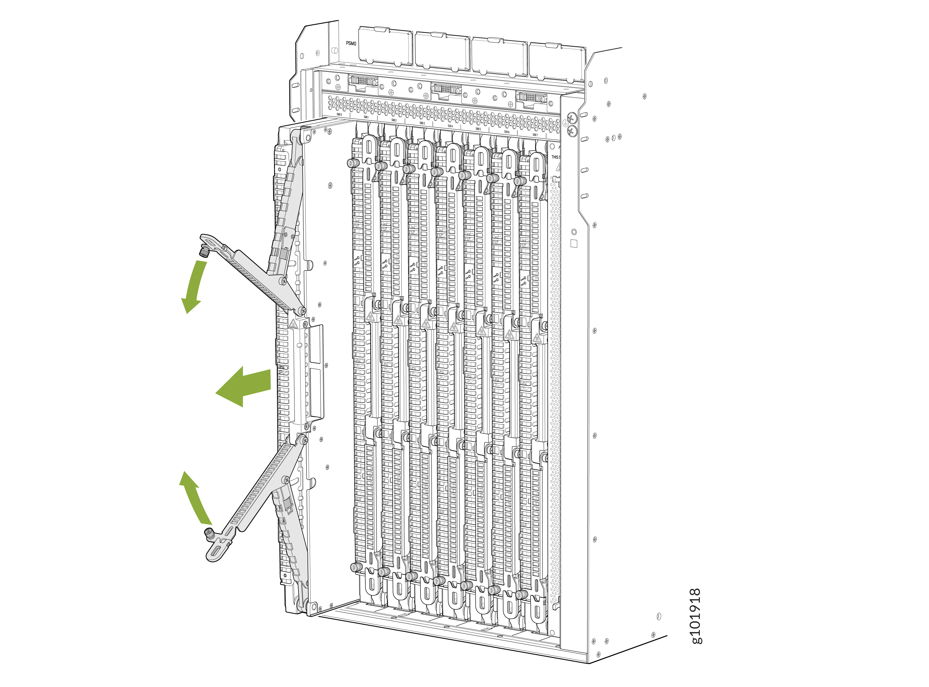
    Technical diagram of a server chassis showing vertical slots for server blades and two arms with green arrows indicating adjustment.
  8. Close the ejector handles.
  9. Grasp the top and bottom edges of the SIB and slide the SIB out of the slot.
  10. Place the SIB on the antistatic mat with the printed circuit board (PCB) facing upward. Be careful not to bump or handle the SIB by the connectors. If you do not have an antistatic mat, have another person help you slide the antistatic bag over the SIB before placing it on a stable surface.
    CAUTION:

    Do not stack hardware components on top of one another after you remove them. Place each component on an antistatic mat or in an antistatic bag kept on a stable, flat surface.

  11. If you are not replacing a SIB immediately, install a cover over the slot. To install the cover, place the cover in the slot and press it until it is fully seated. Do not operate the chassis without a SIB or a cover in place.

Install a SIB on the PTX12008

You can install up to nine SIBs behind the fan trays. You must remove the appropriate fan tray before you install a SIB. See Remove a Fan Tray from the PTX12008.

Ensure that you have taken the necessary precautions to prevent ESD damage. See Prevention of Electrostatic Discharge Damage.

Ensure that you have the following parts and tools available:

  • An antistatic bag or an antistatic mat—not provided

  • An ESD grounding strap—not provided

  • A Phillips (+) screwdriver, number 2—not provided

To install a SIB:

  1. Wrap and fasten one end of the ESD grounding strap around your bare wrist and connect the other end of the strap to the ESD point on the rear panel of the chassis.
    Figure 2: ESD Point on the Rear Panel of the Chassis Rear panel illustration of an electronic device showing slots, connectors, and a green-highlighted warning symbol indicating caution near a labeled area g103601.
  2. Remove the appropriate fan tray in front of the SIB slot (see Remove a Fan Tray from the PTX12008).
  3. If the SIB slot is covered, remove the cover on the SIB slot. Push the top latch down and the bottom latch up at the same time, and then pull the cover straight out. If you are replacing a SIB, remove the SIB you would like to replace (see Remove a SIB from the PTX12008).
    Figure 3: Remove the SIB Slot Cover Server chassis with green arrows and circles indicating alignment points, locking mechanisms, and orientation indicators, labeled THIS SIDE UP with a warning symbol.
  4. Grasp the top and bottom edges of the SIB and lift the SIB. Do not hold the SIB by the connector edge. The connectors are fragile and the SIB will not align and seat properly in the chassis if the connector is damaged.
  5. Hold the SIB vertically and slide the SIB about a quarter of the way into the open slot.
  6. Grasp both ejector handles and pull them open simultaneously.
  7. Slide the SIB into the slot until the ejector handles engage and start to close.

    If you are installing multiple SIBs, such as during a hardware upgrade, install the SIBs from the lowest slot number SIB0 to the highest SIB8. Do not skip slots.

  8. Grasp the ejector handles and fold them outward until they are fully closed.
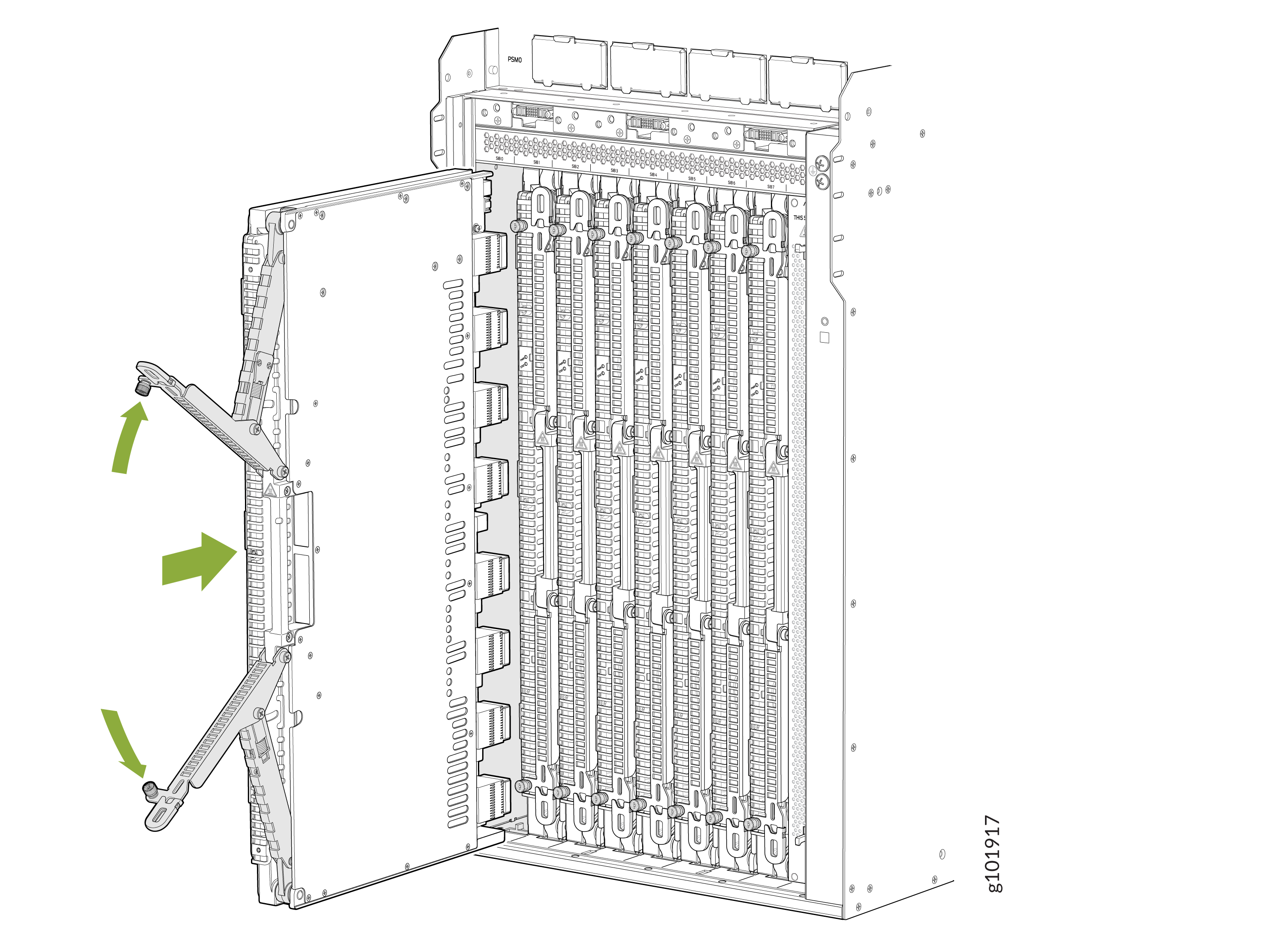
    Technical illustration of a server chassis with front panel open, showing vertically aligned slots for modular components and green arrows indicating panel movement.
  9. Using a Phillips (+) screwdriver, number 2, tighten the captive screws on the ejector levers.
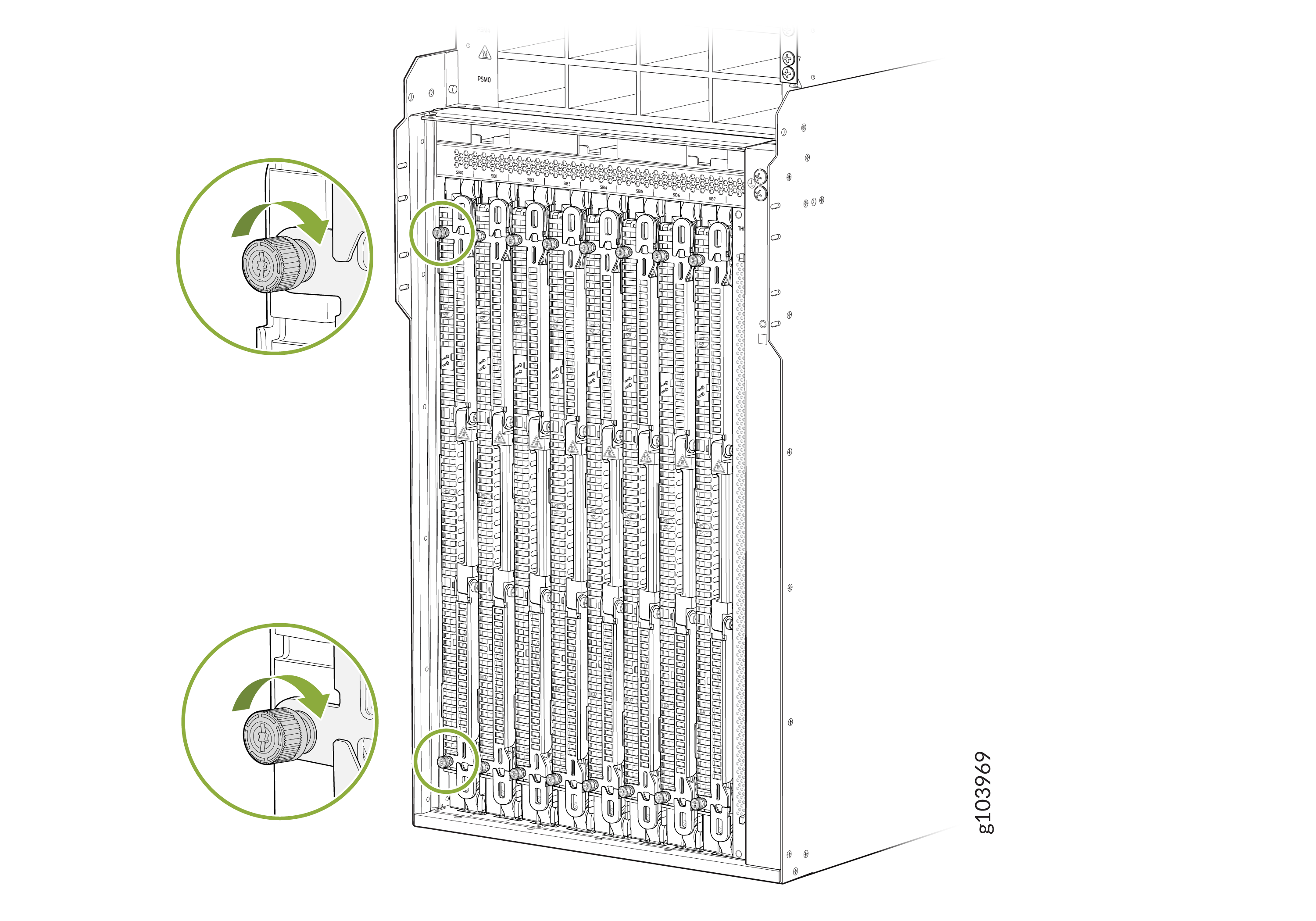
    Technical illustration of a server chassis with multiple slots for blades or modules, showing green circles and arrows pointing to knobs or screws for securing components.
  10. Bring the SIB online using the request chassis sib slot slot number online command.

    You can check the status of the SIB using the show chassis fabric sibs command and the show chassis fabric plane-location command.