Replace Flexible PIC Concentrators on the PTX12008

Maintaining the PTX12008 includes removing and installing the Flexible PIC Concentrators.

Flexible PIC Concentrators (FPCs) in the PTX12008 are hot-removable and hot-insertable field-replaceable units (FRUs). You can remove and replace the FPCs without powering off the PTX12008 or disrupting the router functions.

Remove an FPC from the PTX12008

You can remove an FPC from the PTX12008 by following the following steps.

Before you remove an FPC:

  • Ensure that you have taken the necessary precautions to prevent electrostatic discharge (ESD) damage. See Prevention of Electrostatic Discharge Damage.

  • If there are any optical cables or transceivers installed in the FPC, remove them. See Remove an OSFP or QSFP-DD Transceiver.

  • Ensure that you have the following parts and tools:

    • An ESD grounding strap—not provided

    • An antistatic bag or an antistatic mat—not provided

    • Two ejector tool handles—provided

    • A replacement FPC—not provided

    • A blank cover panel (if you are not replacing the FPC)—provided

    • A second person to assist with handling the FPC, or a lift—not provided

    • (If you need to remove the cable management system) A Phillips (+) screwdriver, number 2—not provided

To remove an FPC:

  1. Place the antistatic bag or antistatic mat on a flat, stable surface.
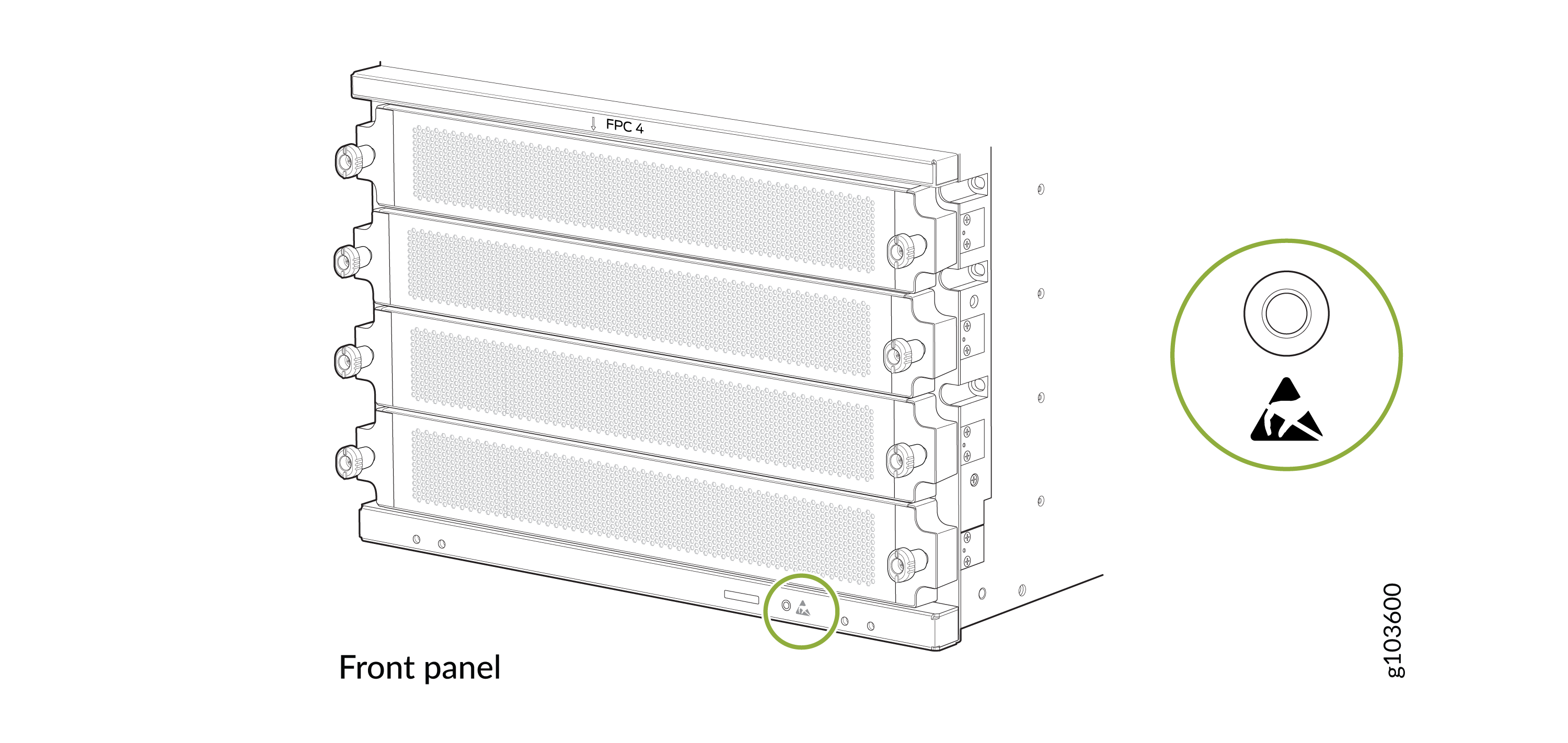
  2. Wrap and fasten one end of the ESD grounding strap around your bare wrist and connect the other end of the strap to the ESD point on the front panel of the chassis.
    Figure 1: ESD Point on the Front Panel of the Chassis Technical diagram of FPC 4 front panel with multiple slots and side connectors, featuring a highlighted warning triangle symbol and labeled g103600.
  3. If the front door is closed, open it.
    1. Loosen the two captive screws on the door by using your fingers or a Phillips (+) screwdriver, number 2.

    2. Press the release buttons on the sides of the door and gently pull the door away from the chassis.

  4. Label the cables connected to each port on the FPC so you can reconnect the cables to the correct ports.
  5. Take the FPC offline by using the request chassis fpc slot slot-number offline command.
  6. (Optional) If the cable management system is installed on the FPC, remove it.
    1. Push the clips that secure the tray to the extensions inward to open the clips.

    2. Gently pull the tray away from the extensions.

    3. Loosen the screws that attach the extensions to the FPC by using a Phillips (+) screwdriver, number 2.

    4. Gently pull the extensions out.

    5. Save the tray, extensions, and screws.

  7. Insert the ejector tool handles into the sockets for the ejector tool receptacles on either sides of the faceplate of the FPC. The ejector handles must be in vertical position. Press the button at the front of each tool and push the tools to attach them to the FPC.
  8. Rotate the ejector tool handles counterclockwise simultaneously until the FPC is fully unseated.
    CAUTION:
    The FPC weighs about 47 lb (21.3 kg). Have a second person to assist you to remove the FPC. If a second person is not available, use a lift to support the weight of the FPC.
  9. Hold the ejector tool handles and slide the FPC halfway out of the FPC slot.
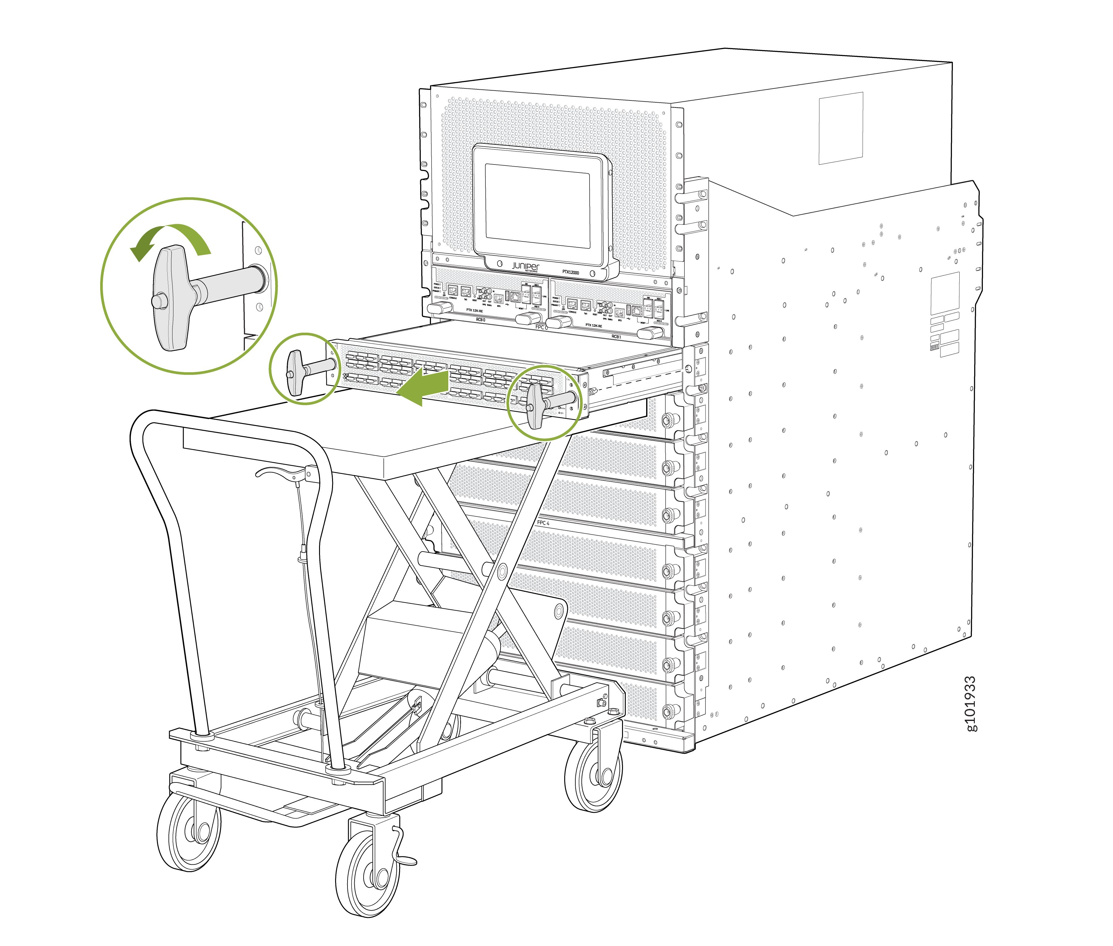
    Server being installed or removed from a rack using a sliding rail system and a lift cart, with green arrows highlighting actions.
    CAUTION:

    Do not stack FPCs on top of one another or on top of any other component. Place each FPC separately in the antistatic bag or on the antistatic mat placed on a flat, stable surface.

    CAUTION:

    Do not lift the FPC by holding the edge connectors or the faceplate. The edge connectors or the faceplate cannot support the weight of the FPC. Lifting the FPC by the edge connectors or faceplate might bend them, which would prevent the FPCs from being properly seated in the chassis.

  10. Grasp both sides of FPC at midpoint and remove the FPC from the chassis. Take care not to touch the connectors.
  11. Place the FPC in the antistatic bag or on the antistatic mat.
  12. If you are not installing an FPC in the FPC slot soon, install an FPC slot cover over the slot. This step protects the interior of the chassis from dust or other foreign substances and ensures that the airflow inside the chassis is not disrupted.

Install an FPC on the PTX12008

You can install an FPC on the PTX12008 by following the following steps.

Before you install an FPC:

  • Ensure that you have taken the necessary precautions to prevent ESD damage. See Prevention of Electrostatic Discharge Damage.

  • Ensure that the router has sufficient power to power the FPC while maintaining its n+1 power redundancy. To determine whether the router has enough power available for the FPC, use the Power Calculator.

  • Ensure that you have the following parts and tools available:

    • An ESD grounding strap—not provided

    • A Phillips (+) screwdriver, number 2—not provided

    • Two ejector tool handles—provided

    • A second person to assist with handling the FPC, or a lift—not provided

  • (Optional) Have the cable management system parts available:

    • A tray—provided

    • Two extensions—provided

    • Two screws—provided

To install an FPC:

  1. Wrap and fasten one end of the ESD grounding strap around your bare wrist and connect the other end of the strap to the ESD point on the front panel of the chassis.
    Figure 2: ESD Point on the Front Panel of the Chassis Technical diagram of FPC 4 front panel with multiple slots and side connectors, featuring a highlighted warning triangle symbol and labeled g103600.
  2. If the front door is closed, open it.
    1. Loosen the two captive screws on the door by using your fingers or a Phillips (+) screwdriver, number 2.

    2. Press the release buttons on the sides of the door and gently pull the door away from the chassis.

  3. If the FPC slot is covered, turn the screws on the cover counterclockwise and pull the slot cover gently out of the chassis. If there is an FPC installed in the slot, remove it.
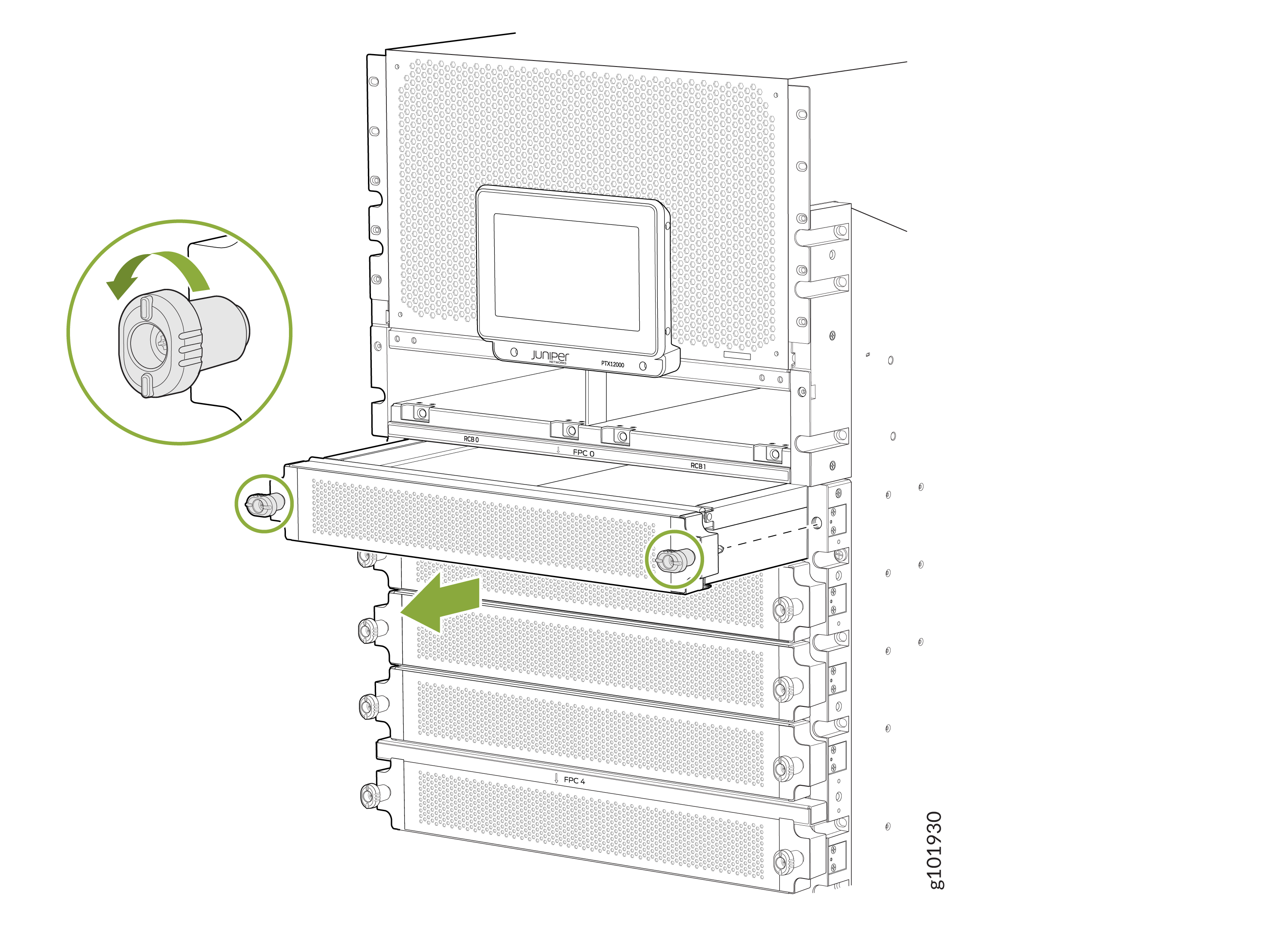
    Technical illustration of a network equipment rack showing installation or removal of a component with a green arrow, close-up of the locking mechanism with rotation arrows, and a display panel labeled Juniper.
  4. CAUTION:
    The FPC weighs about 47 lb (21.3 kg). Have a second person to assist you to remove the FPC. If a second person is not available, use a lift to support the weight of the FPC.
    Grasp both sides of FPC at midpoint and remove the FPC from the bag. Take care not to touch the connectors.
  5. Inspect the connector edge of the FPC and ensure that there is no physical damage. Installing a damaged FPC might damage the router.
  6. Insert the ejector tool handles into the sockets for the ejector tool receptacles on either sides of the faceplate of the FPC. The ejector handles must be in vertical position. Press the button at the front of each tool and push the tools to attach them to the FPC.
    CAUTION:
    The FPC weighs about 47 lb (21.3 kg). Have a second person to assist you to remove the FPC. If a second person is not available, use a lift to support the weight of the FPC.
  7. Grasp both sides of the FPC at midpoint and lift it. With the help of a second person or a lift, move the FPC close to the chassis and align the FPC with the FPC slots on the chassis.
  8. Gently slide the FPC into the slot until it stops. Ensure that the ejector handles are still in vertical position. Rotate the ejector tool handles clockwise simultaneously until the FPC is fully seated. You will hear an audible click sound and feel a tactile feedback vibration on each ejector handle when the FPC is fully seated. Do not rotate the ejector tool handles any further.
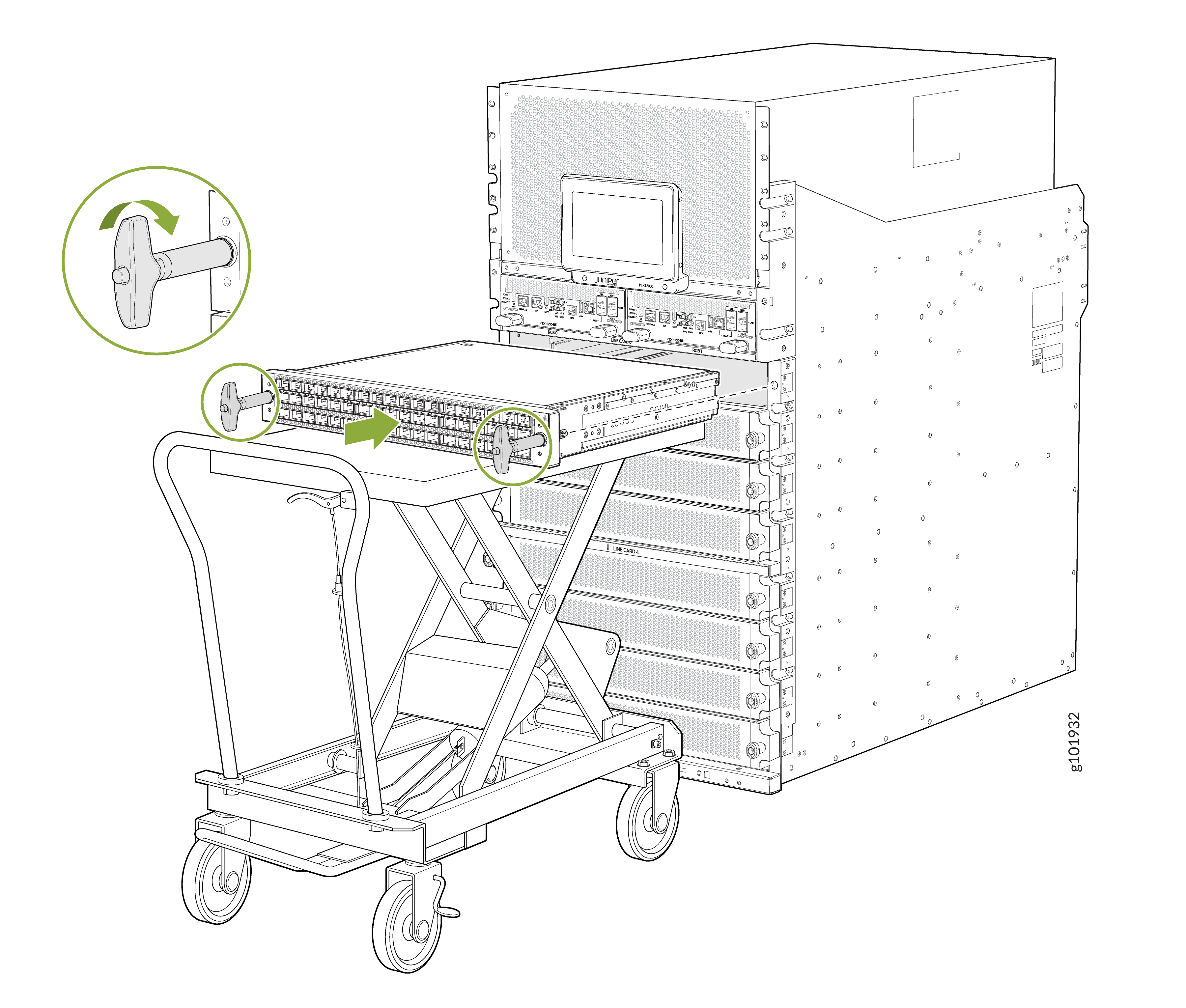
    Server equipment being installed or removed from a rack using a lift cart, showing a modular unit and handle mechanism for securing or releasing.
  9. Bring the FPC online by using the request-chassis-fpc slot slot-number online command.
  10. (Optional) Install the cable management system.
    1. Insert the extensions in the slots on FPC.

    2. Attach the extensions to the FPC by using the screws and a Phillips (+) screwdriver, number 2.

    3. Hang the tray on the extensions and push the clips outward to lock the clips.