Replace Power Supply Modules on the PTX12008
Maintaining the PTX12008 includes removing and installing the power supply modules.
The power supply modules (PSMs) in the PTX12008 are hot-removable and hot-insertable field-replaceable units (FRUs). You can remove and replace the PSMs without powering off the PTX12008 or disrupting the router functions.
Remove an AC/HVAC/HVDC PSM from the PTX12008
You can remove an AC/HVAC/HVDC PSM from the PTX12008 by following the following steps.
Before you remove an AC/HVAC/HVDC PSM:
-
Ensure that you understand how to prevent electrostatic discharge (ESD) damage. See Prevention of Electrostatic Discharge Damage.
-
Ensure that you have the following parts and tools available:
-
An antistatic bag or an antistatic mat—not provided
-
An ESD grounding strap—not provided
-
A pair of heat-protective gloves—not provided
-
A replacement PSM or a cover for the PSM slot
-
Before you remove a PSM, ensure that you have PSMs remaining in the chassis sufficient to power the router. See the Power Calculator.
Do not leave the PSM slot empty for a long time while the router is operational. Either replace a PSM promptly or install a cover over the empty slot.
 Extreme burn danger—Do not handle a PSM running in the chassis
without wearing heat-protective gloves.
Extreme burn danger—Do not handle a PSM running in the chassis
without wearing heat-protective gloves.
To remove an AC/HVAC/HVDC PSM:
-
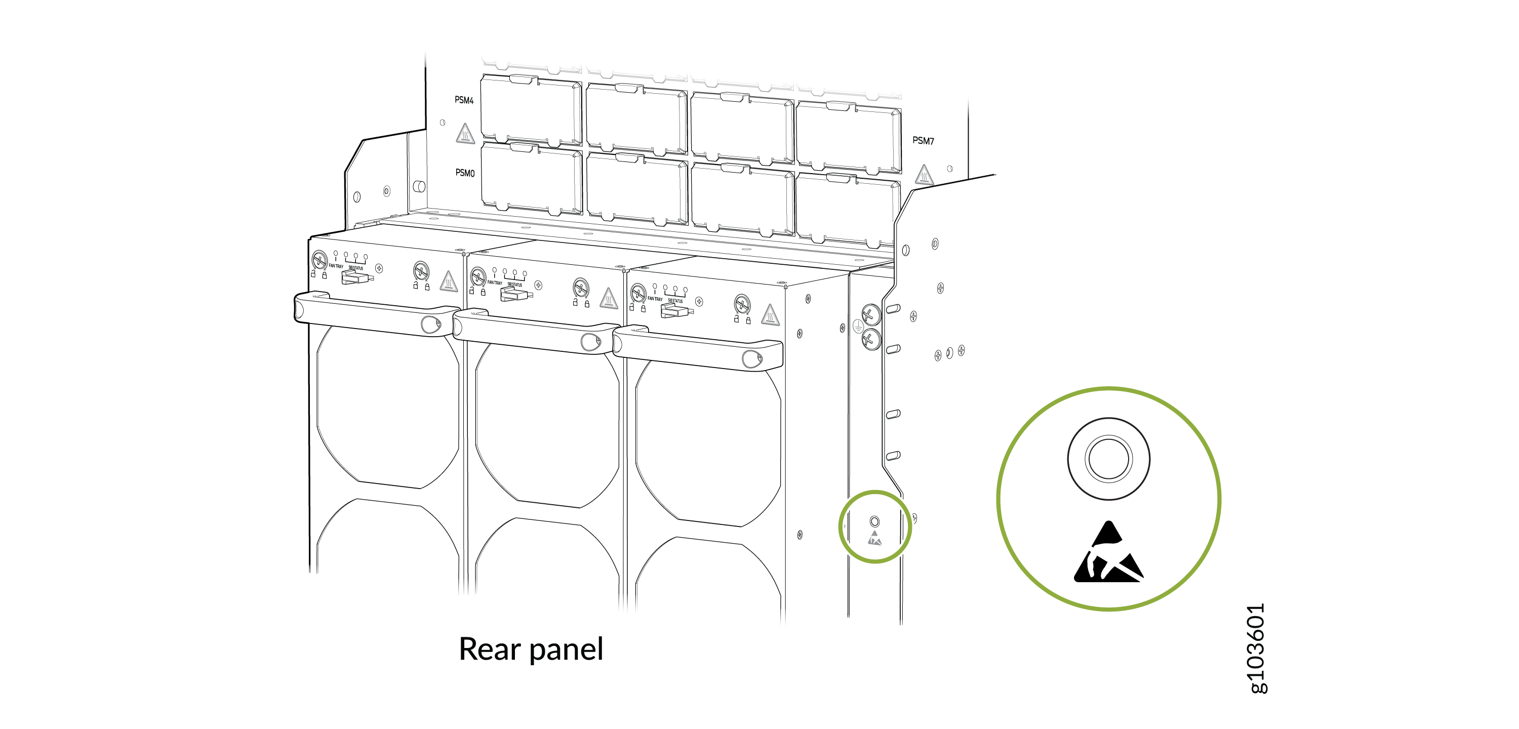
Wrap and fasten one end of the ESD grounding strap around your bare wrist and
connect the other end of the strap to an ESD point on the rear panel of the
chassis.
Figure 1: ESD Point on the Rear Panel of the Chassis
-
Gently pull out the plug end of the power cord connected to the power source
outlet.
CAUTION:The PSM surfaces are hot.
-
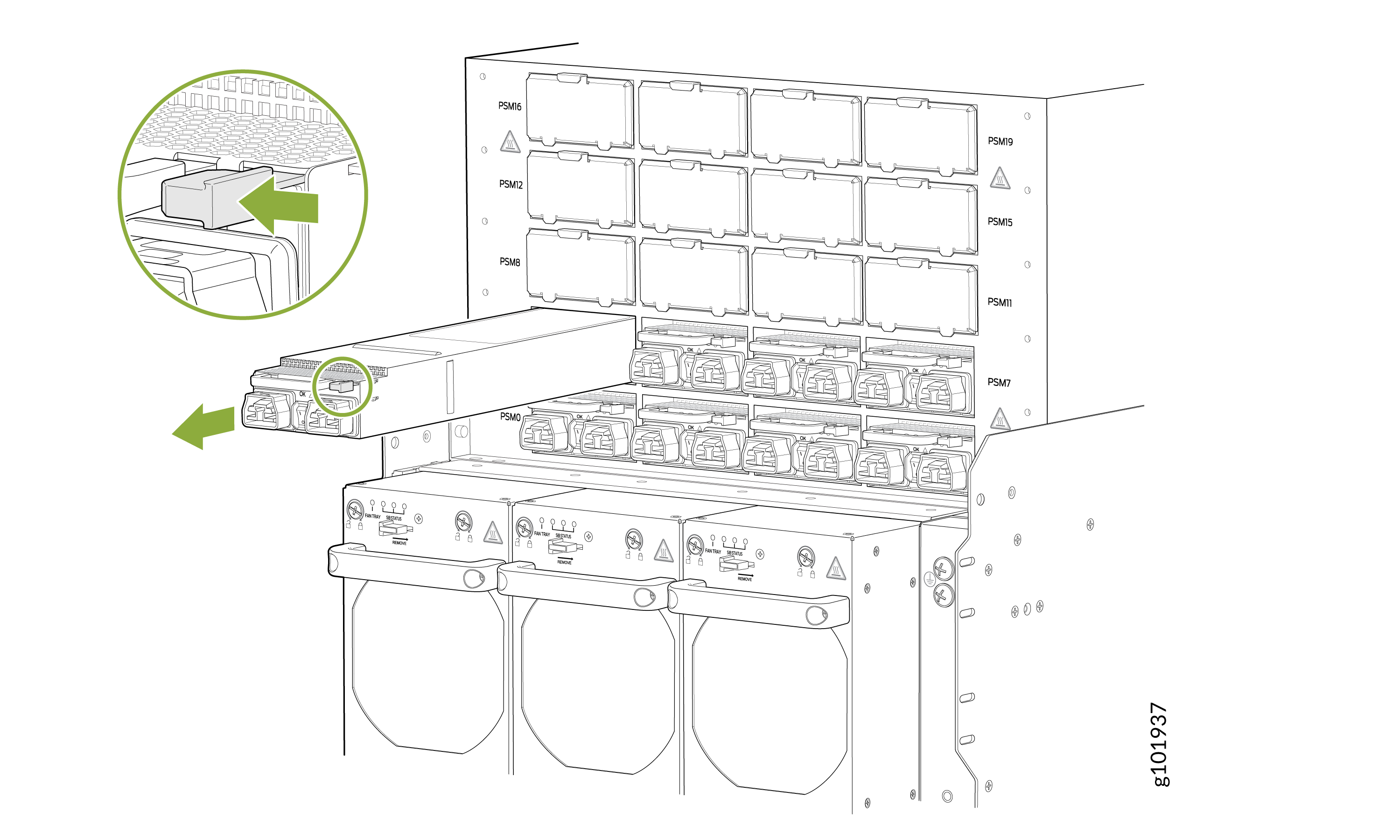
There is a release tab on the power cord end connected to the power source inlet on
the PSM. Press the tab to release the cable from the inlet connector and gently pull
out the power cord.
Install an AC/HVAC/HVDC PSM on the PTX12008 and Connect to Power
You can install an AC/HVAC/HVDC PSM on the PTX12008 and connect it to power by following the following steps.
Before you install an AC/HVAC/HVDC PSM and connect it to power:
-
Ensure that you understand how to prevent ESD damage. See Prevention of Electrostatic Discharge Damage.
-
Ensure that you have the following parts and tools available:
-
An ESD grounding strap—not provided
-
A power cord appropriate for your geographical location—provided. See JNP-PWR-3K-AC PSM Power Cord Specifications and JNP-PWR3K20A-AC PSM Power Cord Specifications.
-
Do not install AC/HVAC/HVDC and DC PSMs in the same chassis at the same time.
For redundancy, always plug the two power cords for each PSM:
-
INP0 into the public electricity supply
-
INP1 into an alternative or independent power source
The router is pluggable type A equipment installed in a restricted-access location. It has a separate protective earthing terminal on the chassis that must be connected to earth ground permanently to ground the chassis adequately and protect the operator from electrical hazards.
You must connect the PSM to a dedicated power source and a dedicated circuit breaker. If you are installing the JNP-PWR-3K-AC, we recommend that you use a customer-site 2-pole circuit breaker rated for 30 A, 300 VAC for HVAC and 30 A, 400 VAC HVDC, or as required by local electrical code. If you are installing the JNP-PWR3K20A-AC, we recommend that you use a customer-site 2-pole circuit breaker rated for 20 A, 300 VAC for HVAC and 20 A, 400 VAC HVDC, or as required by local electrical code.
Before you begin installing the router, ensure that a licensed electrician has attached an appropriate grounding lug to the grounding cable that you supply. Using a grounding cable with an incorrectly attached lug can damage the router.
Route all the PSM cords away from the PSM vents and fan trays. Make sure that the power cords do not obstruct the fan trays or block the air inlets of the chassis. (Optional) Organize and route the power cables attached to the PSMs to prevent them from dislodging or developing stress points by using the power cable management system.
To install an AC/HVAC/HVDC PSM and connect it to power:
-
Wrap and fasten one end of the ESD grounding strap around your bare wrist and
connect the other end of the strap to the ESD point on the rear panel of the
chassis.
Figure 2: ESD Point on the Rear Panel of the Chassis
Note:
You can install the PSMs in any slot labeled PSM0 through PSM19 on the rear panel.
-
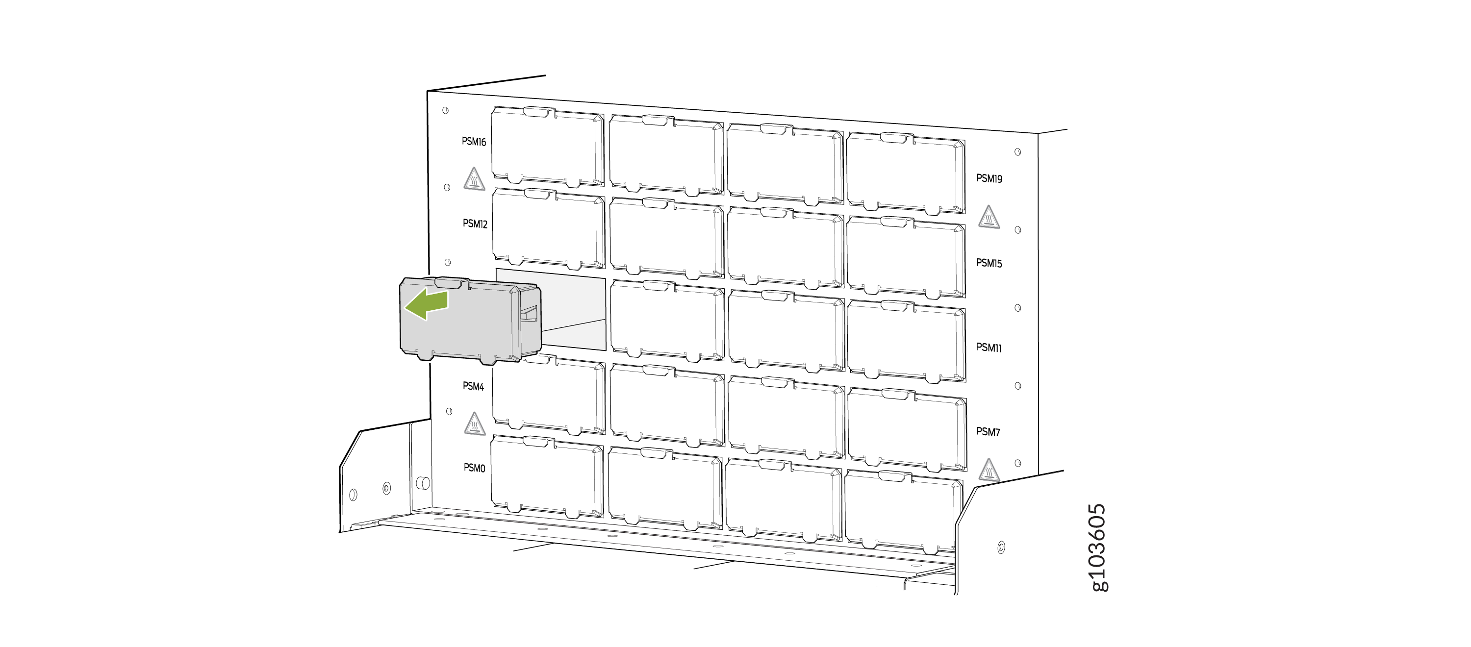
If the PSM slot has a cover on it, pull the cover out of the slot by using your
fingers. Store the cover for later use.
Figure 3: Remove the PSM Slot Cover
-
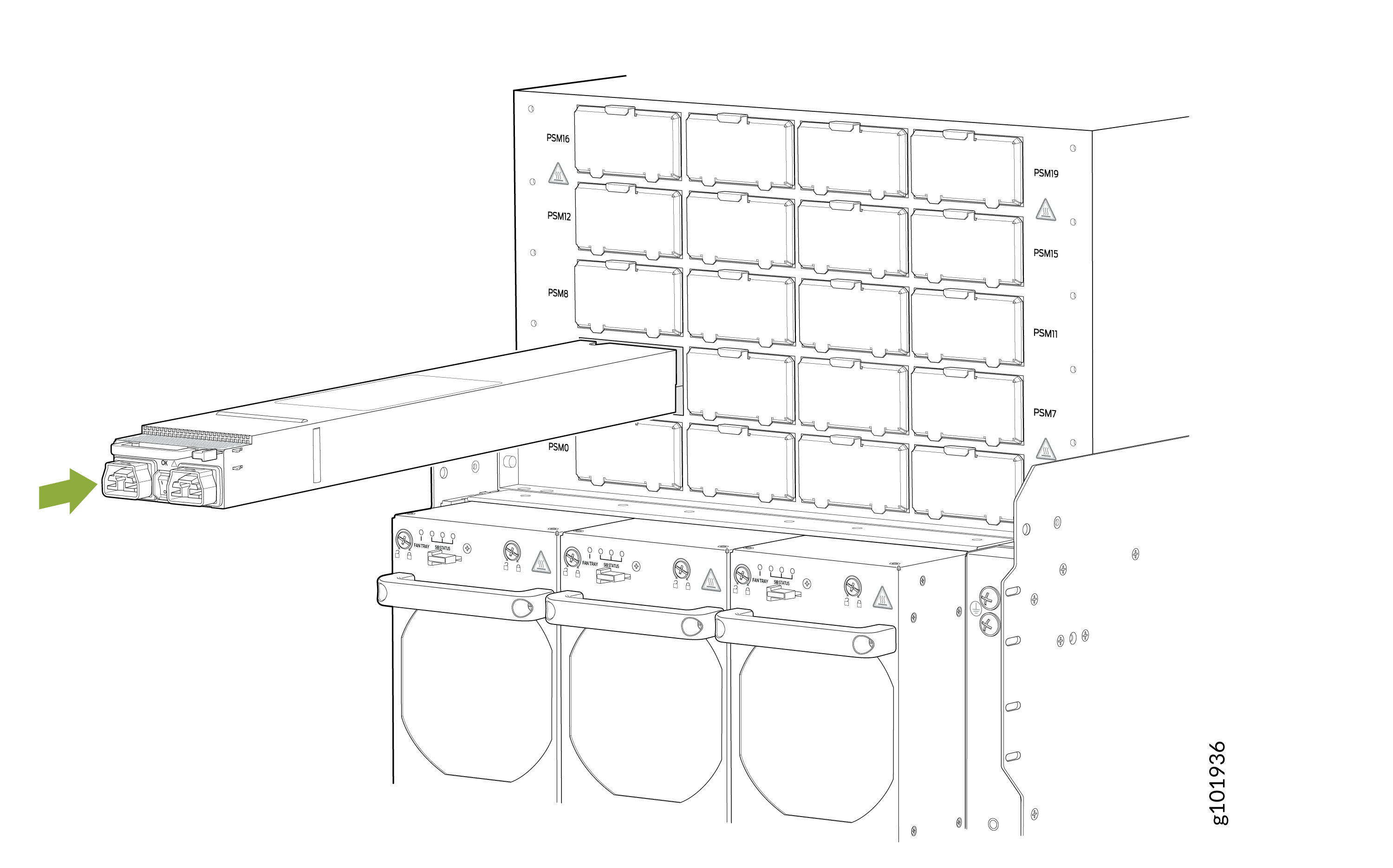
Using both hands, place the PSM straight into the PSM slot on the rear panel of the
chassis.
-
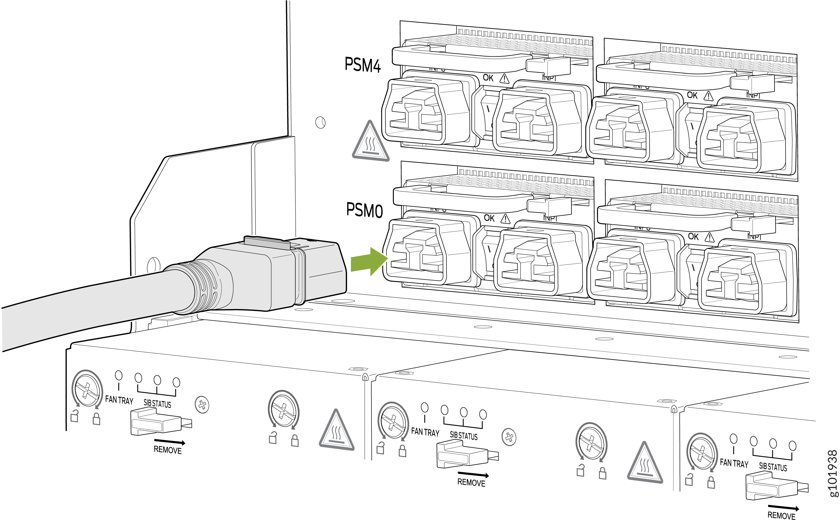
Insert the coupler end of the power cord into the power cord inlet on the PSM
faceplate.
-
Dress the power cord and ensure that it does not touch or block access to other
router components and that it does not drape where people could trip over it.
-
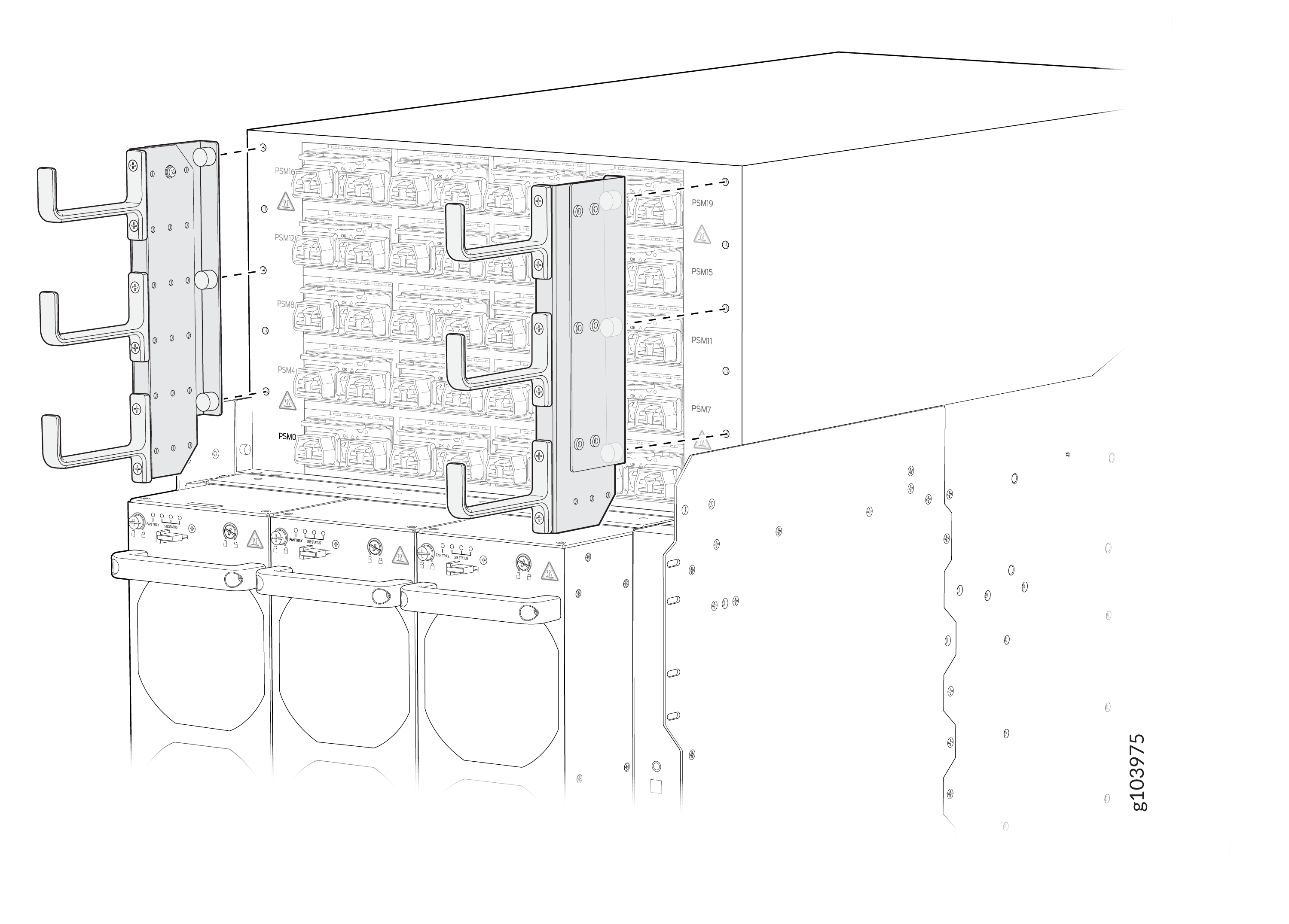
(Optional): Attach the power cable management system. Align the power cable
management system brackets with the holes on either sides of the power shelf
and tighten the screws by using your fingers.
-
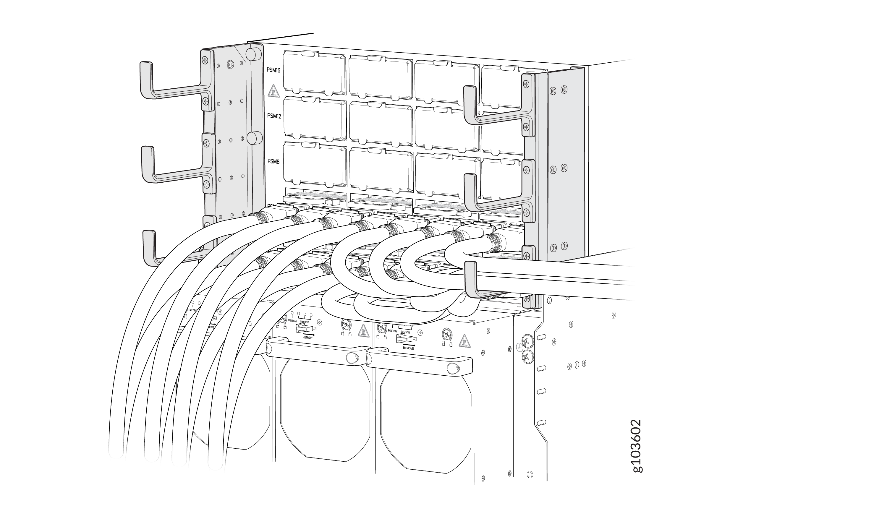
(Optional): Organize and route the power cables attached to the PSMs to
prevent them from dislodging or developing stress points. This step also
ensurea proper airflow through the chassis. Secure the cables so that they are
not supporting their own weight as they hang to the floor. Place excess cables
out of the way in a neatly coiled loop. Placing fasteners on the loop helps to
maintain the cable shape.
-
(Optional): Attach the power cable management system. Align the power cable
management system brackets with the holes on either sides of the power shelf
and tighten the screws by using your fingers.
Remove a DC PSM from the PTX12008
You can remove a DC PSM from the PTX12008 by following the following steps.
Before you remove a DC PSM:
-
Ensure that you understand how to prevent ESD damage. See Prevention of Electrostatic Discharge Damage.
-
Ensure that you have the following parts and tools available:
-
An antistatic bag and an antistatic mat—not provided
-
An ESD grounding strap—not provided
-
A pair of heat-protective gloves—not provided
-
A Phillips (+) screwdriver, number 1—not provided
-
A 13/32-in. (10 mm) nut driver or socket wrench—not provided
-
A replacement PSM or a cover for the PSM slot
-
Before you remove a PSM, ensure that you have PSMs remaining in the chassis sufficient to power the router. See the Power Calculator.
Do not leave the PSM slot empty for a long time while the router is operational. Either replace a PSM promptly or install a cover over the empty slot.
Extreme burn danger—Do not handle a PSM running in the chassis
without wearing heat-protective gloves.
To remove a DC PSM:
-
Wrap and fasten one end of the ESD grounding strap around your bare wrist and
connect the other end of the strap to the ESD point on the rear panel of the
chassis.
Figure 4: ESD Point on the Rear Panel of the Chassis
-
Set the power switch on the PSM to the off (O)
position.
CAUTION:The PSM surfaces are hot.
-
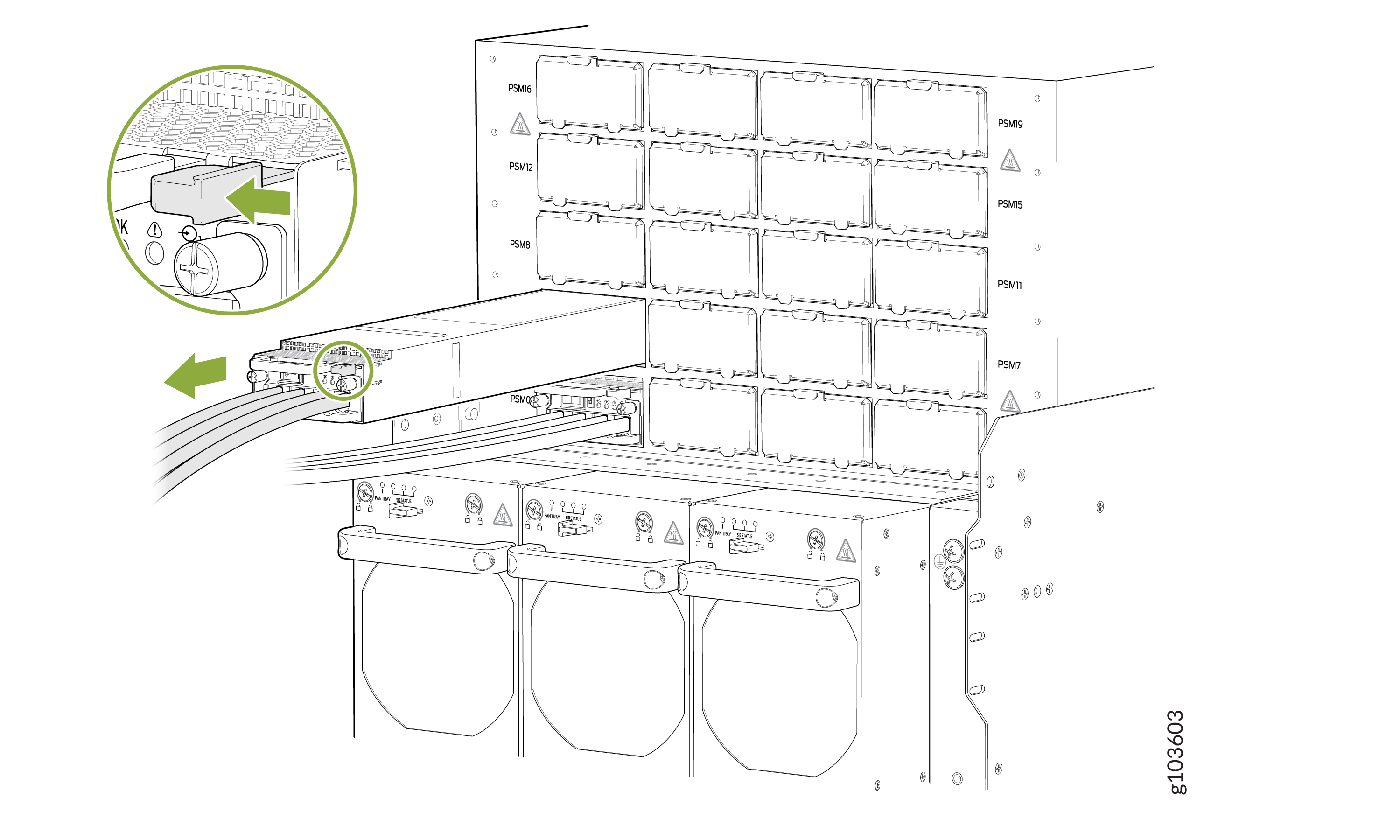
Slide the ejector lever on the PSM toward the PSM handle until the lever
stops.
Install a DC PSM on the PTX12008 and Connect to Power
You can install a DC PSM on the PTX12008 and connect it to power by following the following steps.
Before you install a DC PSM and connect it to power:
-
Ensure that you have followed the following safety warnings and cautions:
Warning:Before performing DC power procedures, ensure that power is removed from the DC circuit. To ensure that all power is off, locate the circuit breaker on the panel board that services the DC circuit, switch the circuit breaker to the off position, and tape the switch handle of the circuit breaker in the off position.
Note:You must connect the battery returns of the DC PSM as an isolated DC return (DC-I).
CAUTION:The PSM requires a dedicated circuit breaker for each input DC feed. Choose a breaker that delivers 80 A (80 V) of input current, or as required by local electrical code.
CAUTION:Before you connect power to the router, ensure that a licensed electrician has attached an appropriate grounding lug to the grounding cable that you supply. Using a grounding cable with an incorrectly attached lug can damage the router (for example, by causing a short circuit).
CAUTION:To meet safety and electromagnetic interference (EMI) requirements and to ensure proper operation, you must connect the chassis to earth ground before you connect to power. For installations that require a separate grounding conductor to the chassis, use the protective earthing terminal on the router chassis to connect to earth ground.
CAUTION:Do not install AC/HVAC/HVDC and DC PSMs in the same chassis at the same time.
Warning:Extreme burn danger—Do not handle a PSM
running in the chassis without wearing heat-protective gloves.Warning:The router has a separate protective earthing terminal on the chassis that must be connected to earth ground permanently to ground the chassis adequately and protect the operator from electrical hazards.
-
Ensure that you understand how to prevent ESD damage. See Prevention of Electrostatic Discharge Damage.
-
Ensure that you have the following parts and tools available:
-
An antistatic bag or an antistatic mat—not provided
-
An ESD grounding strap—not provided
-
DC power source cables (not provided) with the cable lugs (provided) attached
The cable lugs (Panduit LCD4-14A-L or equivalent) are sized for 4-AWG (21.1 mm²) power source cables. When you are using the DC PSMs in the chassis, the DC power source cables that you provide must be 4-AWG (21.1 mm²) stranded wire. We recommend that you install heat-shrink tubing insulation around the crimped section of the power cables and lugs.
The provided terminal lugs for the DC are Panduit LCD4-14A-L, or equivalent, and sized for 4-AWG (21.1 mm²) power source cables. The 4-AWG (21.1 mm²) stranded wire must be rated 90 °C, or according to local electrical code.
-
A 13/32-in. (10 mm) nut driver or socket wrench—not provided
-
A Phillips (+) screwdriver, number 1—not provided
-
A multimeter—not provided
-
To install a DC PSM and connect it to power:
-
Wrap and fasten one end of the ESD grounding strap around your bare wrist and
connect the other end of the strap to an ESD point on the rear panel of the
chassis.
Figure 5: ESD Point on the Rear Panel of the Chassis
-
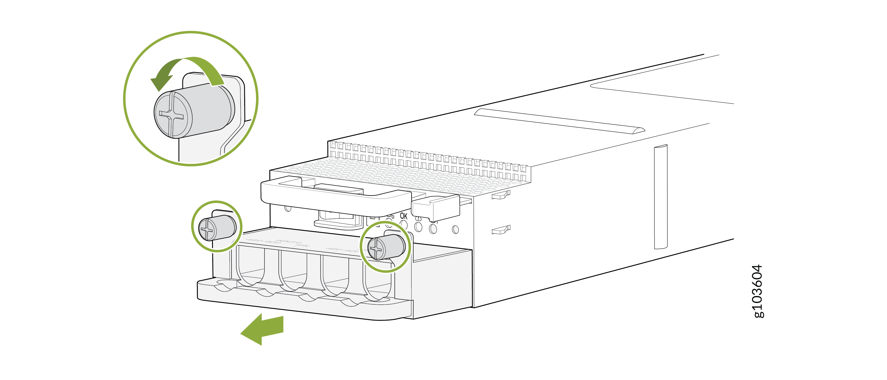
Using the Phillips (+) screwdriver, number 1, loosen the captive screws that secure
the input tray. Hold the input tray handle and gently pull the input tray out of the
PSM.
-
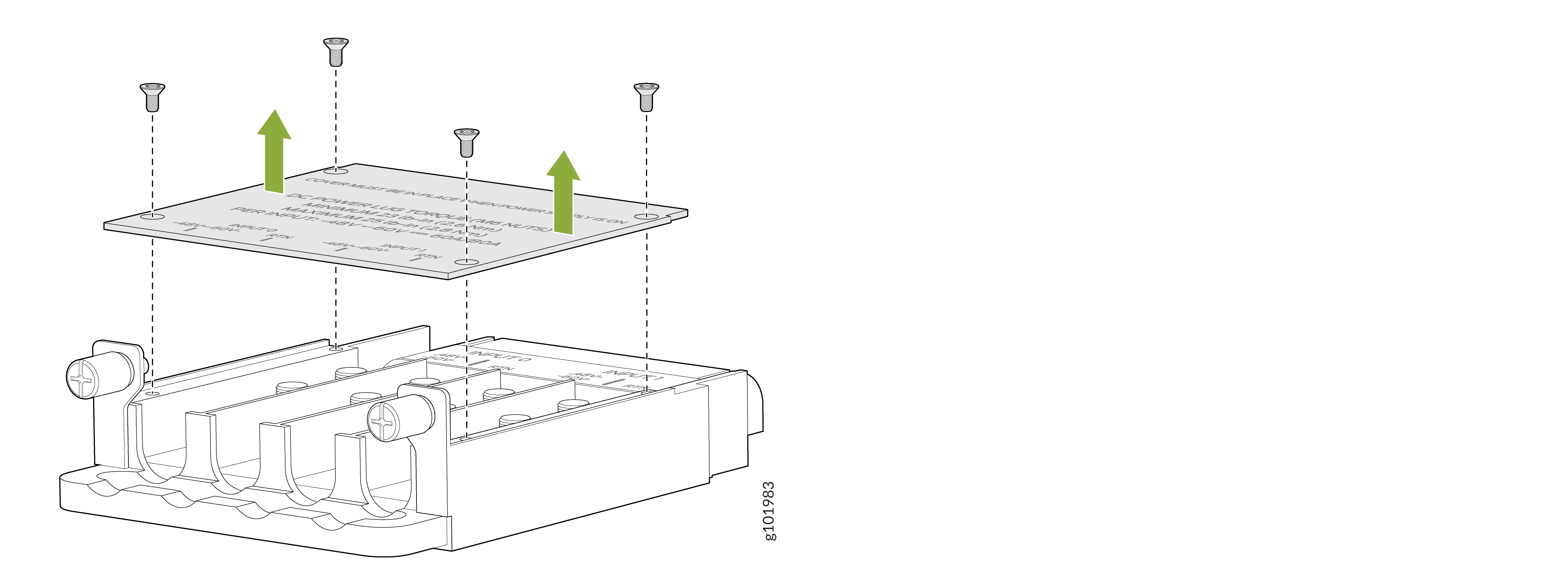
Using the Phillips (+) screwdriver, number 1, loosen the screws that secure the
cover over the input tray and remove the cover.
Figure 6: Remove the Input Tray Cover
-
Install each power cable lug on the DC power input terminal, securing it with the
nuts. Apply between 23 lb-in. (2.6 Nm) and 25 lb-in. (2.8 Nm) of torque to each nut
by using the 13/32-in. (10 mm) nut driver or socket wrench.
-
Secure each positive (+) DC source power cable lug to the RTN (return) DC power input terminal.
-
Secure each negative (–) DC source power cable lug to the –48V (input) DC power input terminal.
Figure 7: Connect the DC Power Source Cables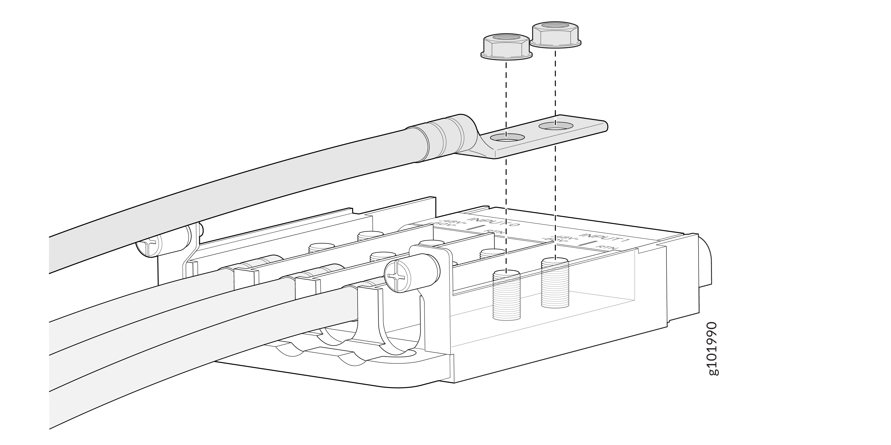
Each PSM has two independent sets of DC power input terminals (INPUT 1: RTN -48V/-60V and INPUT 2: RTN -48V/60V). For feed redundancy, you must power each PSM with dedicated power feeds from INPUT 1 and INPUT 2. This configuration provides the commonly deployed INPUT 1/INPUT 2 feed redundancy for the router. There is basic insulation between the input feeds and the chassis ground and between the RTN input feeds.
-
-
If the PSM slot has a cover on it, pull the cover out of the slot. Store the cover
for later use.
Figure 8: Remove the PSM Slot Cover
-
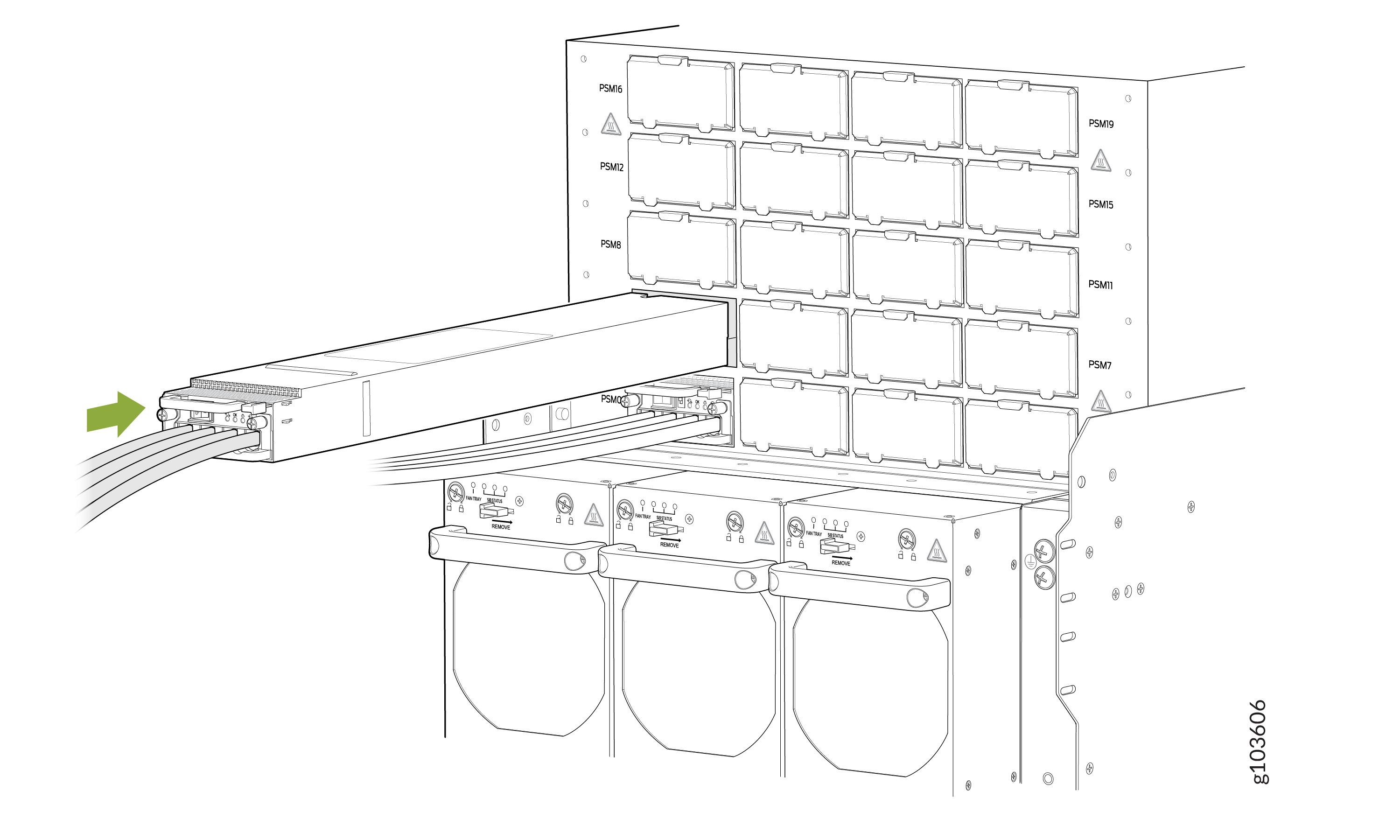
Slide the PSM straight into the chassis until the PSM is fully seated in the slot.
Ensure that the PSM faceplate is flush with any adjacent PSM faceplates or PSM
slot
covers.
Figure 9: Install a DC PSM
 Note:
Note:Ensure that the ejector is fully open, to avoid scratching the chassis.
-
Dress the power cables and ensure that they do not touch or block access to other
router components and that they do not drape where people could trip over them.
-
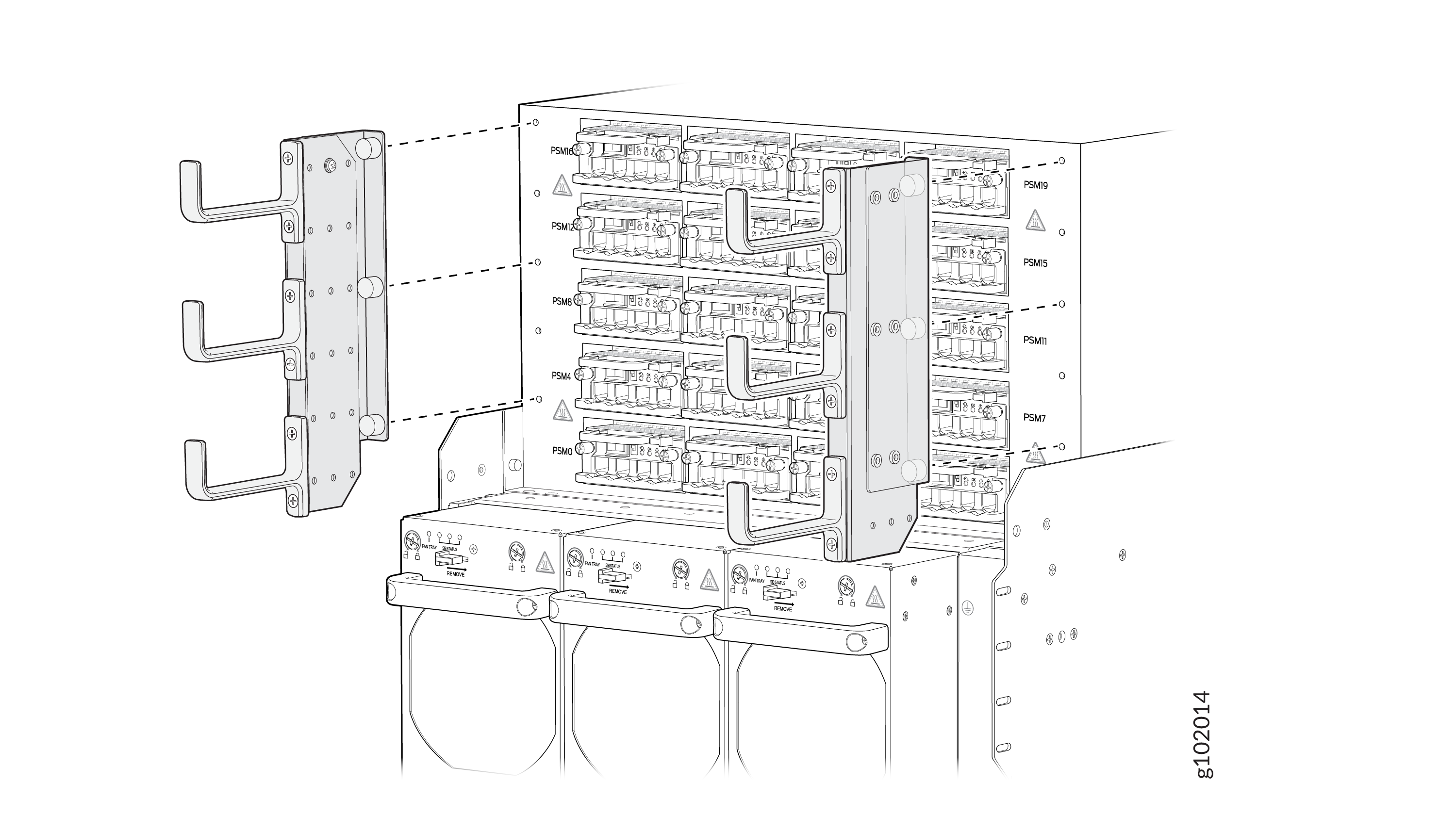
(Optional): Attach the power cable management system. Align the power cable
management system brackets with the holes on either sides of the power shelf
and tighten the screws by using your fingers.
-
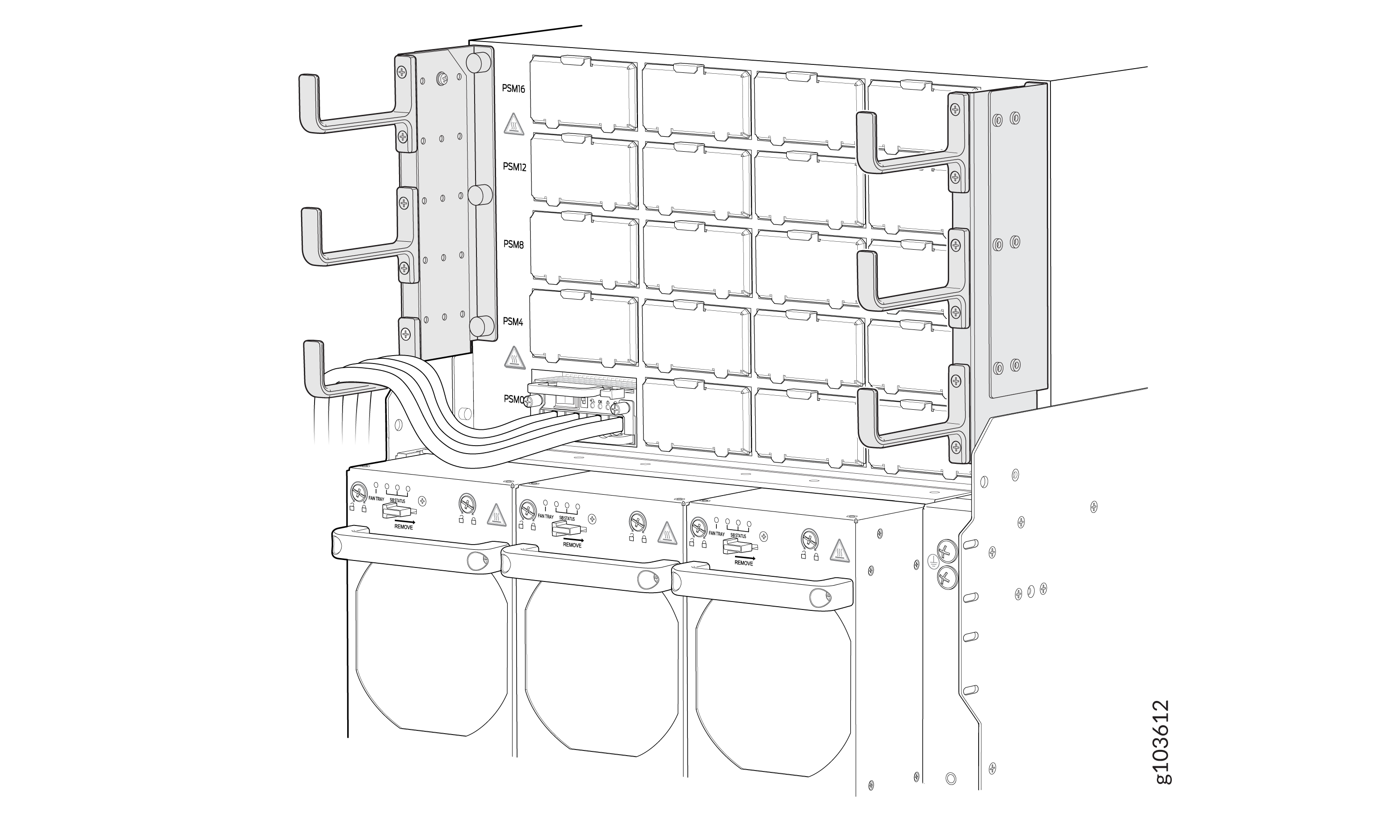
(Optional): Organize and route the power cables attached to the PSMs by using
the power cable management system to prevent them from dislodging or developing
stress points. This step also ensures proper airflow through the chassis.
Secure the cables so that they are not supporting their own weight as they hang
to the floor. Place excess cables out of the way in a neatly coiled loop.
Placing fasteners on the loop helps to maintain the cable shape.
-
(Optional): Attach the power cable management system. Align the power cable
management system brackets with the holes on either sides of the power shelf
and tighten the screws by using your fingers.