PTX12008 Power System
The PTX12008 power system includes AC/HVAC/HVDC and DC power supply modules and related power cords and cables.
The PTX12008 is powered by 20 power supply modules (PSMs).
The router supports the following PSMs:
-
3.7 kilowatt (kW) AC/HVAC/HVDC PSM (model number: JNP-PWR-3K-AC)
-
3 kW AC/HVAC/HVDC PSM (model number: JNP-PWR3K20A-AC)
-
DC PSM (model number: JNP-PWR-3K-DC)
The PSMs are hot-insertable and hot-removable field-replaceable units (FRUs). You can install the PSMs in the PSM slots on the rear panel of the chassis.
Power Shelf
The power shelf provides the housing and electrical connections for the PSMs. It
provides point-to-point connections for power and signal and DC power and
connections between the PSMs and the PTX12008 chassis. 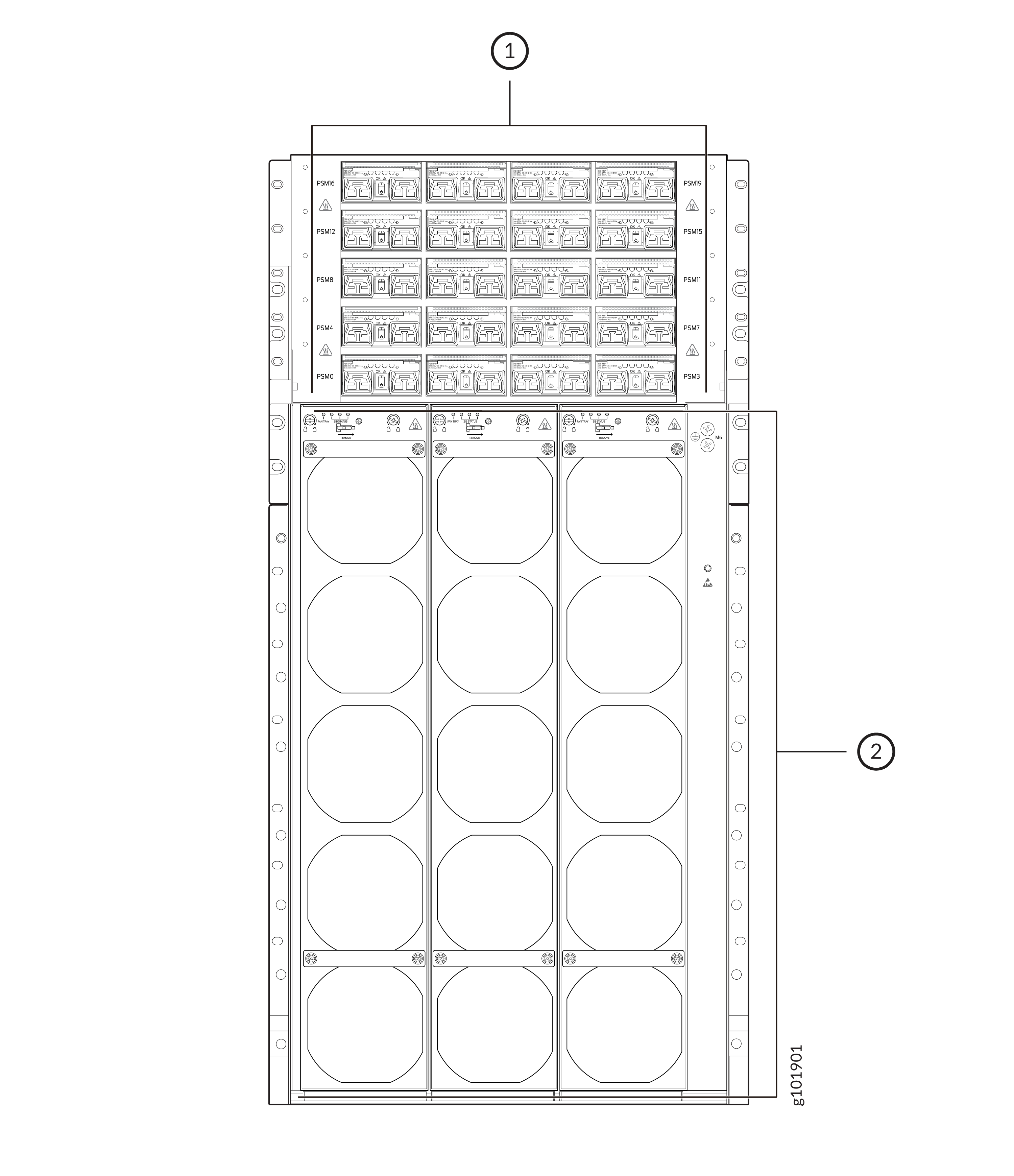
-
Power shelf
-
Fan trays
Table 1 shows the physical specifications of the power shelf.
|
Specification |
Values |
|---|---|
|
Number of PSMs that the power shelf can hold |
20 |
|
PSM numbering |
0 through 19 |
|
Height |
7.91 in. (21 cm) |
|
Width |
17.2 in. (43.7 cm) |
|
Depth |
30 in. (76.2 cm) |
|
Weight |
109 lb (49.4 kg) |
JNP-PWR-3K-AC PSM
Learn about the JNP-PWR-3K-AC PSM used on the PTX12008 and its specifications.
The JNP-PWR-3K-AC PSM supports AC, high-voltage AC (HVAC), or high-voltage DC (HVDC) input. The PSM automatically detects whether there is AC, HVAC, or HVDC input and manages the power accordingly. The PSM provides 3700-watt (W) DC output.
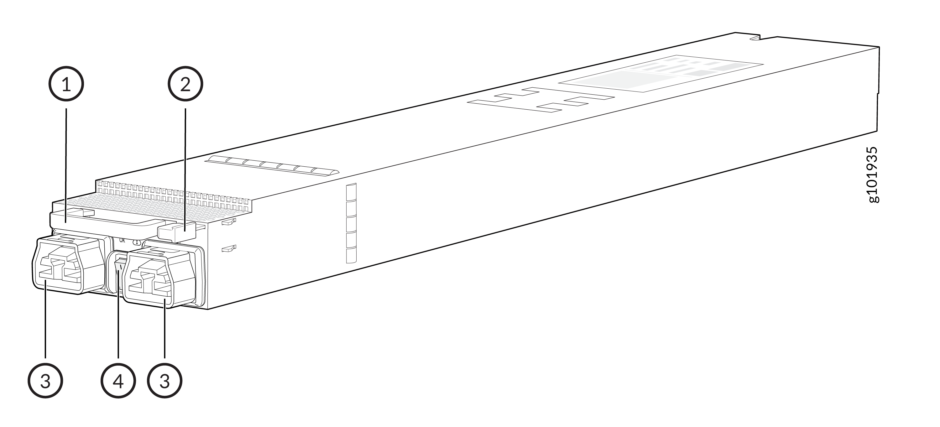
1 — Handle | 3 — AC/HVAC/HVDC inlets |
2 — Ejector lever | 4 — Power switch |
Each PSM has its own built-in fan and is cooled by its own internal cooling system. Hot air exhausts from the rear of the chassis.
Each PSM has two independent 24-Amperes (A) rated AC/HVAC/HVDC inlets on the faceplate. Though each inlet provides sufficient input power to provide full output, always connect both inlets to dedicated AC/HVAC/HVDC power sources to provide redundancy.
Each JNP-PWR-3K-AC PSM has a handle, an ejector lever, a power switch with international markings for on (|) and off (O), two AC/HVAC/HVDC inlets, and four status LEDs on the faceplate.
Table 2 shows the physical specifications of the PSM.
|
Specification |
Values |
|---|---|
|
Height |
1.6 in. (4 cm) |
|
Width |
3.2 in. (8 cm) |
|
Depth |
21 in. (53.3 cm) |
|
Weight |
6.8 lb (3.1 kg) |
JNP-PWR-3K-AC operates within the AC/HVAC/HVDC input voltage range listed in Table 3.
|
Parameter |
Minimum |
Rated |
Maximum |
|---|---|---|---|
|
Input voltage—AC/HVAC |
180 VAC |
200–277 VAC |
305 VAC |
|
Frequency for input—AC/HVAC |
47 Hz |
50-60 Hz |
63 Hz |
|
Input voltage—HVDC |
190 VDC |
240–380 VDC |
410 VDC |
JNP-PWR-3K-AC PSM LEDs
Learn about the LEDs on the JNP-PWR-3K-AC PSM used on the PTX12008.
The JNP-PWR-3K-AC PSM has four LEDs on its faceplate: 0 (INP0), 1 (INP1), OK (Power OK), and ! (Fault). These LEDs display information about the status of the PSM.
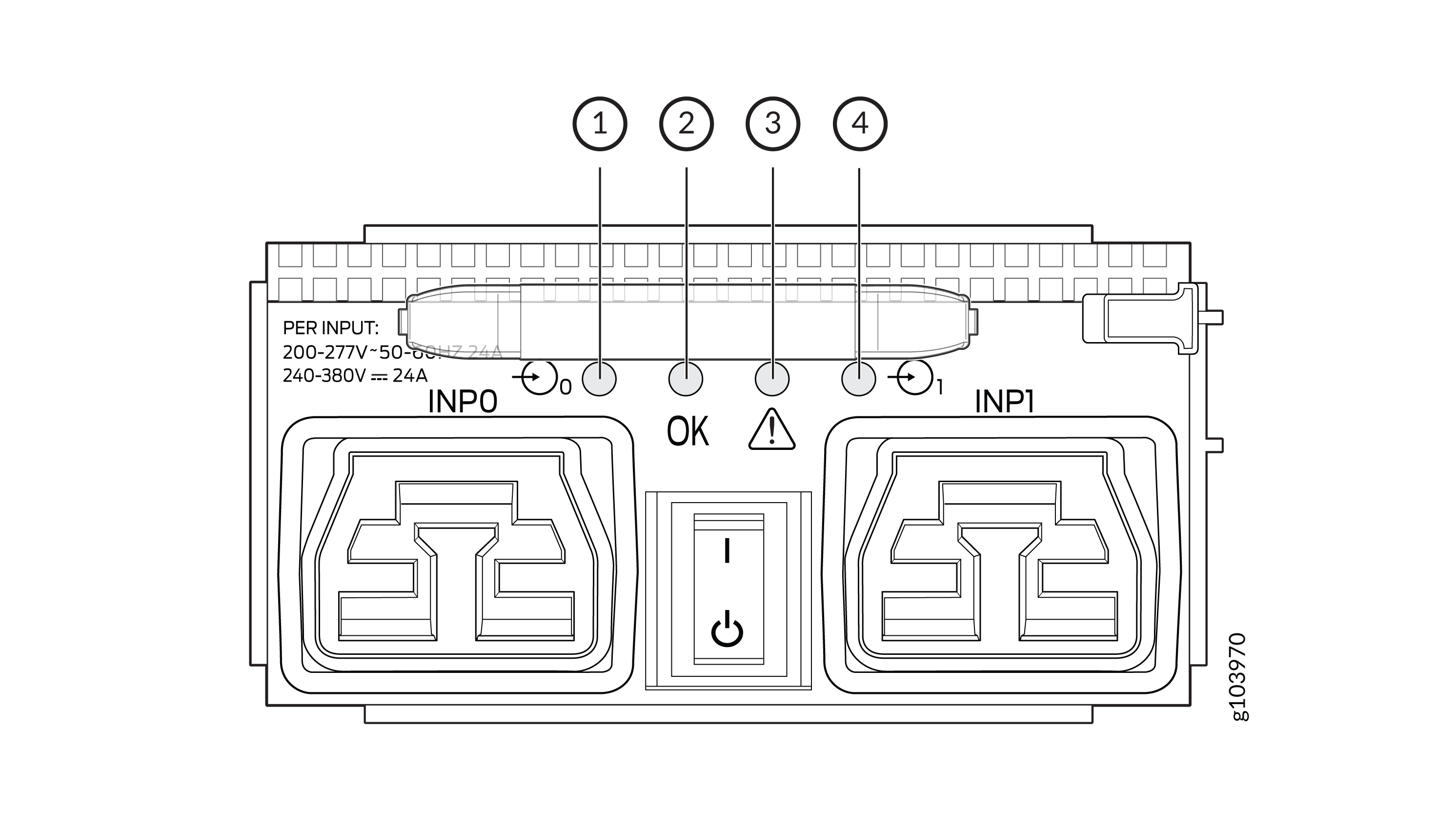
1 — 0 (INP0) LED | 3 — ! (Fault) LED |
2 — OK (Power OK) LED | 4 — 1 (INP1) LED |
|
LED |
Color |
State |
Description |
|---|---|---|---|
|
0 (INP0) and 1 (INP1) |
Green |
Solid |
The input power is within normal operating range. |
|
Amber |
Blinking |
The input power is not within normal operating range. |
|
|
None |
Unlit |
The PSM is switched off; the voltage is zero. |
|
|
OK (Power OK) |
Green |
Solid |
The output power is within normal operating range. |
|
Amber |
Blinking |
The output power is not within normal operating range. |
|
|
! (Fault) |
Red |
Solid |
The PSM has failed; you must replace it. |
|
None |
Unlit |
The PSM is functioning normally. |
You can get additional information about the status of the PSMs by using the show chassis power command.
JNP-PWR-3K-AC PSM Power Cord Specifications
Learn about the power cords for the JNP-PWR-3K-AC PSM used on the PTX12008 and their specifications.
Table 5 lists the specifications of the AC/HVAC power cord provided for each country or region.
|
Power Cord Type |
Locale |
Cord Set Rating |
Plug Standards |
Connector |
Spare Juniper Model Number |
|---|---|---|---|---|---|
|
AC/HVDC power cord |
Any |
30-A, 400 VAC |
UL 950 and IEC 60950 |
Anderson/straight to bare wire |
CBL-PWR2-BARE |
|
30-A, 400 VAC |
UL 950 and IEC 60950 |
Anderson/right-angle to bare wire |
CBL-PWR2-BARE-RA |
||
|
AC power cord |
Continental Europe |
30-A 250 VAC |
UL 950 and IEC332P6 |
Anderson/right-angle to IEC 332P6 |
CBL-PWR2-332P6W-RA |
|
30-A 250 VAC |
UL 950 and IEC332P6 |
Anderson/straight to IEC332P6 |
CBL-PWR2-332P6W |
||
|
North America |
30-A 250 VAC |
IEC330P6 |
Anderson/right-angle to IEC 330P6 |
CBL-PWR2-330P6W-RA |
|
|
30-A 250 VAC |
IEC330P6 |
Anderson/straight to IEC 330P6 |
CBL-PWR2-330P6W |
||
|
30-A 250 VAC |
UL 498, CSA |
Anderson/right-angle to L6-30P (NEMA-30A) |
CBL-PWR2-L6-30P-RA |
JNP-PWR3K20A-AC PSM
Learn about the JNP-PWR3K20A-AC PSM used on the PTX12008 and its specifications.
The JNP-PWR3K20A-AC PSM supports AC, high-voltage AC (HVAC), or high-voltage DC (HVDC) input. The PSM automatically detects whether there is AC, HVAC, or HVDC input and manages the power accordingly. The PSM provides 3000-watt (W) DC output.
1 — Handle | 3 — AC/HVAC/HVDC inlets |
2 — Ejector lever | 4 — Power switch |
Each PSM has its own built-in fan and is cooled by its own internal cooling system. Hot air exhausts from the rear of the chassis.
Each PSM has two independent 16-Amperes (A) rated AC/HVAC/HVDC inlets on the faceplate. Though each inlet provides sufficient input power to provide full output, always connect both inlets to dedicated AC/HVAC/HVDC power sources to provide redundancy.
Each JNP-PWR3K20A-AC PSM has a handle, an ejector lever, a power switch with international markings for on (|) and off (O), two AC/HVAC/HVDC inlets, and four status LEDs on the faceplate.
Table 6 shows the physical specifications of the AC/HVAC/HVDC PSM.
|
Specification |
Values |
|---|---|
|
Height |
1.6 in. (4 cm) |
|
Width |
3.2 in. (8 cm) |
|
Depth |
21 in. (53.3 cm) |
|
Weight |
6.8 lb (3.1 kg) |
JNP-PWR3K20A-AC operates within the AC/HVAC/HVDC input voltage range listed in Table 7.
|
Parameter |
Minimum |
Rated |
Maximum |
|---|---|---|---|
|
Input voltage—AC/HVAC |
180 VAC |
200–277 VAC |
305 VAC |
|
Frequency for input—AC/HVAC |
47 Hz |
50-60 Hz |
63 Hz |
|
Input voltage—HVDC |
190 VDC |
240–380 VDC |
400 VDC |
JNP-PWR3K20A-AC PSM LEDs
Learn about the LEDs on the JNP-PWR3K20A-AC PSM used on the PTX12008.
The JNP-PWR3K20A-AC PSM has four LEDs on its faceplate: 0 (INP0), 1 (INP1), OK (Power OK), and ! (Fault). These LEDs display information about the status of the PSM.

1 — 0 (INP0) LED | 3 — ! (Fault) LED |
2 — OK (Power OK) LED | 4 — 1 (INP1) LED |
|
LED |
Color |
State |
Description |
|---|---|---|---|
|
0 (INP0) and 1 (INP1) |
Green |
Solid |
The input power is within normal operating range. |
|
Amber |
Blinking |
The input power is not within normal operating range. |
|
|
None |
Unlit |
The PSM is switched off; the voltage is zero. |
|
|
OK (Power OK) |
Green |
Solid |
The output power is within normal operating range. |
|
Amber |
Blinking |
The output power is not within normal operating range. |
|
|
! (Fault) |
Red |
Solid |
The PSM has failed; you must replace it. |
|
None |
Unlit |
The PSM is functioning normally. |
You can get additional information about the status of the PSMs by using the show chassis power command.
JNP-PWR3K20A-AC PSM Power Cord Specifications
Learn about the power cords for the JNP-PWR3K20A-AC PSM used on the PTX12008 and their specifications.
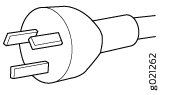
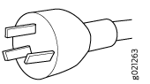
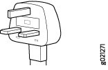
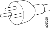
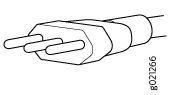
Table 9 lists the specifications of the AC/HVAC power cord provided for each country or region.
|
Locale |
Cord Set Rating |
Plug Standards |
Spare Juniper Model Number |
Graphic |
|---|---|---|---|---|
|
Argentina |
16 A, 250 VAC |
IRAM 2073 Type RA/3 |
CBL-JNP-SG4-AR |

|
|
Australia and New Zealand |
16 A, 250 VAC |
AS/NZS 4417 |
CBL-JNP-SG4-AU |
|
|
Brazil |
16 A, 250 VAC |
NBR 14136 Type BR/3 |
CBL-JNP-SG4-BR |

|
|
China |
16 A, 250 VAC |
GB2099 |
CBL-JNP-SG4-CH |
|
|
China, Europe, and Japan |
16 A, 250 VAC |
C20 to Anderson 3-5958p4 |
CBL-JNP-SG4-C20-CH |

|
|
Europe (except Italy, Switzerland, and United Kingdom) |
16 A, 250 VAC |
CEE 7/7 STRAIGHT |
CBL-JNP-SG4-EU |

|
|
Great Britain |
16 A, 250 VAC, |
BS1363 |
CBL-JNP-SG4-UK |
|
|
India |
16 A, 250 VAC |
SANS 164/1 |
CBL-JNP-SG4-SA |

|
|
Israel |
16 A, RA, 250 VAC |
SI 32/1971 Type IL/3G |
CBL-JNP-SG4-IL |
|
|
Italy |
16 A, 250 VAC |
CEI 23-16 |
CBL-JNP-SG4-IT |
|
|
Japan |
16 A, 250 VAC |
Nema L-20 |
CBL-JNP-SG4-JPL |

|
|
North America |
20 A, 250 VAC |
C20 to Anderson 3-5958p4 |
CBL-JNP-SG4-C20 |

|
|
North America |
20 A, 250 VAC |
Locking NEMA L6-20P |
CBL-JNP-SG4-US-L |
|
|
North America |
20 A, 250 VAC |
NEMA 6-20P |
CBL-JNP-SG4-US |

|
|
North America |
20 A, 277 V |
NEMA L7-20P |
CBL-JNP-SG4-HVAC |

|
|
South Africa |
16 A, 250 VAC |
SANS 164/1 |
CBL-JNP-SG4-SA |
|
|
Switzerland |
16 A, 250 VAC |
CEI 23-50 |
CBL-JNP-SG4-SZ |
|
Table 10 lists the specifications of the HVDC power cord.
|
Cord Set Rating |
Spare Juniper Model Number |
|---|---|
|
16 A, 400 HVDC |
CBL-PWR2-BARE |
JNP-PWR-3K-DC PSM
Learn about the JNP-PWR-3K-DC PSM used on the PTX12008 and its specifications.
The JNP-PWR-3K-DC PSM can operate with an input current of either 60 A or 80 A. The PSM has two independent pairs of DC input lugs (labeled Input 0, RTN, –48V/–60V and Input 1, RTN, –48V/–60V) on the faceplate of the PSM. Each inlet requires a dedicated DC power feed. You must always connect each of inlet the PSM to a dedicated DC power feed to provide redundancy. Only one power feed is operational at a time. You can configure the input using a dual inline package (DIP) switch on the PSM faceplate.
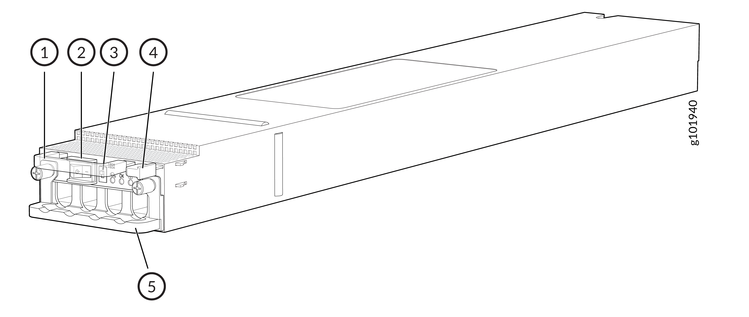
1 — Handle | 4 — Ejector lever |
2 — Power switch | 5 — Input tray handle |
3 — DIP switch |
Each PSM has its own built-in fan and is cooled by its own internal cooling system. Hot air exhausts from the rear of the chassis.
Each JNP-PWR-3K-DC PSM has a handle, a power switch with international markings for on (|) and off (O), a dual inline package (DIP) switch, an ejector lever, an input tray, and four status LEDs on the faceplate.
Table 11 shows the physical specifications of the DC PSM.
|
Specification |
Values |
|---|---|
|
Height |
1.6 in. (4 cm) |
|
Width |
3.2 in. (8 cm) |
|
Depth |
21 in. (53.3 cm) |
|
Weight |
5.1 lb (2.3 kg) |
Table 12 provides the specifications of the DC PSMs.
|
Item |
Specification |
|---|---|
|
Input voltage |
Rated operating voltage: –48 VDC |
|
Input current rating |
60 A |
JNP-PWR-3K-DC PSM LEDs
Learn about the LEDs on the JNP-PWR-3K-DC PSM used on the PTX12008.
The JNP-PWR-3K-DC PSM has four LEDs on its faceplate: 0 (INP0), 1 (INP1), OK (Power OK), and ! (Fault). These LEDs display information about the status of the PSM.

1 — 0 (INP0) LED | 3 — ! (Fault) LED |
2 — OK (Power OK) LED | 4 — 1 (INP1) LED |
|
LED |
Color |
State |
Description |
|---|---|---|---|
|
0 (INP0) and 1 (INP1) |
Green |
Solid |
The input power is within normal operating range. |
|
Yellow |
Blinking |
The input power is not within normal operating range. |
|
|
Unlit |
Off |
The PSM is switched off; the voltage is zero. |
|
|
OK (Power OK) |
Green |
Solid |
The output power is within normal operating range. |
|
Yellow |
Blinking |
The output power is not within normal operating range. |
|
|
! (Fault) |
Red |
Solid |
The PSM has failed; you must replace it. |
|
Unlit |
Off |
The PSM is functioning normally. |
You can get additional information about the status of the PSMs by using the show chassis power command.