Fast Track to Rack Installation and Power
This procedure guides you through the simplest steps to install your EX5200 Switch in a rack and connect it to power. Have more complex installation needs? See Install the EX5200 Switch.

Install the EX5200 Switch in a Rack
You can install the EX5200 switch in a two-post rack, four-post rack or on a wall. We’ll walk you through the steps to install an AC-powered device in a two-post rack (default mounting option). You will use a tool-less mounting procedure.
Before you install, review the following:
-
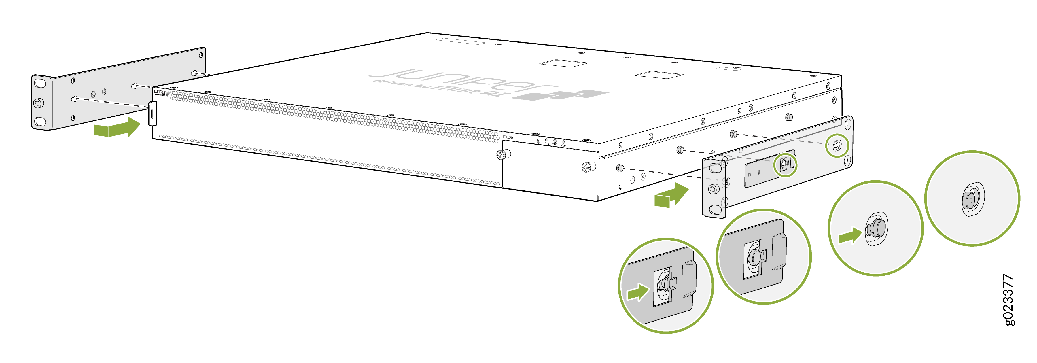
Attach the side-mounting brackets to the chassis. Align the keyholes of the
mounting brackets over the shoulder screws of the chassis. Slide the
mounting brackets toward the rear of the chassis.
-
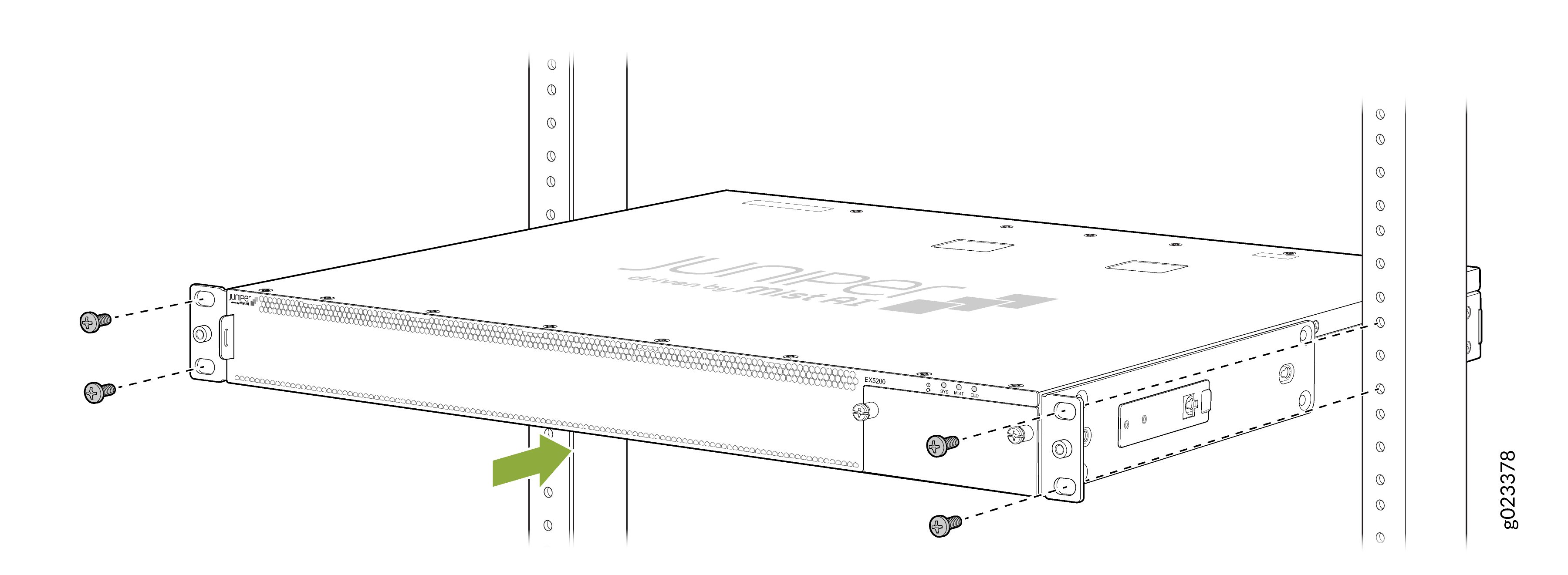
Have a second person secure the mounting brackets to the rack by using four
screws appropriate for your rack.
-
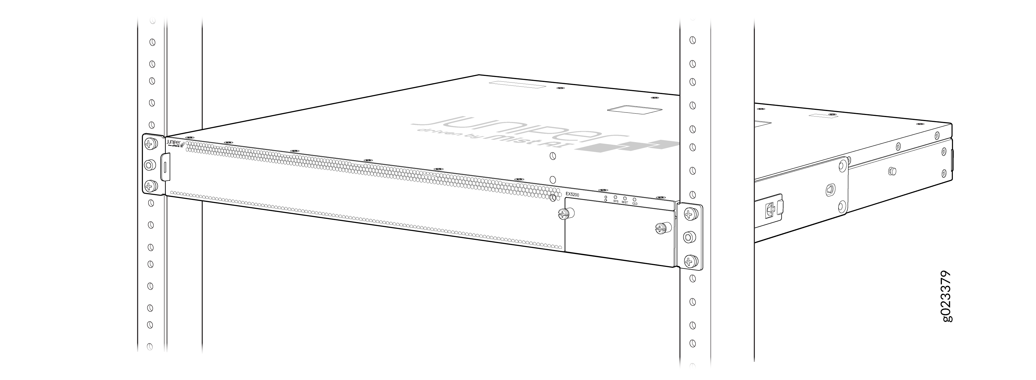
Secure the chassis to the rack'.
Connect to Power
To connect the EX5200 switch to AC power, you must perform the following tasks:
14-10 AWG, minimum 90° C wire, or as permitted by the local code, with a Panduit LCD10-10AF-L or equivalent lug attached.
Ground the EX5200 Switch
To ground the EX5200 Switch:
Wrap and fasten one end of the electrostatic discharge (ESD) cable grounding strap around your bare wrist, and connect the other end to a site ESD point.
Connect the grounding cable to a proper earth ground, such as the rack in which you mount the device.
Place the grounding lug attached to the grounding cable over the protective earthing terminal on the rear panel.
Secure the grounding lug to the protective earthing terminal using screws.
Dress the grounding cable. Be sure that the cable doesn’t block access to or touch other device components, and that it doesn’t drape where people could trip over it
Connect the Power Cord and Power On the EX5200 Switch
For information about the supported AC power cord specifications on your device, see EX5200 Switch Power System.
To connect the power cord:
Wrap and fasten one end of the ESD wrist strap around your bare wrist, and connect the other end of the strap to a site ESD point.
Ensure that the power supply unit (PSU) is fully inserted in the rear panel of the switch.
Locate the power cord or cords shipped with the switch; the cords have plugs appropriate for your geographical location.
Warning:Ensure that the power cord does not block access to device components or drape where people can trip on it.
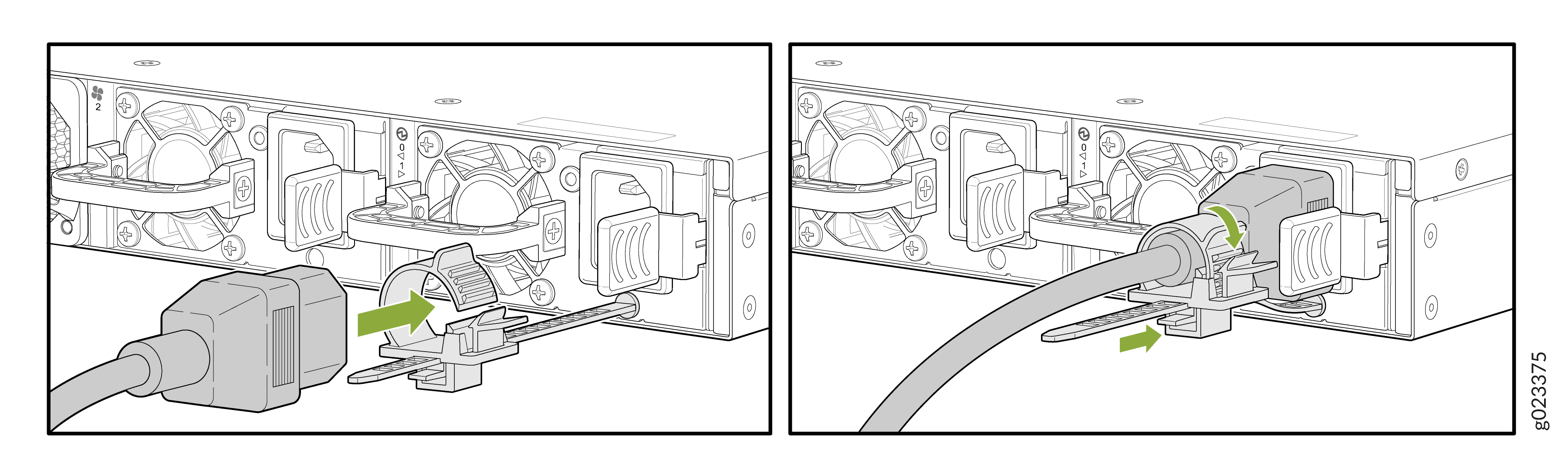
Push the end of the retainer strip into the hole below the inlet on the PSU faceplate until it snaps into place. Ensure that the loop in the retainer strip points upward.
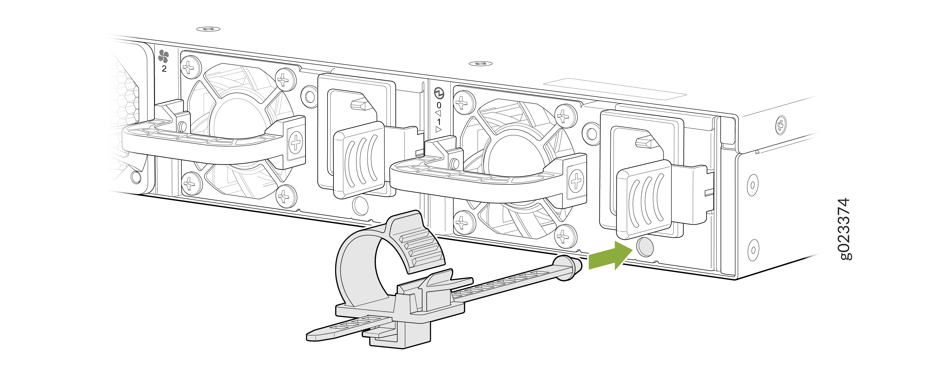
Press the small tab on the retainer strip to loosen the loop. Slide the loop until you have enough space to insert the power cord coupler into the inlet.
Insert the power cord coupler firmly into the inlet.
Slide the loop toward the PSU until it is snug against the base of the power cord coupler.
Press the tab on the loop and draw out the loop into a tight circle
If the AC power source outlet has a power switch, set it to the off position.
Insert the power cord plug into the AC power source outlet. The switch powers on as soon as power is provided to the power supply. There is no power switch on the EX5200.
If the AC power source outlet has a power switch, set it to the on position.
Verify that the OUT.OK LED on the power supply is lit steadily green. If it is not lit steadily green, disconnect the power supply from the power source, and replace the power supply (see Maintain the EX5200 Power System).
-
CAUTION:
Do not remove the power supply until you have a replacement power supply ready: you must install the replacement power supply within one minute after removing the failed power supply to ensure proper airflow and prevent chassis overheating.