Install the EX5200 Switch
This topic guides you through the steps to install the EX5200 switch on walls, two-post racks, and four-post racks.
You can mount the EX5200 switch on a wall, a two-post rack, or a four-post rack. Use the rack mount kit shipped with the device.
Complete these prerequisites before you mount the device:
-
Prepare the site for installation as described in Site Electrical Wiring Guidelines.
-
Ensure that the site has adequate clearance for both airflow and hardware maintenance.
-
Unpack the device as described in Unpack the EX5200 Switch.
Ensure that you support the rear of the chassis throughout the process of mounting the appliance on the rack.
A qualified technician must verify that the rack or cabinet is strong enough to support the device's weight before mounting the device. Have the technician also verify that the rack or cabinet has adequate support at the installation site.
If you are installing more than one device on a rack or in a cabinet, install the first device at the bottom of the rack.
Update Base Installation Data
Update the installation base data if any addition or change to the installation base occurs or if the installation base is moved. Juniper Networks is not responsible for not meeting the hardware replacement SLA for products that do not have accurate installation base data. Update your installation base at https://supportportal.juniper.net/s/CreateCase
Install the EX5200 Switch on a Two Post Rack
We’ll walk you through the steps to install an AC-powered switch in a two post rack.
Wrap and fasten one end of the ESD cable grounding strap around your bare wrist. Connect the other end to a site ESD point.
Attach the side-mounting brackets to the chassis. Align the keyholes of the mounting brackets over the shoulder screws of the chassis. Slide the mounting brackets toward the rear of the chassis.
Figure 1: Attach the side-mounting brackets to the chassis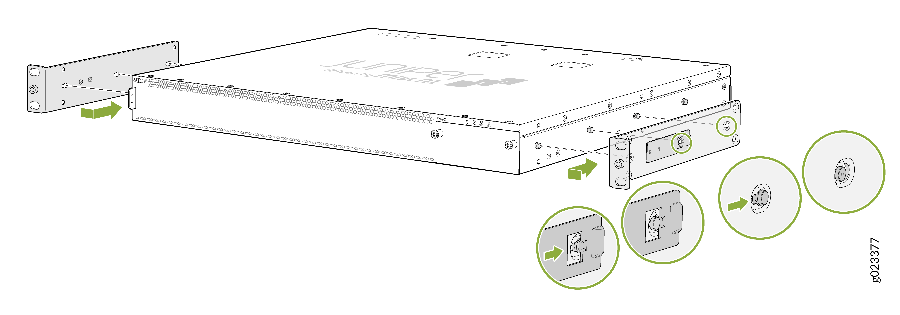
Have one person grasp both sides of the switch, lift the switch, and position it in the rack, aligning the holes of the mounting brackets with the threaded holes in the front post of the rack. Align the bottom hole in both the mounting brackets with a hole in each rack rail, making sure that the chassis is level.
Have a second person secure the mounting brackets to the rack by using four screws appropriate for your rack.
Figure 2: Install the switch chassis into the rack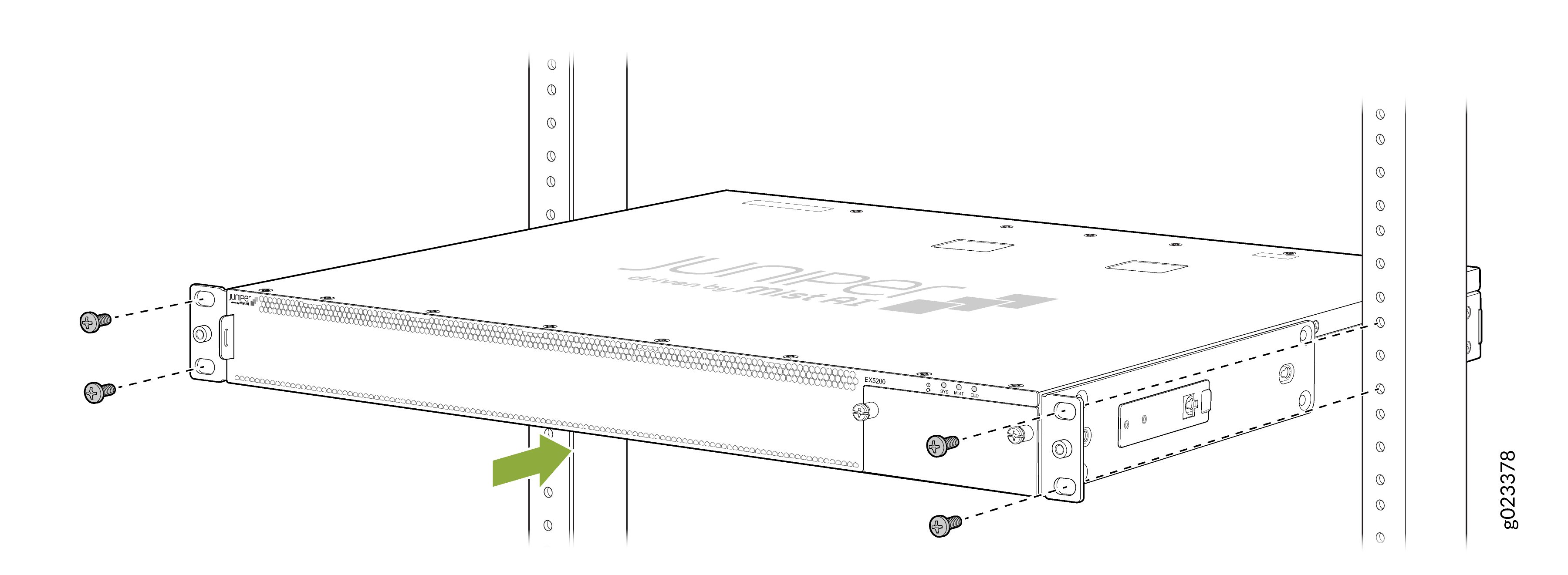
Secure the chassis to the rack
Figure 3: Secure the chassis to the rack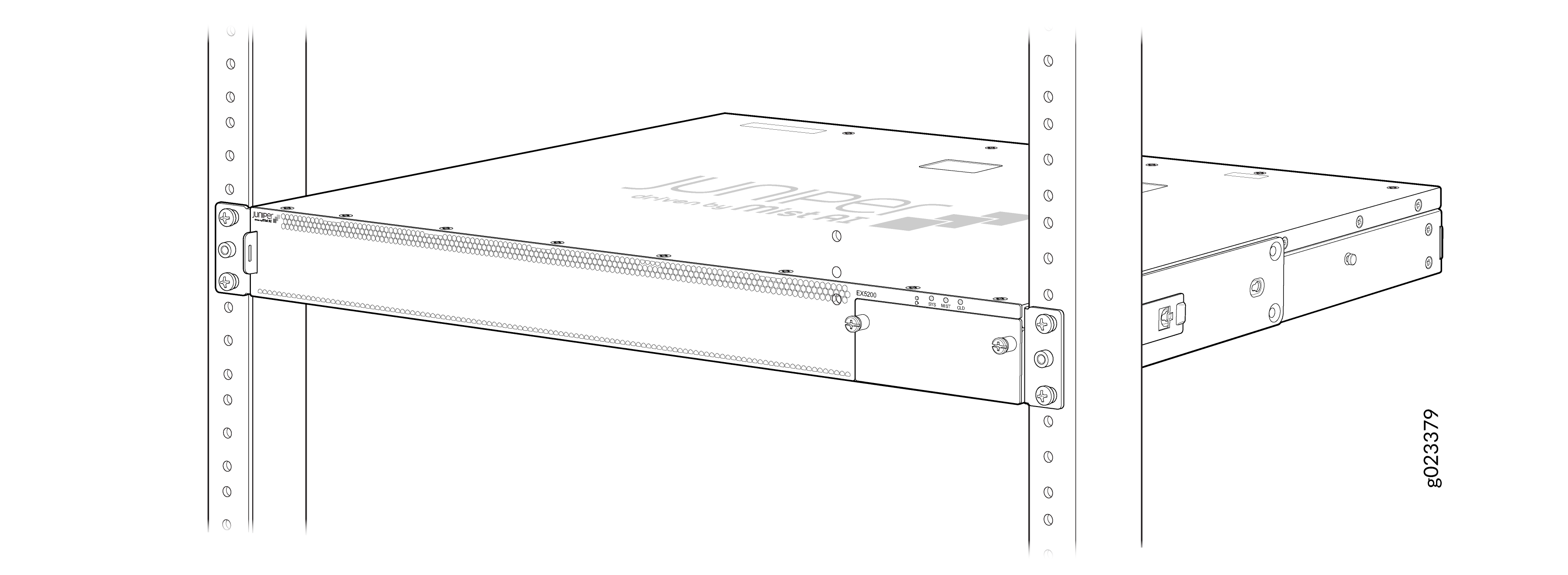
Install the EX5200 Switch on a Square-Holed Four Post Rack
We’ll walk you through the steps to install an AC-powered switch in a square-hole four-post rack.
Wrap and fasten one end of the ESD cable grounding strap around your bare wrist. Connect the other end to a site ESD point.
Attach the side-mounting brackets to the chassis. Align the keyholes of the mounting brackets over the shoulder screws of the chassis. Slide the mounting brackets toward the rear of the chassis.
Figure 4: Attach side-mounting brackets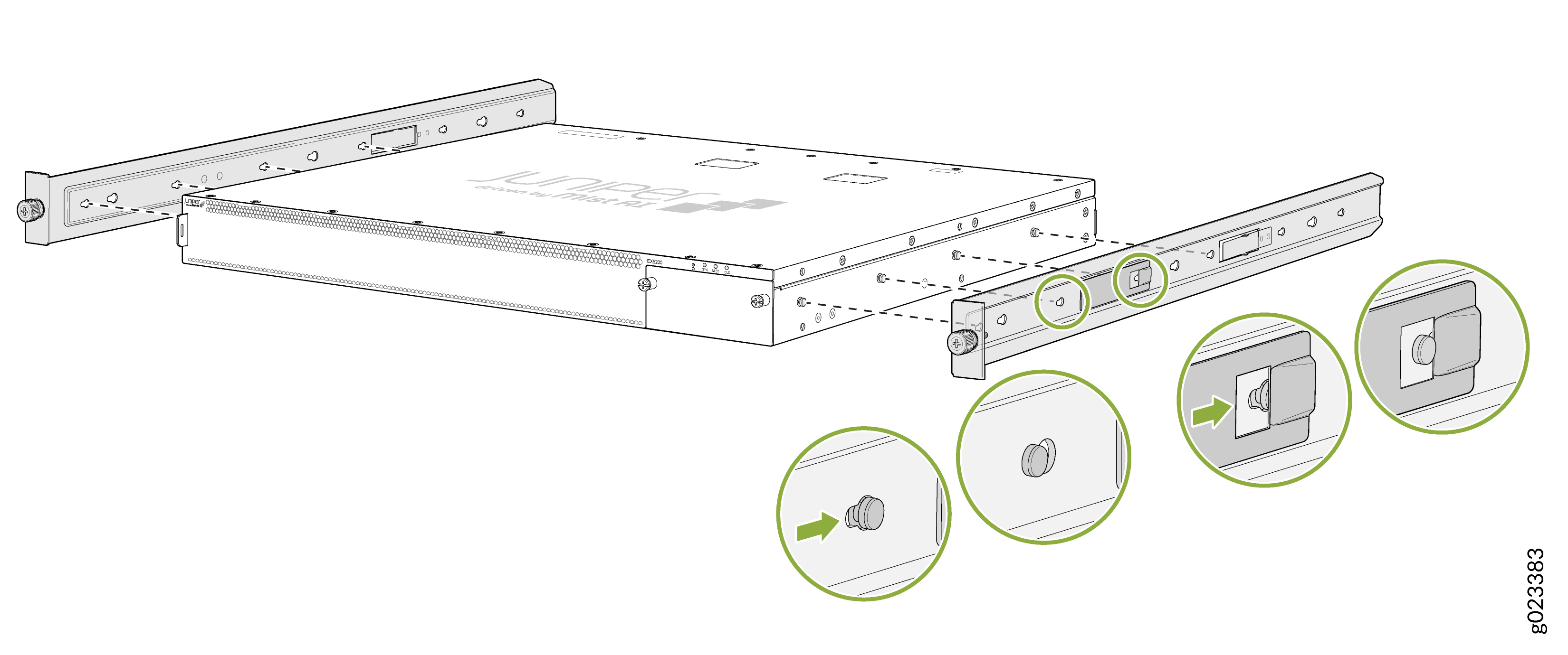
Assemble the mounting rails by sliding the rear rails into the front rails.
Figure 5: Assemble the mounting rails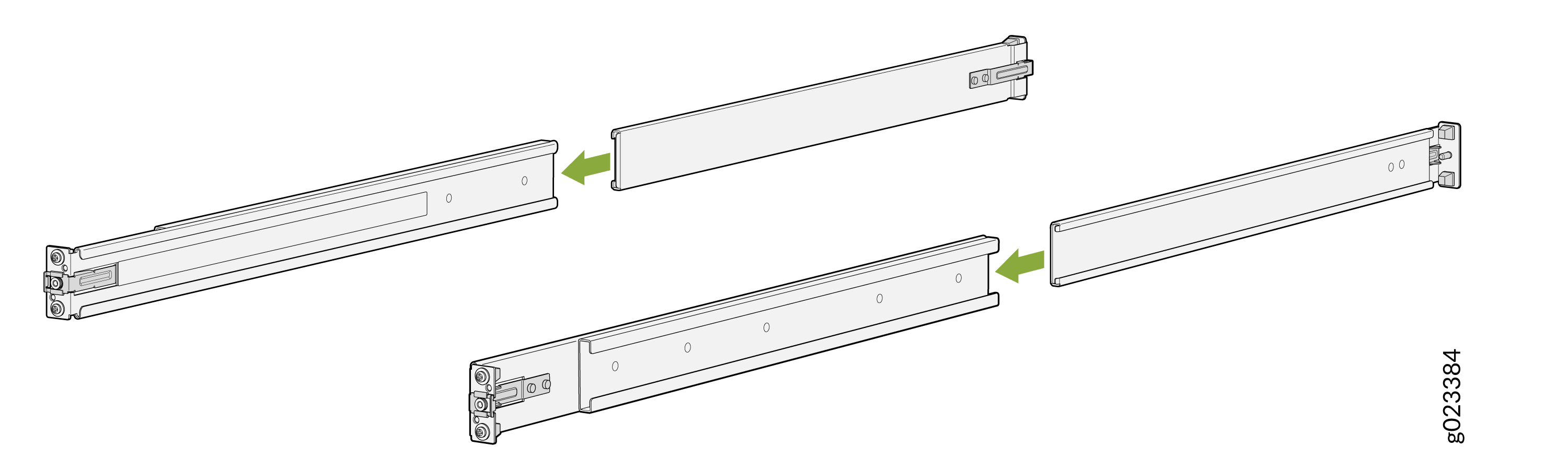
Align the guide blocks of the rear-mounting rail with the rear-post holes. Pull the rear-mounting rail toward the front of the rack to lock the rail in place. You'll hear a distinct click when the latch locks into the rack holes.
Figure 6: Align the guide blocks rear-mounting rail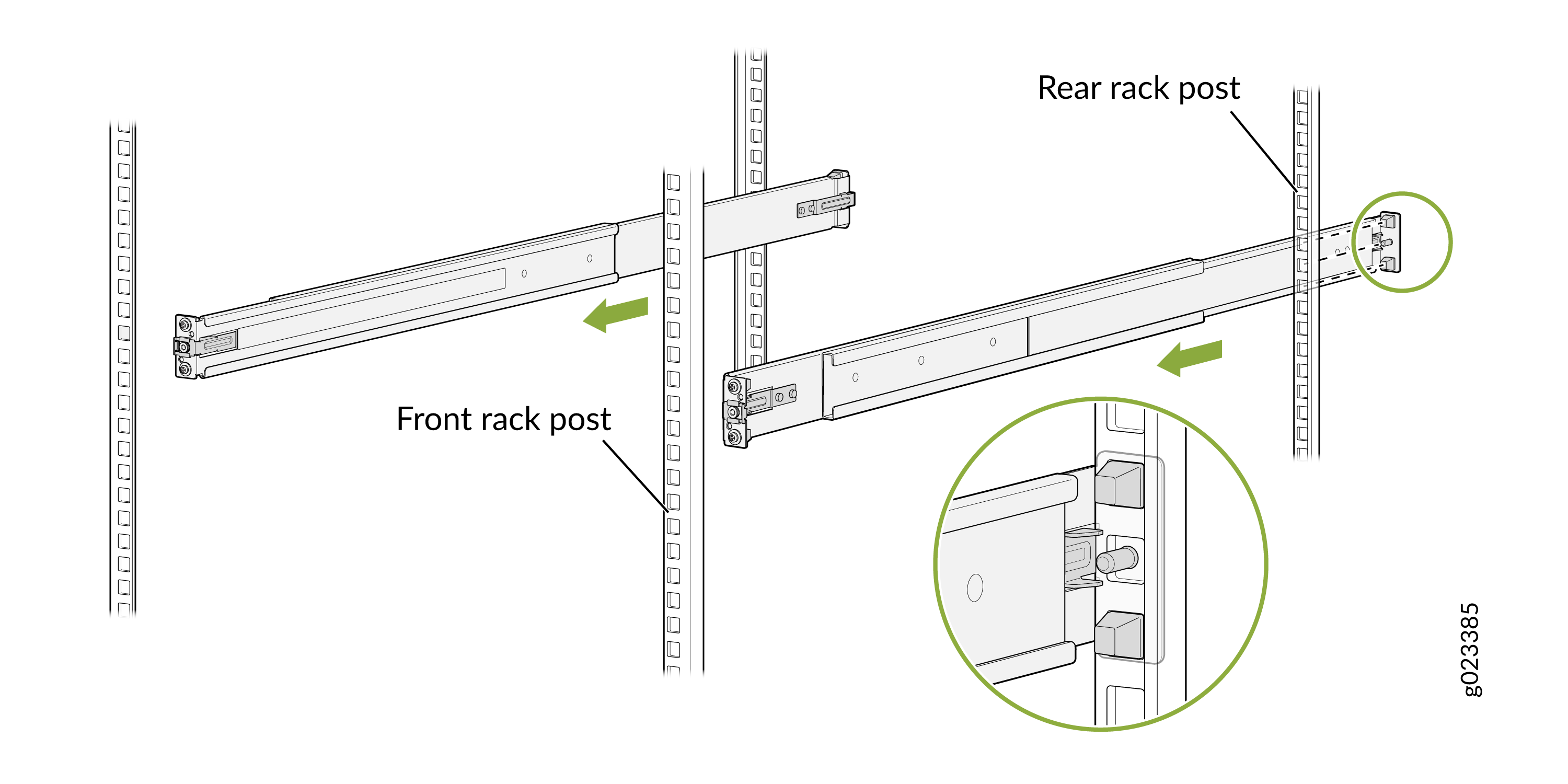
Align the guide blocks of the front-mounting rail with the front-post holes. Push the front-mounting rail toward the rear of the rack to lock the rail in place. You'll hear a distinct click when the latch locks into the rack holes.
Figure 7: Align the guide blocks of the front-mounting rail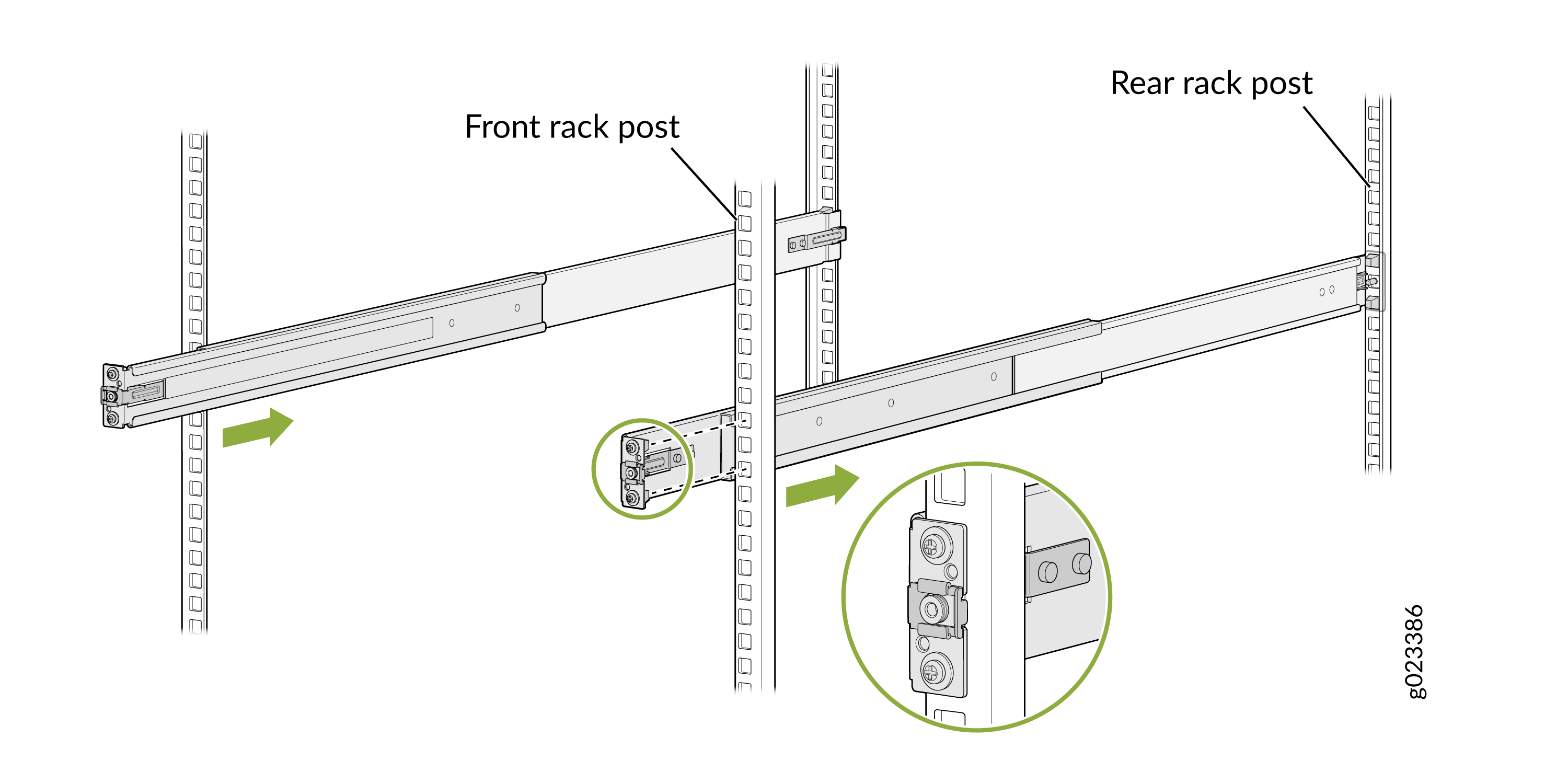
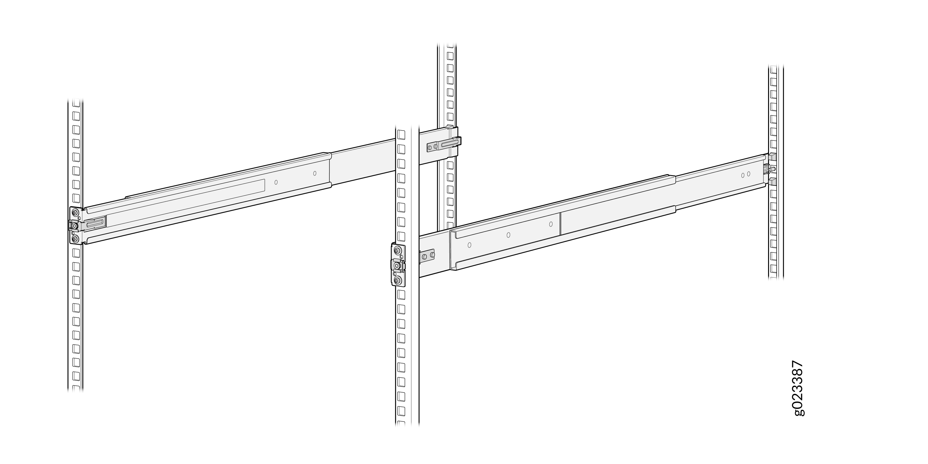
- Ensure that the front and rear latches on the mounting rails are locked in place.
Lift the device and position it in the rack, aligning the side-mounting brackets with the mounting rails. Slide the device into the channels of the mounting rails.
Figure 8: Position the switch in the rack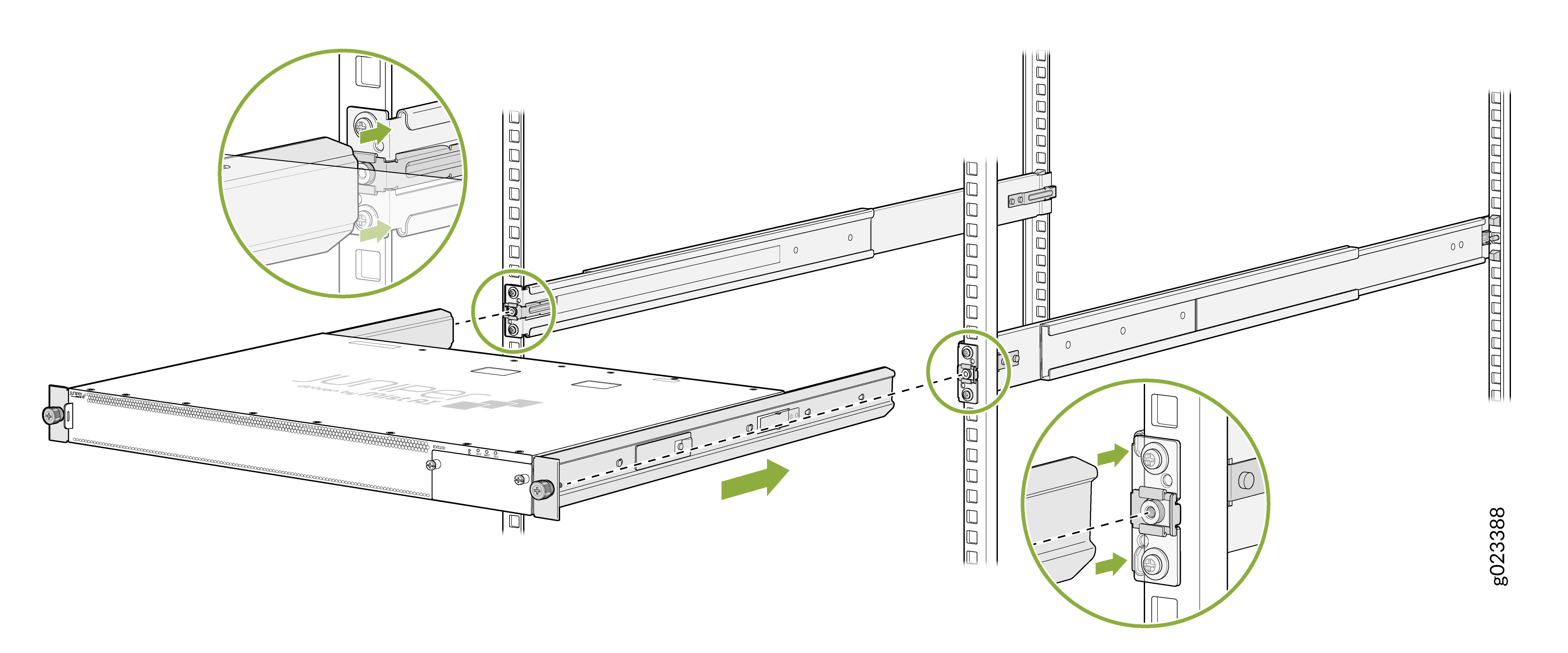
Tighten the two thumbscrews to secure the device
Figure 9: Secure the device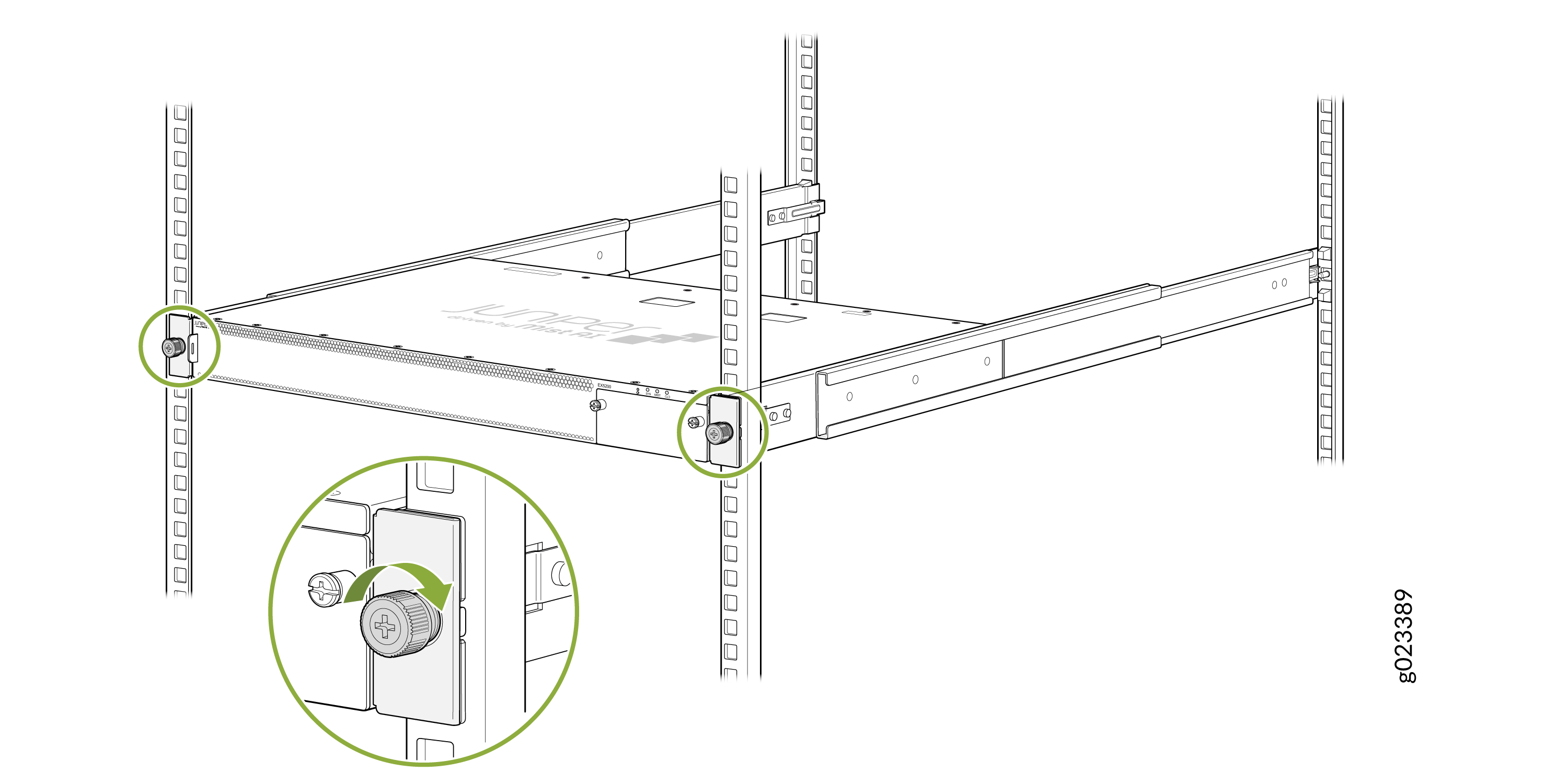
Mount an EX5200 Switch on a Wall
You can mount an EX5200 switch on a wall by using a separately orderable wall mount kit. (The remainder of this topic uses rack to mean rack or cabinet.)
Before mounting the switch on a wall:
-
Verify that the site meets the requirements described in Site Preparation Checklist for EX5200 Switches.
-
Place the rack in its permanent location, allowing adequate clearance for airflow and maintenance, and secure the rack to the building structure.
-
Read General Safety Guidelines , with particular attention to Chassis and Component Lifting Guidelines.
-
Ensure that you have taken the necessary precautions to prevent electrostatic discharge (ESD) damage (see Prevention of Electrostatic Discharge Damage).
-
Remove the switch from the shipping carton (see Unpack an EX5200 Switch).
Ensure that you have the following parts and tools available:
-
Number 2 Phillips (+) screwdriver—not provided
-
8-32 x 1.25 in. or M4 x 30 mm mounting screws— 4 (not provided)
-
Hollow wall anchors capable of supporting the combined weight of four fully loaded switches, up to 66 lb (30 kg) (not provided), if you are mounting the switch in sheetrock (wall board with a gypsum plaster core) or in wall board not backed by wall studs.
-
Wall mount brackets—2 (provided with the wall mount kit)
-
Wall mount bracket screws—12 (provided with the wall mount kit)
-
Covers for the empty extension module slot and the empty power supply slot—provided with the switch
-
An ESD grounding strap—not provided
For easier lifting, install any additional power supplies only after you mount the switch on the wall.
To mount the switch on the wall:
Place the switch on a flat, stable surface.
Wrap and fasten one end of the ESD wrist strap around your bare wrist, and connect the other end of the strap to a site ESD point.
Attach the wall mount brackets to the sides of the chassis by using four of the wall mount bracket screws on each side (see ). Use the screwdriver to tighten the screws.
Figure 10: Attach Wall Mount Brackets to the Switch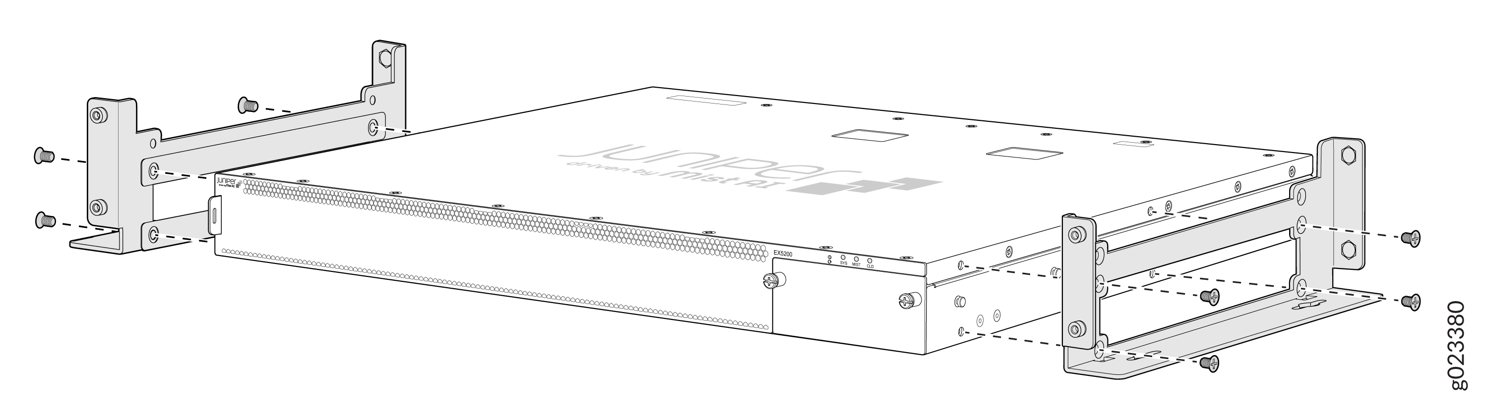
Insert the four mounting screws in the wall. Insert the top pair of mounting screws 15.2 cm apart, and insert the second pair of mounting screw 47.42 cm directly below the first pair.
Figure 11: Measurements for Mounting an EX5200 Switch on a Wall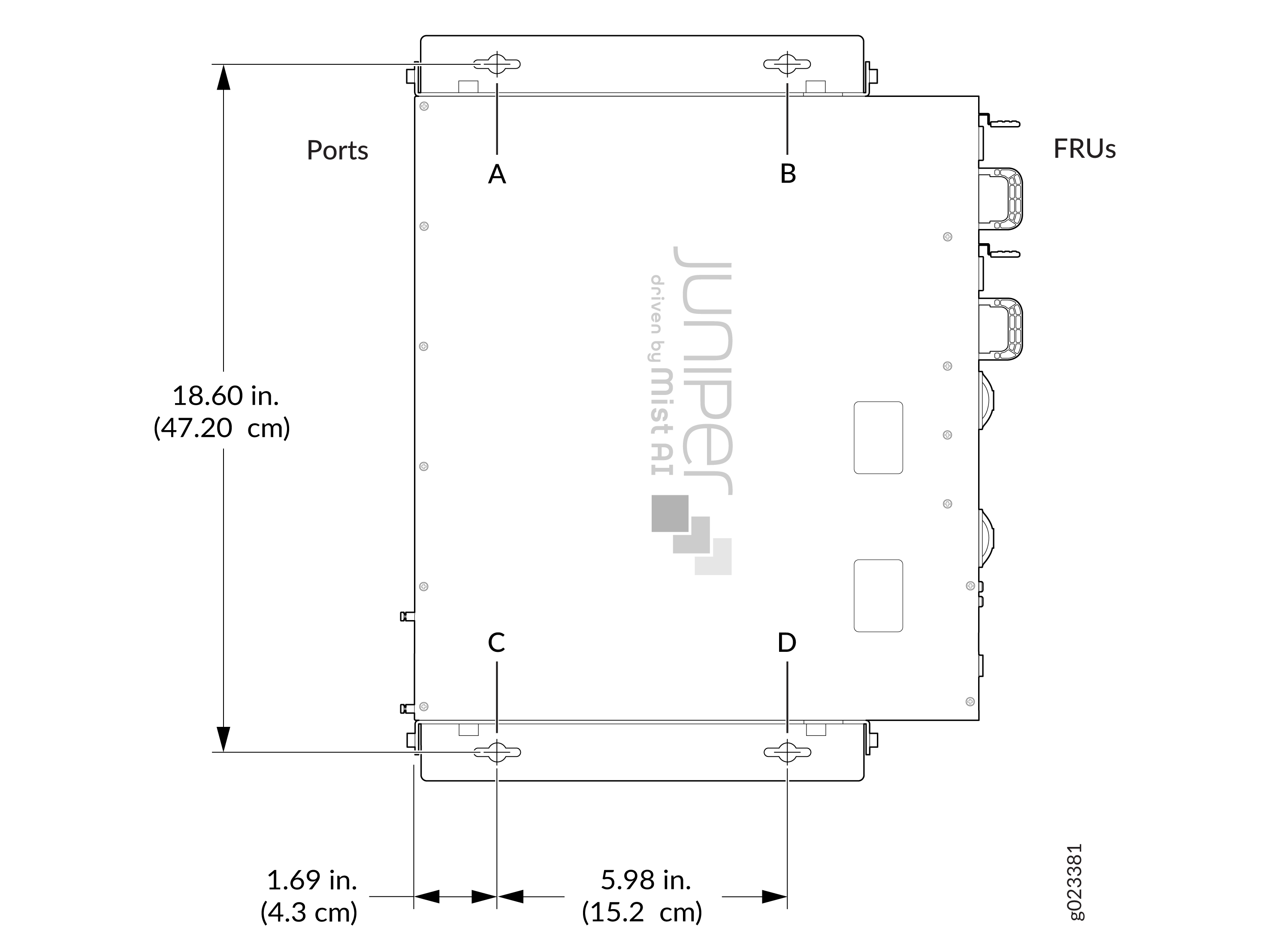
If the mounting screws are inserted in a wall board with no stud behind it, you must use dry wall anchors rated to support 66 lb (30 kg). Insert the screws into wall studs wherever possible to provide added support for the chassis.
Drive the screws only part way in, leaving about 1/4 in. (6 mm) distance between the head of the screw and the wall. Use the screwdriver to drive the screws in.
Grasp each side of the switch, lift the switch, and hang the brackets from the mounting screws (see ).
Figure 12: Mount the Switch on a Wall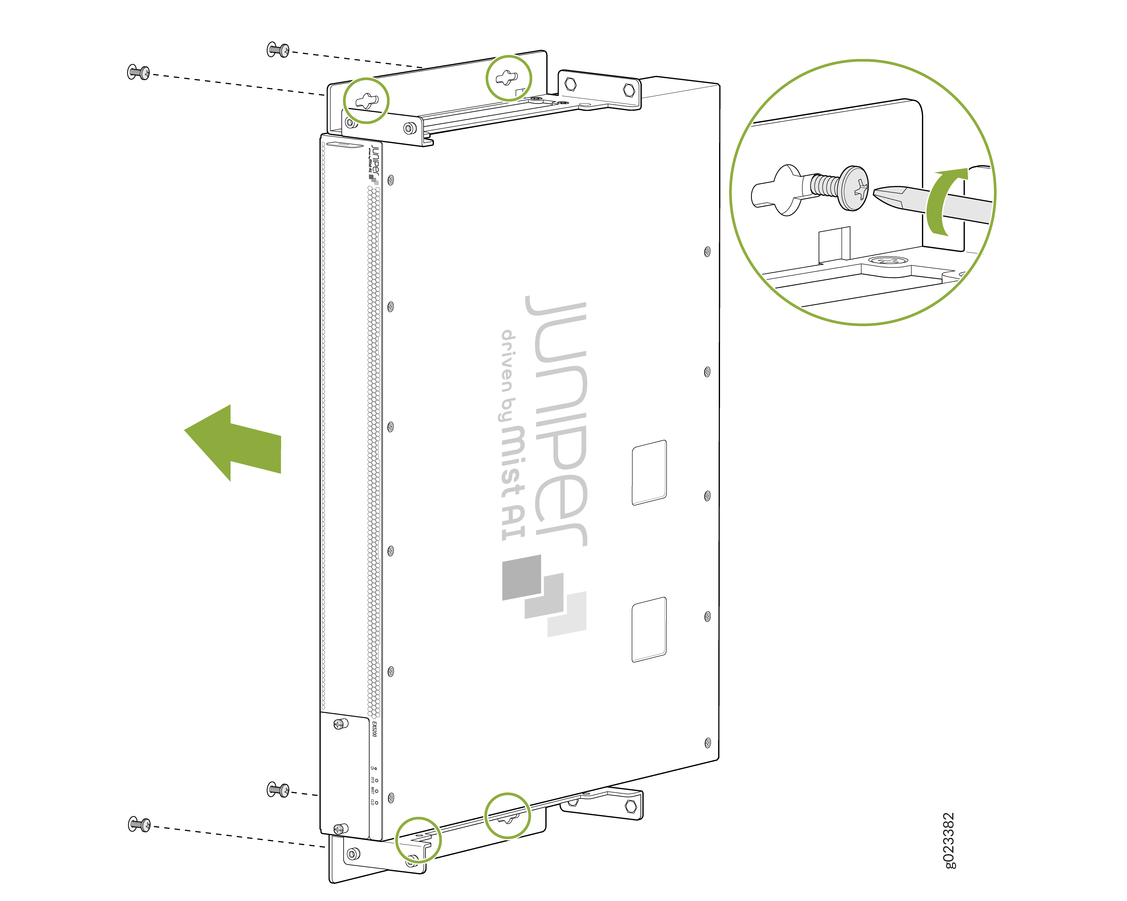
- Tighten the mounting screws by using the screwdriver.
- Cover the empty extension module slot and empty power supply slot by using the covers that came with the switch.
The slot covers reduce the risk of objects or substances entering the chassis. The covers also ensure optimal cooling for the switch.