EX5200 Chassis
Learn about the components in the EX5200 chassis.
The EX5200 chassis is a rigid sheet-metal structure that houses all components of the device.
EX5200 Chassis Specifications
|
Swith model |
Dimension (W x D x H) mm |
Dimension with fan tray and PSU install |
Full loaded weight (kg) with 2 PSU and new uplink blank |
Default weight (kg) With 1 PSU blank and new uplink blank |
Weight of spare (kg) |
|---|---|---|---|---|---|
|
EX5200-24MP |
439 x 399 x 43.6 mm |
439 x 437.86 x 43.6 mm |
8.06 |
7.36 |
6.22 |
|
EX5200-48MP |
439 x 399 x 43.6 mm |
439 x 437.86 x 43.6 mm |
8.56 |
7.78 |
6.43 |
|
EX5200-24T |
439 x 399 x 43.6 mm |
439 x 437.86 x 43.6 mm |
7.42 |
6.78 |
5.72 |
|
EX5200-48T |
439 x 399 x 43.6 mm |
439 x 437.86 x 43.6 mm |
7.6 |
7.02 |
5.98 |
|
FRU |
Dimension (W x D x H) mm |
Weight (kg) |
|---|---|---|
|
Fan tray |
40 x 111.35 x 40 mm |
0.14 |
|
PSU 2000 W |
83 x 128.9 x 40 mm |
0.86 to 0.926 |
|
PSU 1600 W |
83 x 128.9 x 40 mm |
0.915 |
|
PSU 550 W |
83 x 128.9 x 40 mm |
0.78 |
Environmental Specifications
You must install the switch in a rack or cabinet. You must house it in a dry, clean, well-ventilated, and temperature-controlled environment.
Follow these environmental guidelines:
-
Keep the site as dust-free as possible, because dust can clog air intake vents and filters, reducing the efficiency of the switch cooling system.
-
Maintain ambient airflow for normal switch operation. If the airflow is blocked or restricted, or if the intake air is too warm, the switch might overheat, leading to the switch temperature monitor shutting down the device to protect the hardware components.
The following table provides the required environmental conditions for normal switch operation of EX5200.
|
Environmental Guideline |
Description |
|---|---|
|
Altitude |
6000 feet at 40° C |
|
Operating Temperature |
0° to 45° C at sea level |
|
Storage Temperature |
-40° to 158° F, -40° to 70° C |
|
Relative Humidity |
(Operating) 5 to 90% non-condensing |
General Site Guidelines
Efficient device operation requires proper site planning. For the device to operate properly, you must ensure maintenance and proper layout of the equipment, rack or cabinet, and wiring closet.
To plan and create an acceptable operating environment for your device and prevent environmentally caused equipment failures:
-
Keep the area around the chassis free from dust and conductive material, such as metal flakes.
-
Follow the prescribed airflow guidelines to ensure that the cooling system functions properly. Ensure that the exhaust from other equipment does not blow into the intake vents of the device.
-
Follow the prescribed electrostatic discharge (ESD) prevention procedures to prevent damaging the equipment. Static discharge can cause components to fail completely or intermittently over time.
-
Install the device in a secure area, so that only authorized personnel can access the device.
Site Electrical Wiring Guidelines
describes the factors you must consider while planning the electrical wiring at your site.
You must provide a properly grounded and shielded environment and use electrical surge-suppression devices.
Avertissement Vous devez établir un environnement protégé et convenablement mis à la terre et utiliser des dispositifs de parasurtension.
|
Site Wiring Factor |
Guidelines |
|---|---|
|
Signaling limitations |
If your site experiences any of the following problems, consult experts in electrical surge suppression and shielding:
|
|
Radio frequency interference |
To reduce or eliminate RFI from your site wiring, do the following:
|
|
Electromagnetic compatibility |
If your site is susceptible to problems with electromagnetic compatibility (EMC), particularly from lightning or radio transmitters, seek expert advice. Strong sources of electromagnetic interference (EMI) can cause:
|
Rack Requirements
You can mount the device on two-post racks or four-post racks.
|
Rack Requirement |
Guidelines |
|---|---|
|
Rack Type |
A U is the standard rack unit defined by the Electronic Components Industry Association (ECIA) (http://www.ecianow.org). You can mount the device on a rack that provides bracket holes or hole patterns spaced at 1U (1.75 in. or 4.45 cm) increments and meets the size and strength requirements to support the weight. |
|
Mounting bracket hole spacing |
The holes in the mounting brackets are spaced at 1U (1.75 in. or 4.45 cm) so that the device can be mounted in any rack that provides holes spaced at that distance. |
|
Rack size and strength |
Ensure that the:
|
|
Rack connection to building structure |
|
Cabinet Requirements
You can mount the device in a cabinet that contains a 19-in. rack.
|
Cabinet Requirements |
Guidelines |
|---|---|
|
Cabinet size and clearance |
|
|
Cabinet airflow requirements |
When you mount the device in a cabinet:
|
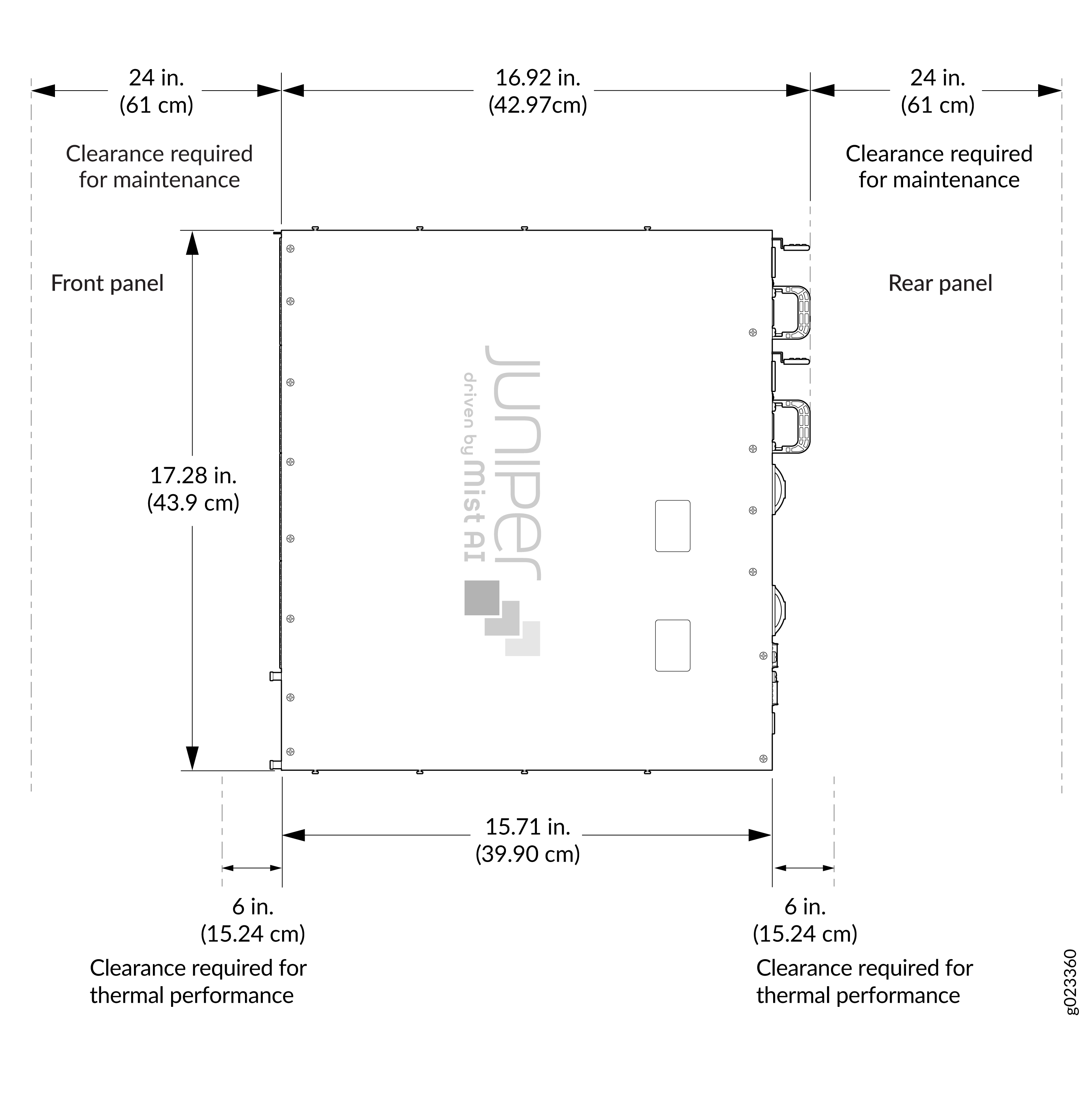
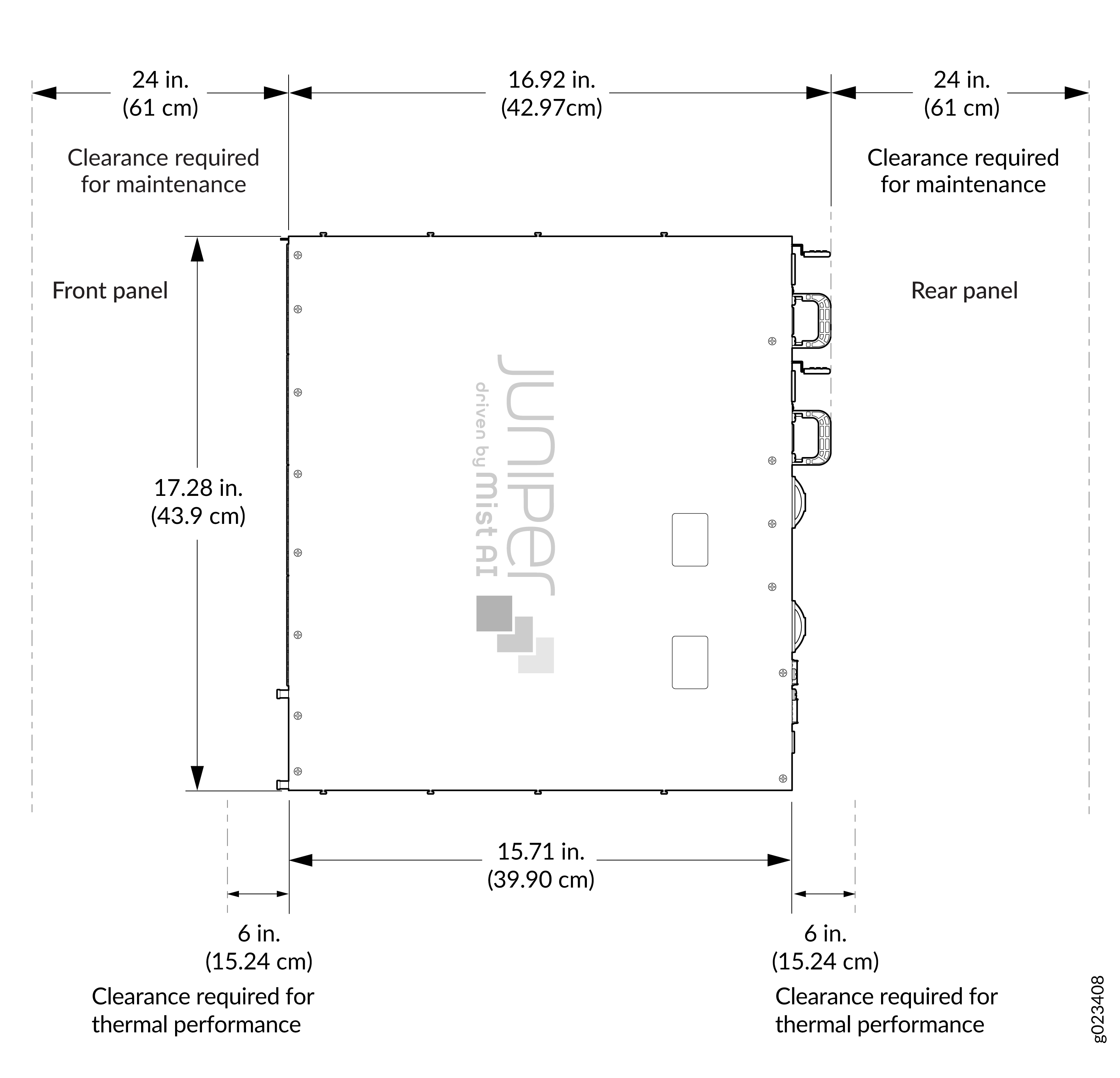
Clearance Requirements for Hardware Maintenance for EX5200 Switches
When planning the site for installing an EX5200 switch, follow these clearance requirements
-
For the cooling system to function properly, ensure that the airflow around the chassis is unrestricted.
-
If you are mounting the switch on a rack or cabinet along with other equipment, ensure that the hot air exhaust from other equipment does not blow into the cold air intake vents of the chassis.
-
Clearance requirements for thermal performance:
Leave at least 6 in. (15.2 cm) clearance in front of and behind the chassis for airflow.
-
Clearance requirements for hardware maintenance:
Leave at least 24 in. (61 cm) clearance in front of and behind the switch for service personnel to remove and install hardware components.