Create External System (Freeform)

Systems represent switches, routers, Linux hosts and so on. Unmanaged devices that you add to a blueprint are called external systems. They link to managed (internal) systems. You can create systems from scratch, or you can clone systems and customize them to create new ones. You can create (and clone) from the Topology view or from the Systems view.

Create External System (from Topology)

  1. From the blueprint, navigate to Staged > Physical > Topology and click Edit. (Images in this section are from HPE Networking Apstra Data Center Director version 4.1.1.)
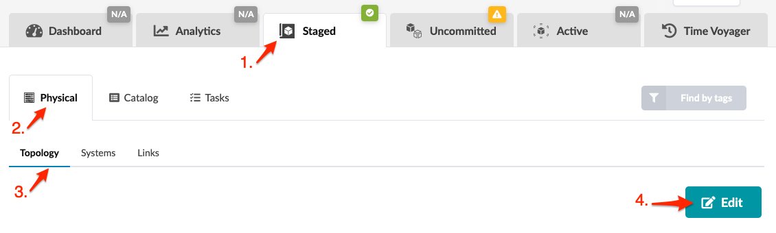
    User interface screenshot showing the Staged tab and Physical view with Topology subsection selected. Edit button available.
    CAUTION:

    Be careful. If you click away from the topology editor without clicking Save, your changes are discarded.

  2. In the topology editor click the Create external system button. The system appears as a rectangle with a system-generated name. You can move systems around on the canvas and when you save your changes in the editor and then reopen it, your systems will still be where you moved them to. You can save the system as is since there are no other required fields, or you can open the parameters dialog and configure optional fields.
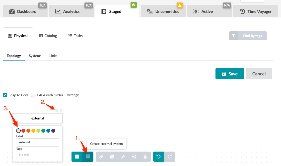
    User interface screenshot of a network topology design tool in physical view. Toolbar includes tabs like Dashboard, Analytics, and Time Voyager. Grid workspace allows arranging elements with Snap to Grid enabled. External system labeled external is created with options to edit label, color, and tags. Save and Cancel buttons are on the right.
  3. Click the gear to open the parameters dialog.
  4. You can change the system color that displays in the topology. This is useful for designating different roles or anything else you'd like to visually differentiate.
  5. You can change the system label to customize it to your environment.
  6. You can add tags, then later when you want to find systems you can use the Find by Tags feature (upper-right) to find them.
  7. Click Save to stage your new system and return to the Topology view. (If you leave the page without saving, your changes are discarded.)

Next Steps:

Continue to create external systems and internal systems until you've added your devices to the topology. Then you can create links for them.

Create External System (from Systems)

  1. From the blueprint, navigate to Staged > Physical > Systems and click Create System. (The image below is from Apstra DC Director version 4.1.1.)
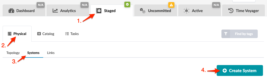
    User interface screenshot showing "Staged" tab highlighted with arrow, "Physical" selected in left navigation, "Systems" selected in sub-navigation, and teal "Create System" button highlighted. Red arrows label key areas.
  2. Enter a name and select EXTERNAL.
  3. Enter a hostname (optional) and tags (optional). If you add tags, then later when you want to find systems you can use the Find by Tags feature (upper-right) to find them.
  4. Click Create to stage the change and return to the Systems view. The newly created system appears in the list.

Next Steps:

Continue to create external systems and internal systems until you've added your devices. Then you can create links for them.

Clone External System (from Topology)

You can clone systems and customize them to create new ones from the Topology view.
  1. From the blueprint, navigate to Staged > Physical > Topology and click Edit.
  2. In the topology editor, select one or more existing external systems, then click the Clone selected nodes button. (The image below is from Apstra DC Director version 4.1.2.)
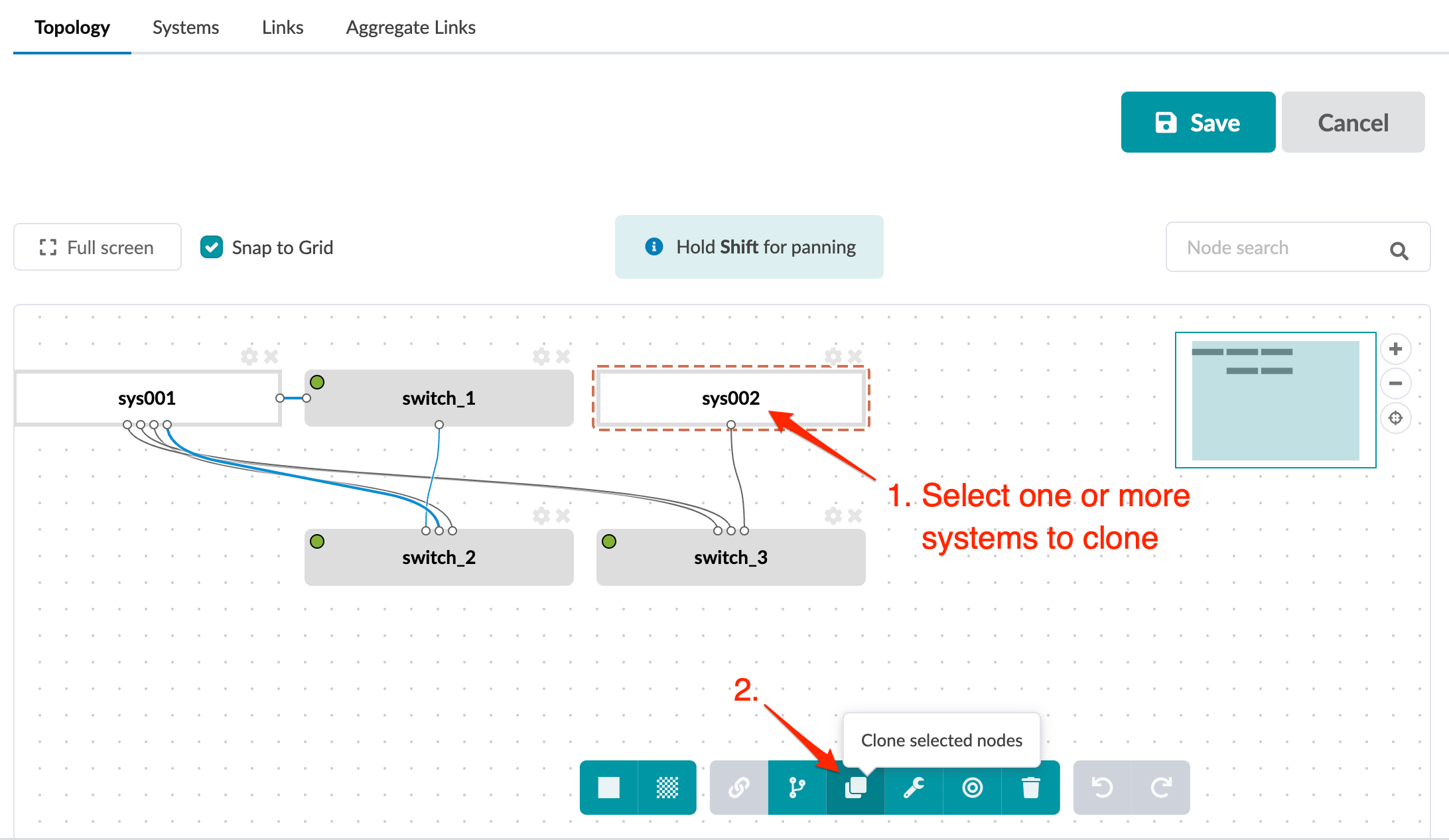
    Graphical user interface for managing network topology with nodes and connections. sys002 is selected. Instructions: select systems to clone, then use Clone selected nodes button. Toolbar includes actions like cloning and deleting. Navigation options available.
  3. The new system(s) appear as gray rectangles with system-generated names. You can move systems around on the canvas and when you save your changes in the editor and then reopen it, your systems will still be where you moved them to.
  4. Click the gear to open the parameters dialog, and change details to customize your new system.
  5. Click Save to stage your new system(s) and return to the Topology view. (If you leave the page without saving, your changes are discarded.)

Clone External System (from Systems)

You can clone systems and customize them to create new ones from the Systems view, as of Apstra DC Director version 4.1.2.
  1. From the blueprint, navigate to Staged > Physical > Systems and click Clone System for the system you want to clone.
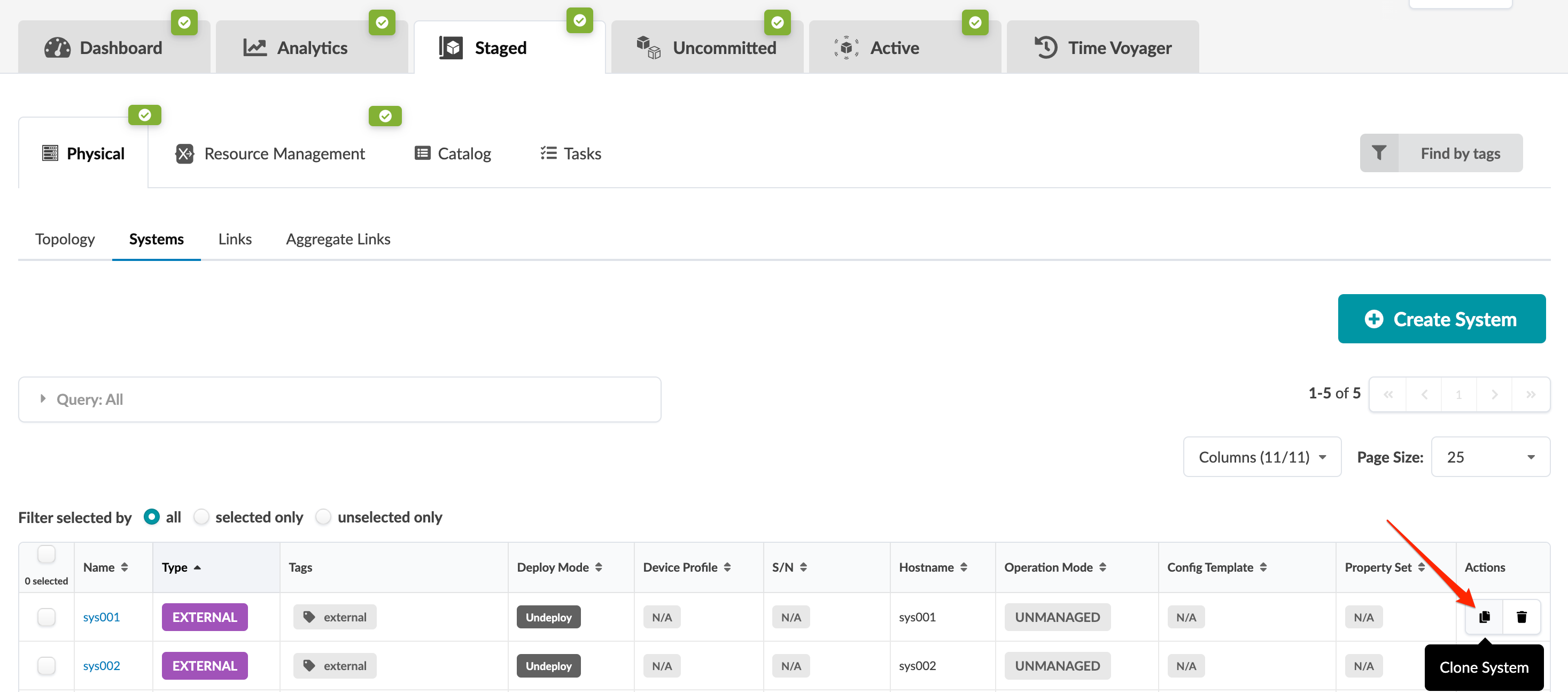
    User interface of a system management tool with tabs like Dashboard and Analytics, a systems table with columns like Name and Type, and a highlighted Clone System button.
  2. Change details to customize your new system.
  3. Click Clone to stage your new system and return to the Systems view.