Create AI Cluster Template
You can create blueprint templates based on L3 Clos AI fabrics or Rail-Collapsed AI fabrics using the GUI.
In an AI data center template, we organize the data center by rails, stripes, and spine elements. AI Clusters are supported on Juniper Networks devices only. This is due to the many variables and changing nature of AI fabrics, and the complexity of supporting advanced protocols (such as DCQCN).
To create an AI Cluster template using the GUI:
-
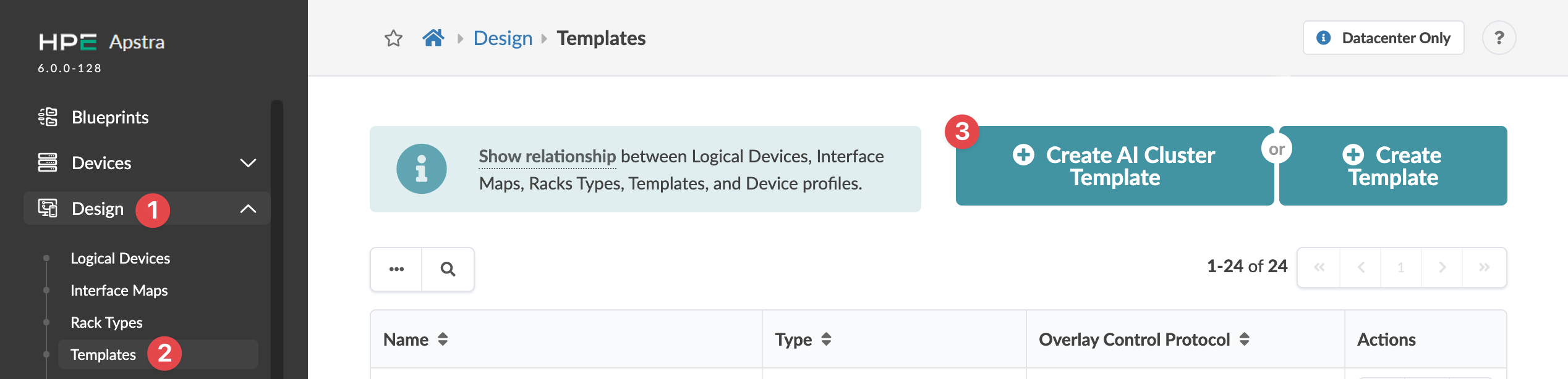
From the left navigation menu of the GUI, navigate to Design >
Templates and click Create AI Cluster Template.
 The Create AI Cluster Template dialog opens.
 -
Enter specifications (described below) for your design.
Note: After configuring your template you'll see a detailed preview. If you want to change any aspect of it, you can always return to this parameters page and change any details.
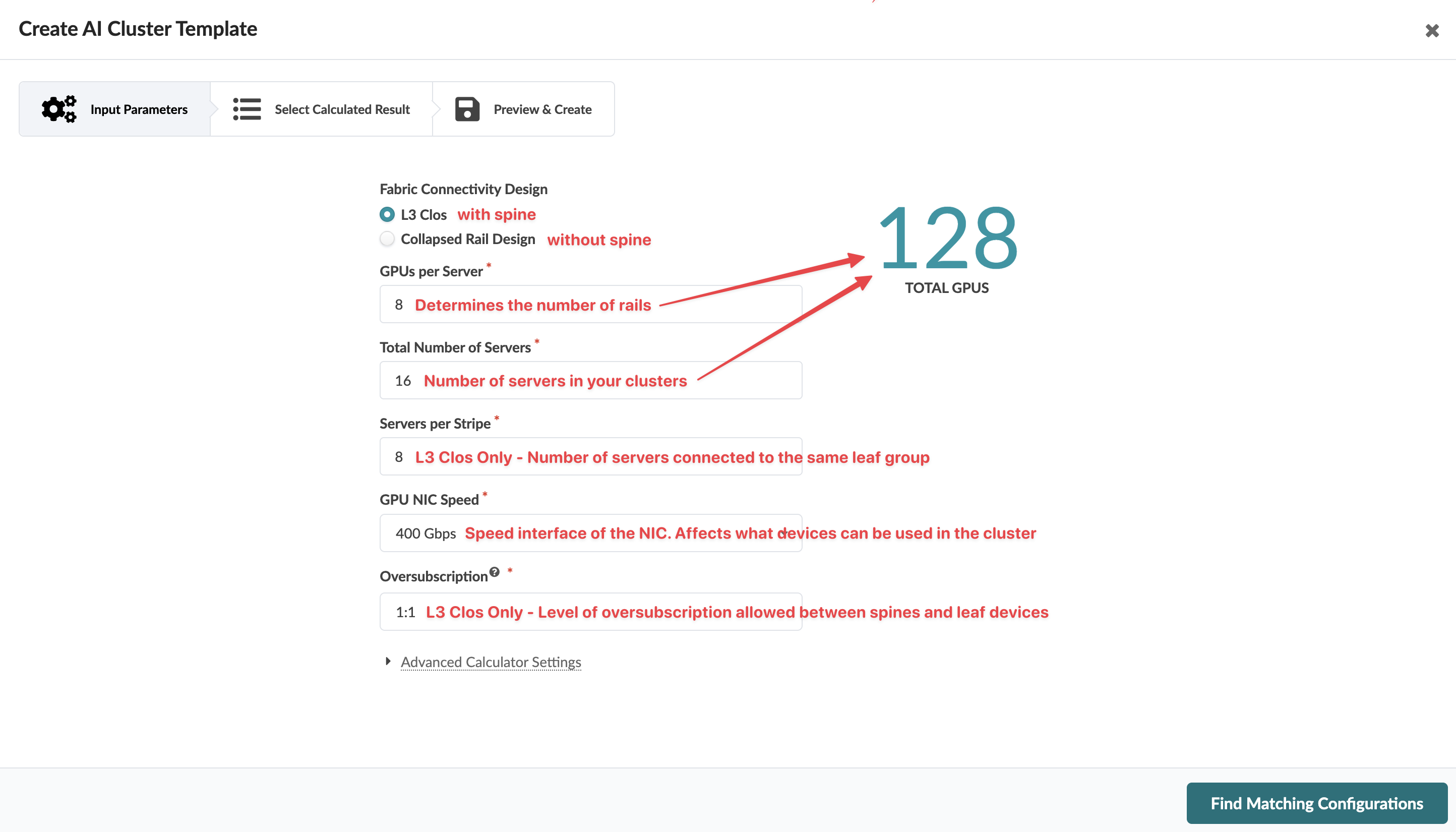
Table 1: AI Cluster Template Parameters Parameter
Description
Fabric Connectivity Design
Depends on size of design:
-
L3 Clos (with spine) - for larger designs that justify having a spine
-
Collapsed Rail Design (no spine) - for most small AI cluster designs
GPUs per Server
All GPU servers must have the same number of GPUs. Changing the number of GPUs per server automatically changes the total number of GPUs (the big number on the right).
If you need to design with a different number of GPUs per server, consider creating the design with the rack type builder.
Total Number of Servers
Enter the total number of servers to include. Changing the number of servers automatically changes the total number of GPUs (the big number on the right).
Servers per Stripe (L3 Clos Only)
Enter the number of servers to include for each stripe.
GPU NIC Speed (L3 Clos Only)
Enter the speed of the NIC. Speed affects what devices can be used in the cluster.
Oversubsription (L3 Clos Only)
This is the target oversubscription allowed between the spine and the leaf layer of the design. It's calculated as a ratio of southbound bandwidth to northbound bandwidth measured on the leaf switches layer.
For example, a 2:1 oversubscription ratio with 8 GPUs per server means for each leaf in the design there would be 8 ports facing the server GPUs and 4 ports facing the spine layer.
-
-
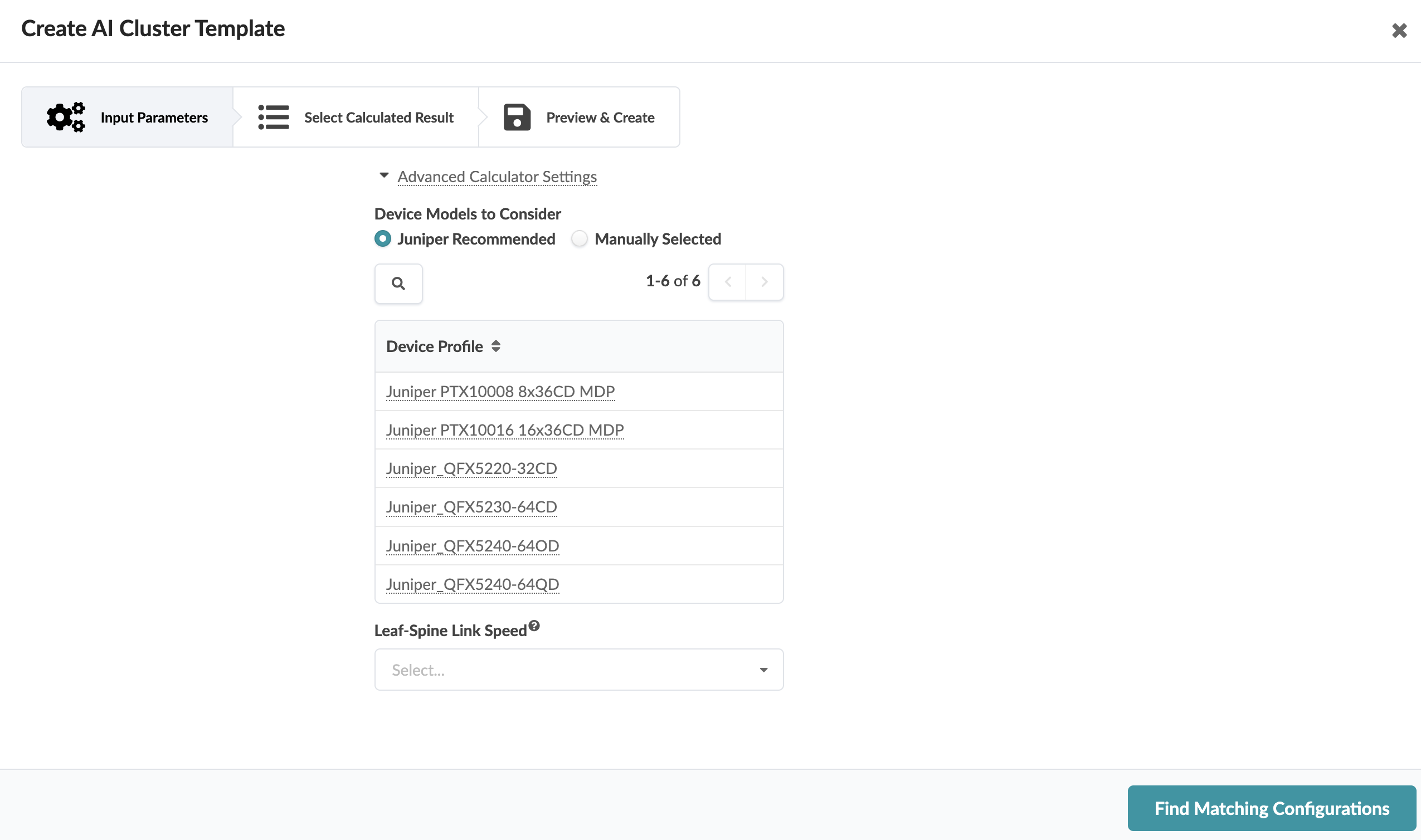
Configure advanced settings, as applicable.
-
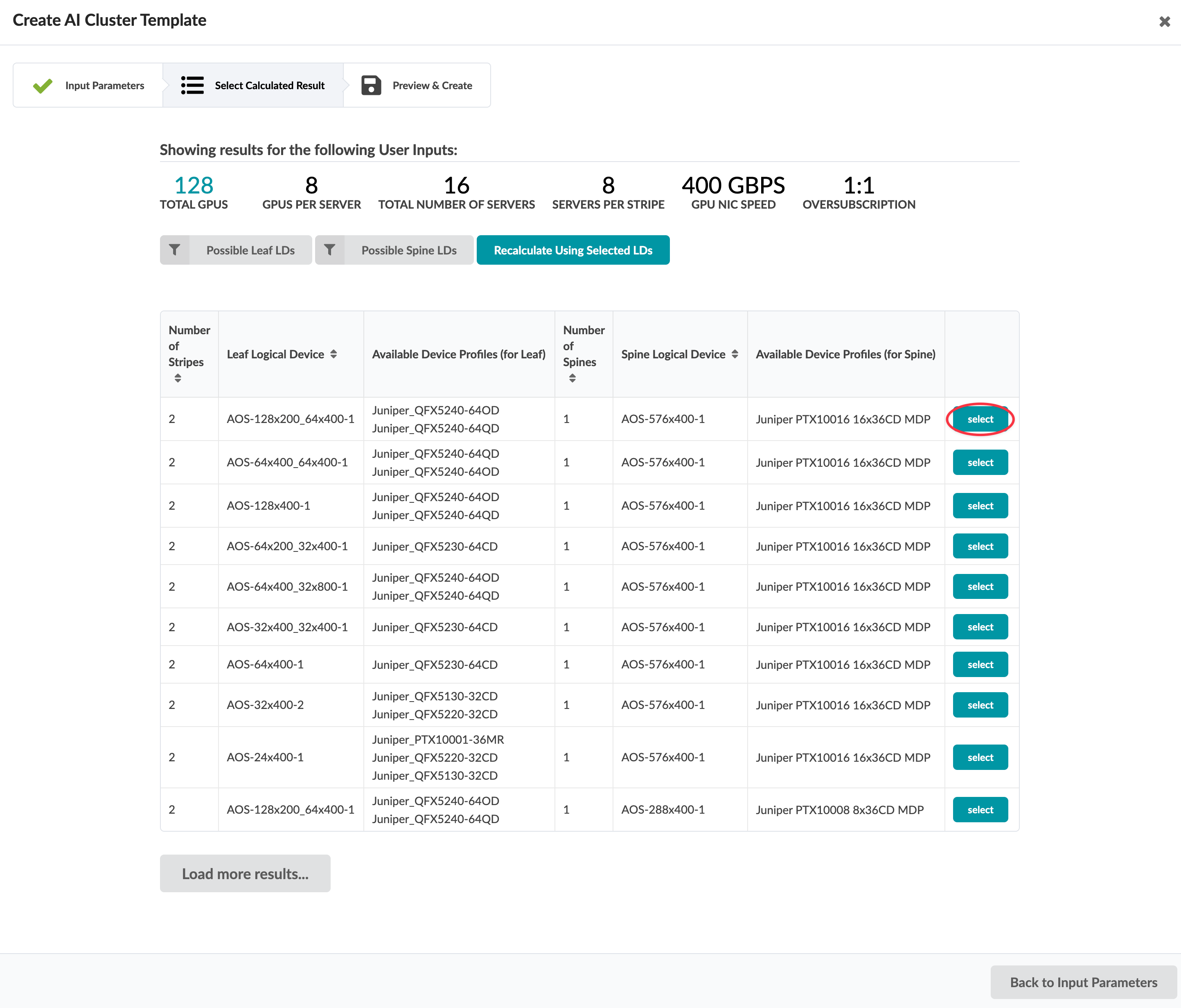
Select one of the options.
The tables often have many proposals. You can filter the results based on leaf and/or spine logical devices. For example, you may decide to select only leaf logical devices with 400G interfaces excluding those with 200G. Or, you may want to select spines that are fixed-form factors only while excluding those where the port count indicates chassis.
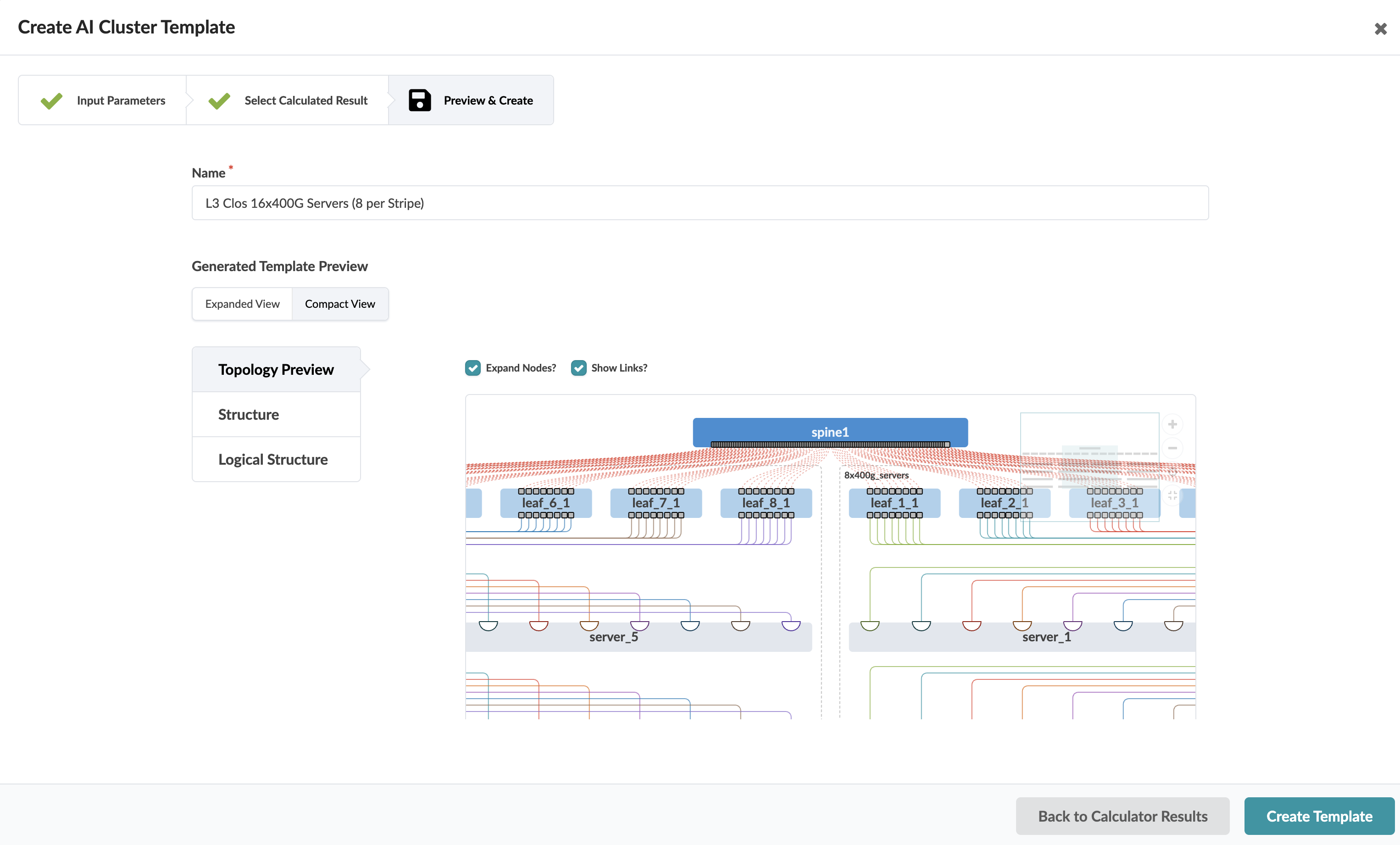
 The template preview opens for your review. This preview renders a topology of your AI cluster, and provides port and logical structure information. Hover over elements of the rendered topology for more information.
 -
Click Create Template (bottom-right).