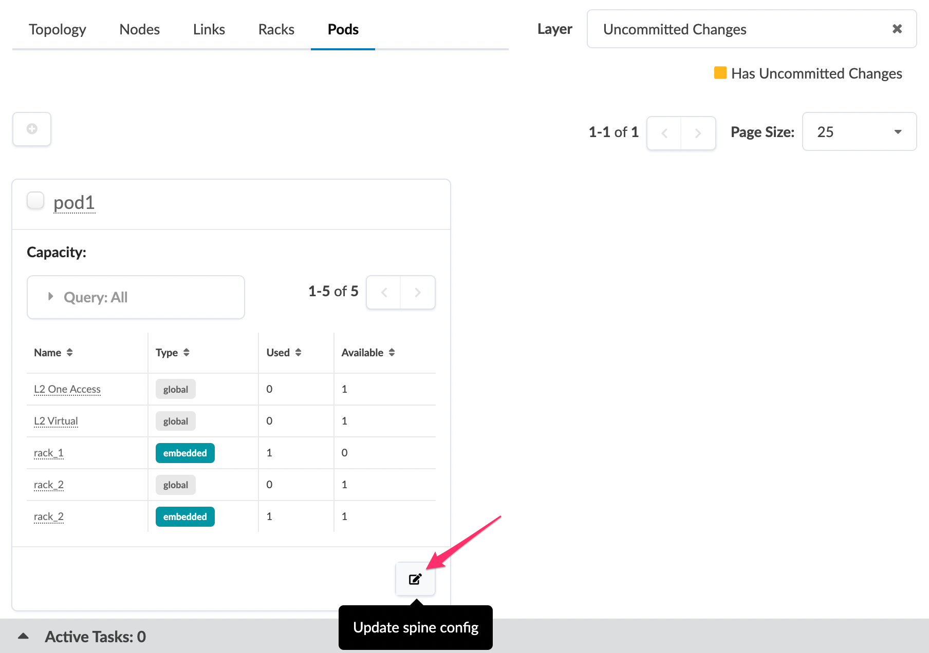
Change Spine Logical Device (Pod)

As a Day-2 operation, you can increase capabilities with a different spine logical device on both 3-stage and 5-stage blueprints. (On 5-stage topologies you can also change the superspine logical device.) Changes affect the entire pod, not just a node. Based on the change, this could be disruptive.

  1. From the blueprint, navigate to Staged > Physical > Pods to go to the Pods view.
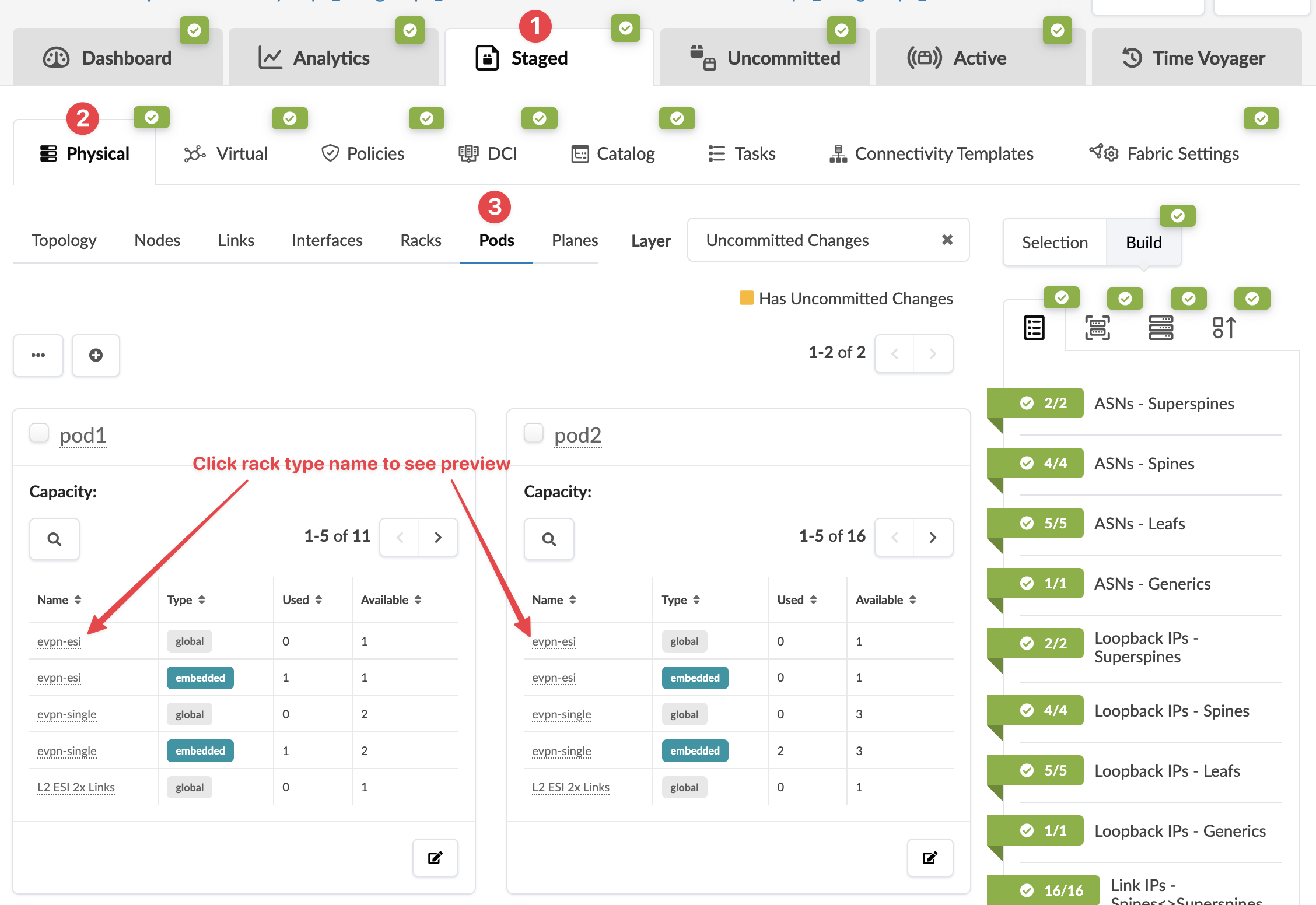
    Network management interface showing staged physical pods with configurations, rack types, uncommitted changes, and ASN and IP details for data center infrastructure.
  2. Click the Update spine config button on the bottom-right of the card for the pod to change.User interface screenshot of network configuration with "Pods" tab showing a table of pod details. Highlighted "Update spine config" button at bottom right.
    The Update Spine Config dialog opens.
  3. From the Spine Logical Device drop-down list, select a different logical device.
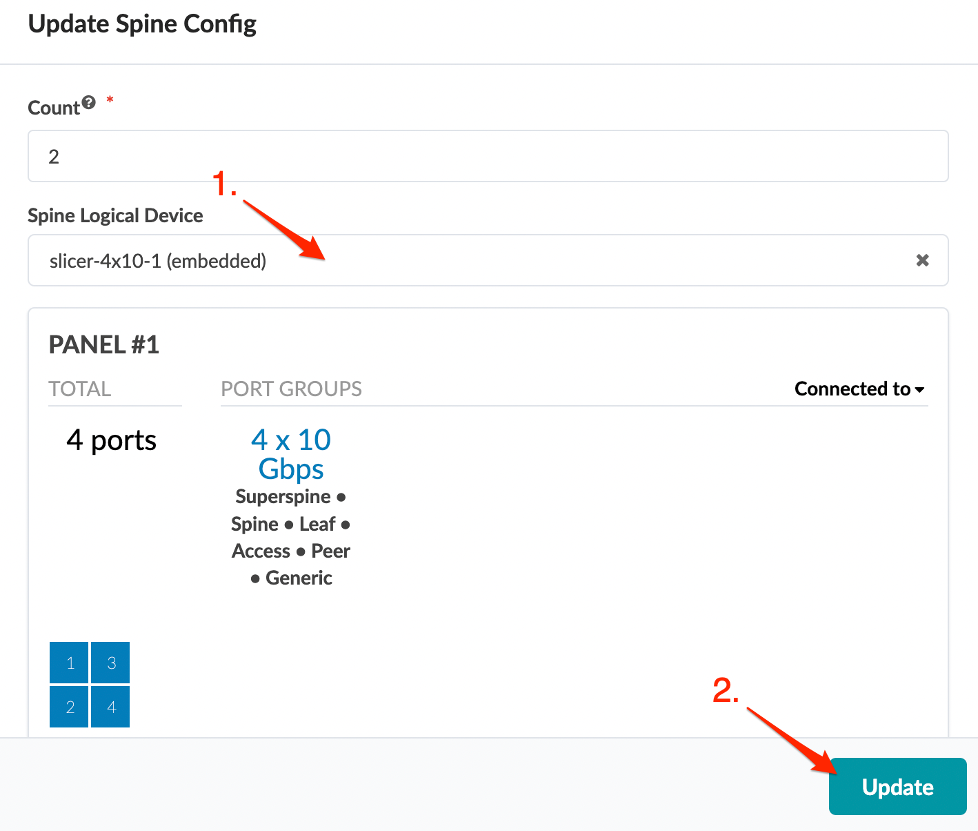
    Configuration interface for updating Spine Config. Count set to 2 devices. Using slicer-4x10⁻¹ embedded logical device. Panel 1 has 4 ports grouped as 4 x 10 Gbps. Ports categorized for Superspine, Spine, Leaf, Access, Peer, and Generic roles. Visual grid of 4 ports. Update button to apply changes. Red arrows highlight Spine Logical Device field and Update button.
  4. Click Update to stage your changes and return to the Pods view.
    Build errors appear because interface maps need to be assigned.
  5. Click the Device Profiles tab in the right panel and assign interface maps, as needed.