Replace Extension Modules on the EX5200 Switch
Maintaining the EX5200 switch includes removing and installing the extension modules.
Extension modules are hot-insertable field-replaceable units (FRUs). You can replace them without powering off the device or disrupting the device functions.
The supported extension modules are only hot-insertable and not hot-removable. To replace an extension module, the extension module should be taken offline first, the extension module removed, then replaced with the new extension module.
To take an extension module offline use this command: request chassis pic
offline fpc-slot <fpc-slot> pic-slot <pic-slot>
To bring an extension module online use this command: request chassis pic
online fpc-slot <fpc-slot> pic-slot <pic-slot>
The replacement process is the same for all extension modules supported on the EX5200 switch.
Before you remove or insert an extension module/uplink module, ensure that you have the following parts and tools:
-
An electrostatic discharge (ESD) grounding strap (not provided) - ensure that you have taken the necessary precautions to prevent electrostatic discharge (ESD) damage (see Prevention of Electrostatic Discharge Damage.
-
If there are any transceivers installed in the extension module, remove them before you remove the extension module or insert an extension module.
-
A replacement extension module or cover for the empty extension module slot
-
An antistatic bag or an antistatic mat—not provided
-
A replacement extension module
-
A blank cover panel (in case you're not replacing the extension module)
-
Number 2 Phillips (+) screwdriver—not provided
Remove any installed transceivers before replacing the extension module.
We recommend that you install either a replacement extension module or a cover over the empty module slot to reduce the risk of objects or substances entering the chassis and to ensure optimal cooling of the switch.
Extension modules are not part of the shipping configuration. If you want to purchase them, you must order them separately and register them (see Update Base Installation Data).
Remove an Extension Module from an EX5200 Switch
To remove an extension module:
Take the extension module offline by issuing the following CLI command
user@switch> request chassis pic offline fpc-slot slot-number pic-slot slot-number
Wrap and fasten one end of the ESD wrist strap around your bare wrist, and connect the other end of the strap to a site ESD point.
Note:If a grounding strap is not available, hold the extension module in its antistatic bag in one hand and touch the exposed, bare metal of the switch with the other hand to ground yourself and the component.
Loosen both captive screws on the faceplate of the extension module by using your fingers. If you are unable to unscrew the captive screws by using your fingers, use the screwdriver.
CAUTION:Do not pull the extension module out of the module slot by holding the faceplate of the extension module.
Hold both the ejector handles or the captive screws on the extension module and gently pull the extension module toward you and out of the module slot.
Figure 1: Remove an uplink module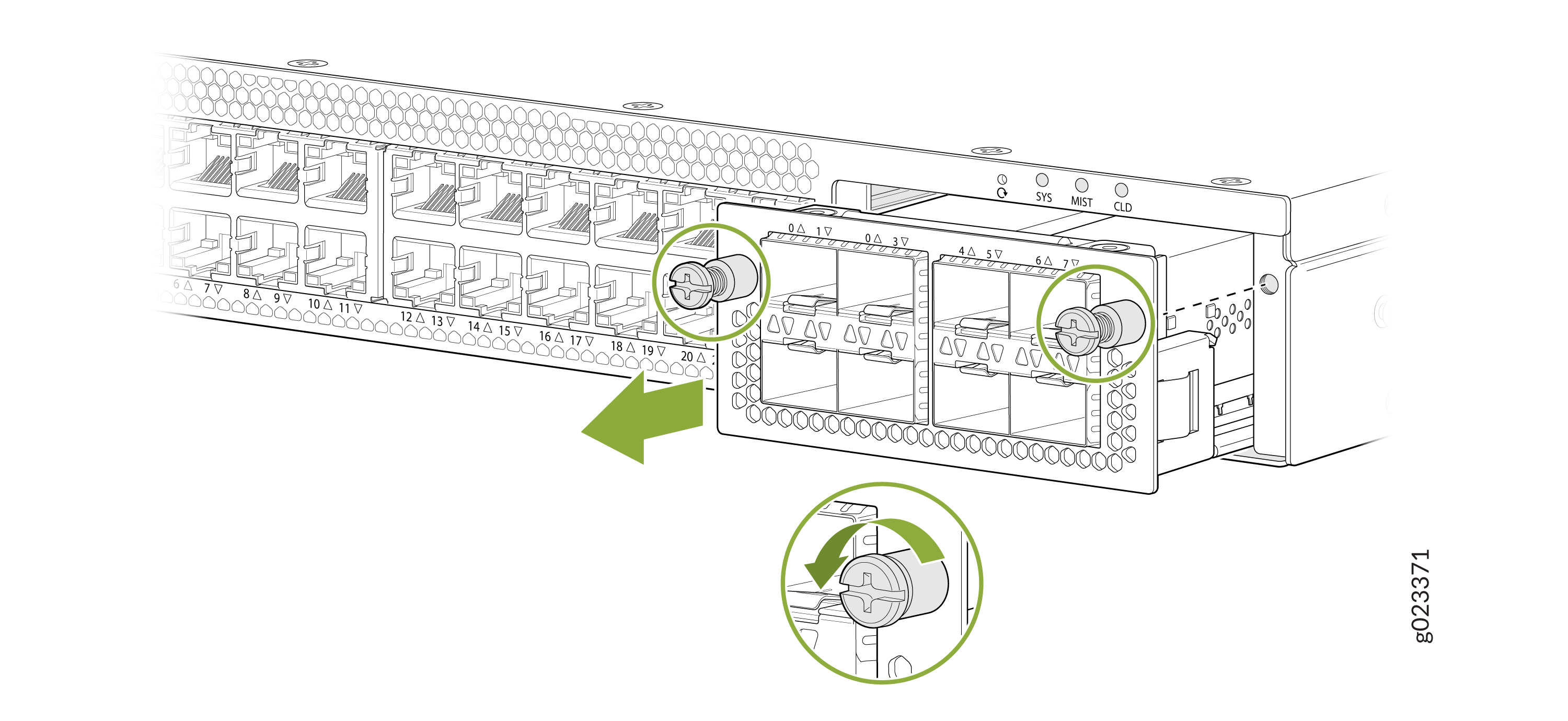
Place the extension module in an antistatic bag or on an antistatic mat placed on a flat, stable surface.
If you are not replacing the extension module, install the cover over the empty slot.
Note:After you have removed an extension module, wait for at least 10 seconds before you install an extension module. If you do not wait for at least 10 seconds, the interfaces on the extension module might not come up.
Install an Extension Module in an EX5200 Switch
To install an extension module:
- Wrap and fasten one end of the ESD wrist strap around your bare wrist, and
connect the other end of the strap to a site ESD point.Note:
If a grounding strap is not available, hold the extension module in its antistatic bag in one hand and touch the exposed, bare metal of the switch with the other hand to ground yourself and the component.
If the extension module slot has a cover on it, loosen both the screws on the cover by using your fingers. If you are unable to unscrew the screws by using your fingers, use the screwdriver. Hold both the screws and gently pull the cover outward, and save it for later use.
Note:If the extension module slot has a cover on it, loosen both the screws on the cover by using your fingers. If you are unable to unscrew the screws by using your fingers, use the screwdriver. Hold both the screws and gently pull the cover outward, and save it for later use.
Ensure not to touch module components, pins, leads, or solder connections, remove the extension module from its bag.
CAUTION:Before you slide the extension module into the slot on the switch chassis, ensure the extension module is aligned correctly. Misalignment might cause the pins to bend, making the extension module unusable.
Using both hands, place the module in the empty slot and slide it in gently until it is fully seated.
Tighten both the captive screws by using your fingers or the screwdriver
Figure 2: Install an Uplink Module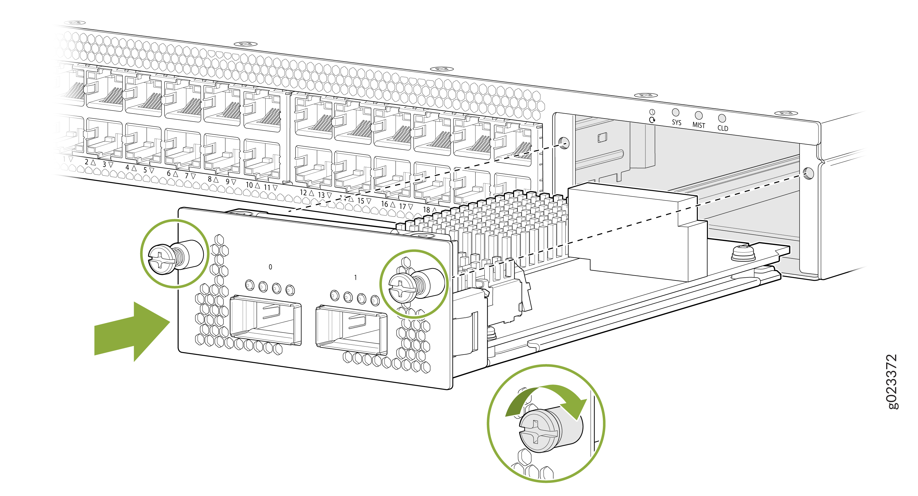
Bring the extension module online
request chassis pic
                    online fpc-slot <fpc-slot> pic-slot <pic-slot>