Connect the EX5200 Switch to Power
Connecting power to the EX5200 switch involves the following steps and safety precautions to prevent equipment damage and personal injury.
Connect Earth Ground to an EX5200 Switch
To ensure proper operation and to meet electromagnetic interference (EMI) requirements, you must connect the EX5200 switch to earth ground before you connect power to the switch. You must use the protective earthing terminal on the switch chassis to connect the switch to earth ground (see Figure 1).
You must install the EX5200 switch in a restricted-access location and ensure that the chassis is always properly grounded. EX5200 switches have a 2-hole protective grounding terminal on the rear panel of the chassis. Under all circumstances, use this grounding connection to ground the chassis. For AC-powered systems, you must also use the grounding wire in the AC power cord along with the two-hole grounding lug connection. This tested system meets or exceeds all applicable EMC regulatory requirements with the two-hole protective grounding terminal.
Ensure that a licensed electrician has attached the appropriate grounding lug to the grounding cable that you supply. Using a grounding cable with an incorrectly attached lug can damage the switch.
To ground the EX5200 system, you can use LCD10-10AF-L or equivalent, two-hole lug to ground the EX5200. Follow these guidelines:
-
14-10 AWG, minimum 90° C wire, or as permitted by the local code, with a Panduit LCD10-10AF-L or equivalent lug attached.
To ground the EX5200 switch:
-
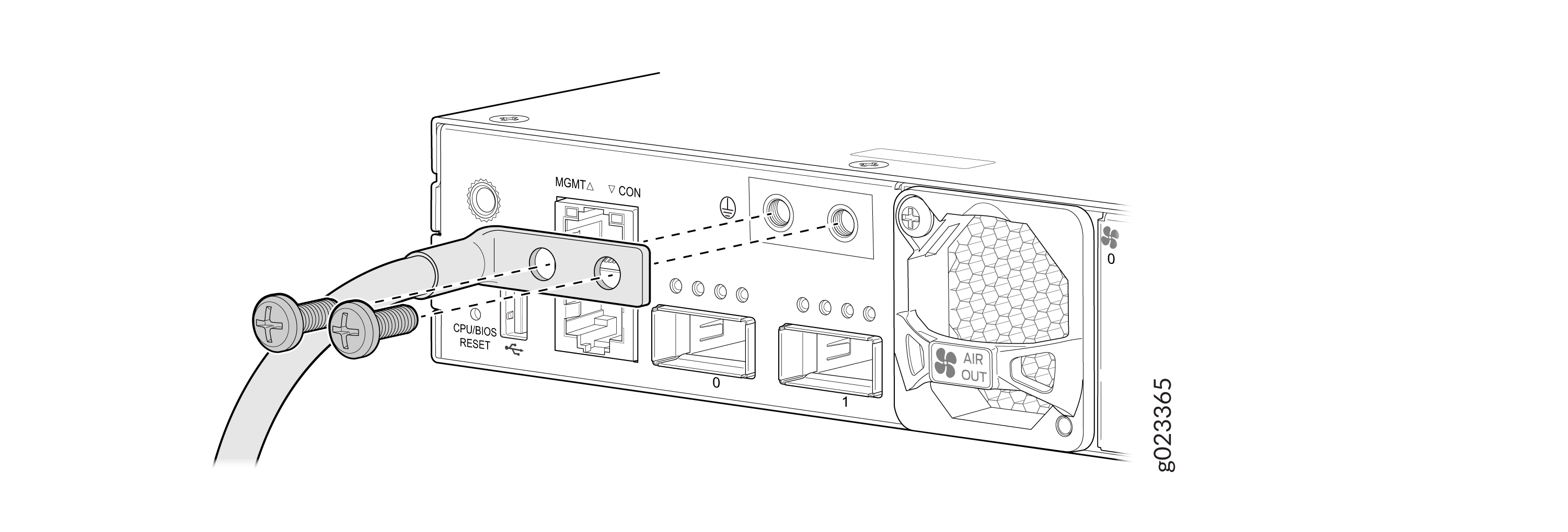
Place the grounding lug attached to the grounding cable over the protective
earthing terminal on the rear panel (see Figure 1).
Figure 1: Connect a Grounding Cable to the Switch
Connect AC Power to an EX5200 Switch
Before you connect AC power to the switch:
-
Ensure that you have a power cord appropriate for your geographical location available.
-
Ensure that you have the power cord retainer shipped with the switch.
-
Ensure that you have taken the necessary precautions to prevent electrostatic discharge (ESD) damage (see Prevention of Electrostatic Discharge Damage).
-
Ensure that you have an ESD grounding strap (not provided).
-
Ensure that you have connected the switch chassis to earth ground.
CAUTION:Before you connect power to the switch, a licensed electrician must attach a cable lug to the grounding cable that you supply. A cable with an incorrectly attached lug can damage the switch (for example, by causing a short circuit).
To meet electromagnetic interference (EMI) requirements and to ensure proper operation, you must connect the chassis to earth ground before you connect it to power (see Connect Earth Ground to an EX5200 Switch).
-
Ensure that you provide an external certified circuit breaker (2-pole circuit breaker based on your device current rating) rated minimum 13 A, 16 A, or 20 A in the building installation or as per local electrical code.
We ship the EX5200 switches with one power supply preinstalled on the rear panel. Each power supply is a hot-removable and hot-insertable field-replaceable unit (FRU) when the second power supply is installed and running: You can remove and replace either one of them without powering off the switch or disrupting switch functions.
To connect power to an EX5200 switch with an AC power supply:
-
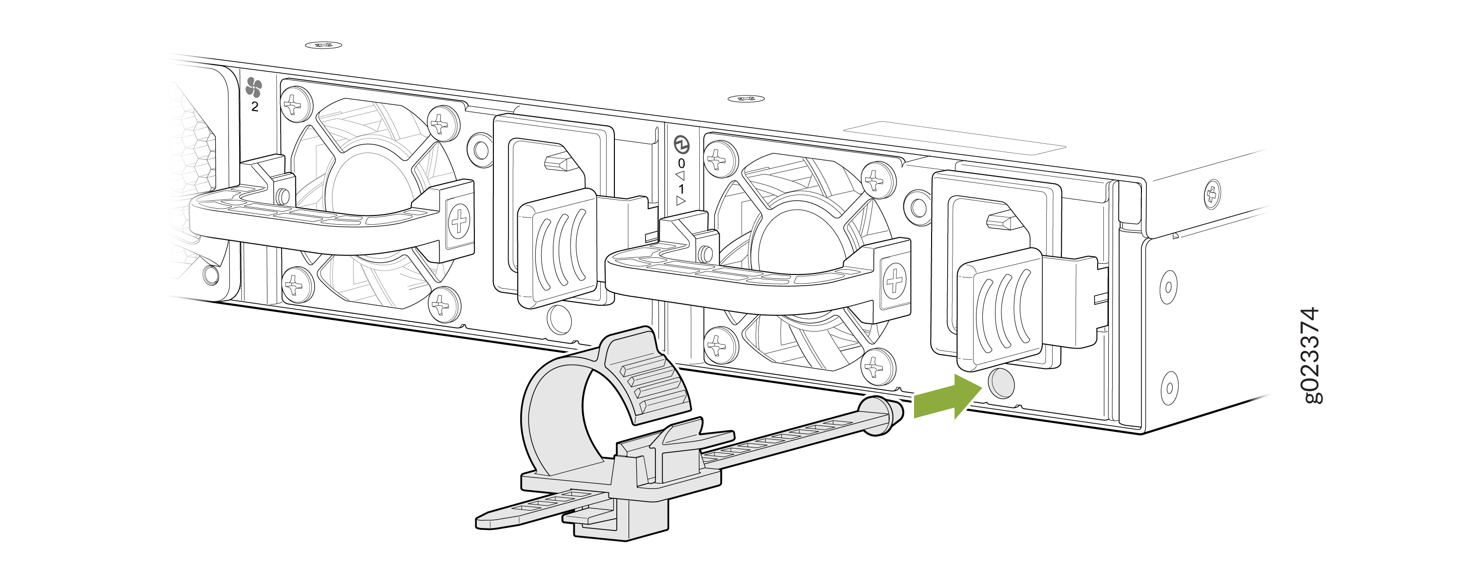
Push the end of the retainer strip into the hole below the inlet on the
power supply faceplate until it snaps into place. Ensure that the loop in
the retainer strip points upward (see Figure 2).
Figure 2: Connect Retainer Strip
-
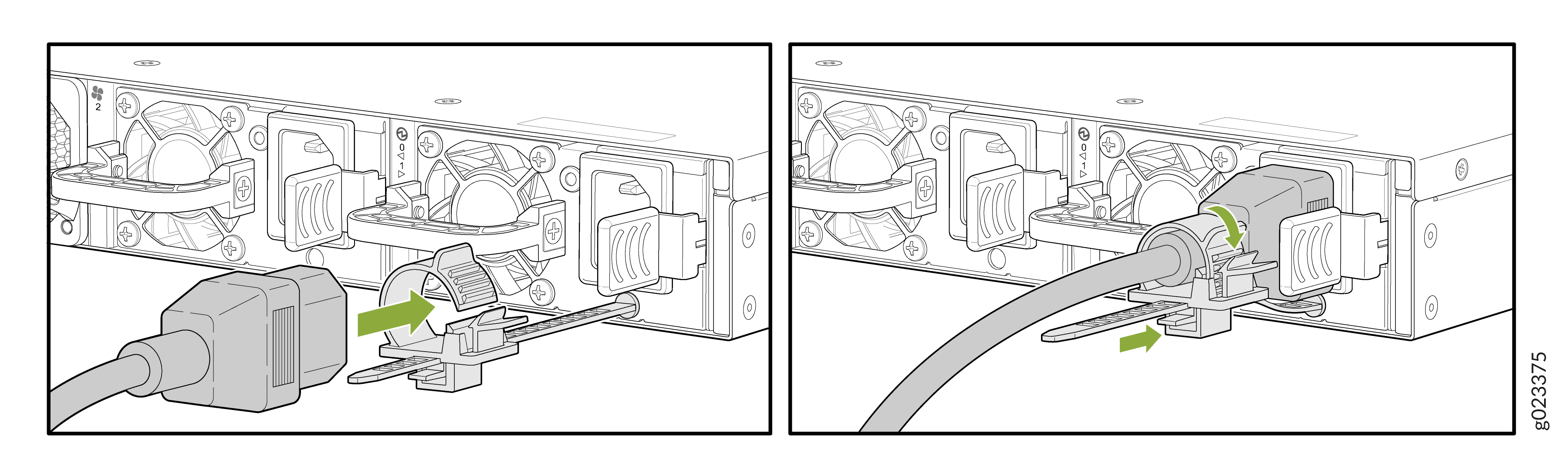
Press the tab on the loop and draw out the loop into a tight circle (see
Figure 3).
Figure 3: Connect Power to an EX5200 Switch with an AC Power Supply