EX5200 Chassis LEDs
This topic describes the status LEDs for the chassis and ports on the EX5200 switch..
The LEDs on the EX5200 switch indicate the status of the device and its components. You can also use the LEDs for troubleshooting.
Chassis Status LEDs
The EX5200 has three chassis status LEDS - SYS, MST, and CLD. SYS (System): indicates the software loading and general operating status of the Junos OS. It also indicates the alarm conditions on the chassis. MST (Master): defines the role of a unit inside a Virtual Chassis configuration. CLD (Cloud-Ready): Displays the connection and management status with cloud services like Juniper Mist
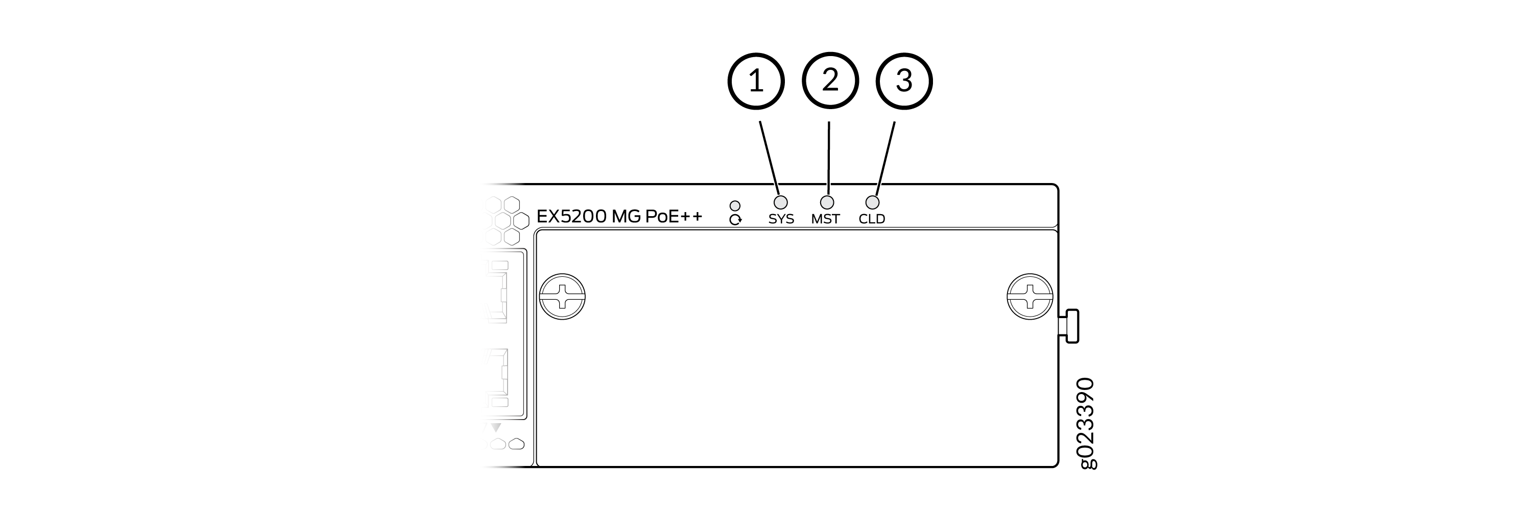
Table 1 describes the system chassis status LED labeled as SYS on an EX5200 switch when in standalone mode.
Table 2 describes the system chassis status LED labeled as SYS on an EX5200 switch when in Virtual Chassis mode.
|
Callout |
LED Label |
Color |
State and Description |
|---|---|---|---|
|
1 |
SYS |
Blinking green |
Switch is booting up. |
|
Solid green |
Switch has booted up. No alarms. |
||
|
Amber |
Minor alarm |
||
|
Red |
Major alarm |
||
|
Blue |
Appears on short press of front panel reset button. See Reset Button Functionality. |
||
|
Purple |
Appears on long press of front panel reset button. See Reset Button Functionality |
|
Callout |
LED Label |
Virtual Chassis Member and LED Color |
State and Description |
||
|---|---|---|---|---|---|
|
Master |
Backup |
Linecard |
|||
|
1 |
SYS |
Green |
Green |
Green |
No alarms |
|
Amber or Red |
Green |
Green |
Alarm present on master member |
||
|
Green |
Amber or Red |
Green |
alarm present on backup member |
||
|
Green |
Green |
Amber or Red |
Alarm present on linecard member |
||
Table 3 describes the chassis status LED labeled MST when the EX5200 switch is in standalone mode.
Table 4 describes the chassis status LED labeled MST when the EX5200 switch is in virtual chassis mode.
|
Callout |
LED Label |
Color |
State and Description |
|---|---|---|---|
|
2 |
MST |
Green |
In a standalone switch:
|
|
Callout |
LED Label |
Virtual Chassis Member |
Color |
State and Description |
|---|---|---|---|---|
|
2 |
MST |
Master |
Green |
Likewise, the number of times the LED blinks before pausing is equal to its FPC number in the VC. |
|
Backup |
Yellow |
Likewise, the number of times the LED blinks before pausing is equal to its FPC number in the VC. |
||
|
Linecard |
White |
Likewise, the number of times the LED blinks before pausing is equal to its FPC number in the VC. |
Callout 3 is the Cloud (CLD) LED. For information on the blink patterns of the CLD LED, which provide the cloud connection status of the switch, see Cloud Ready LED Blink Patters and to understand how the cloud connection works, see Cloud Connection Process
Management Port Status LEDs
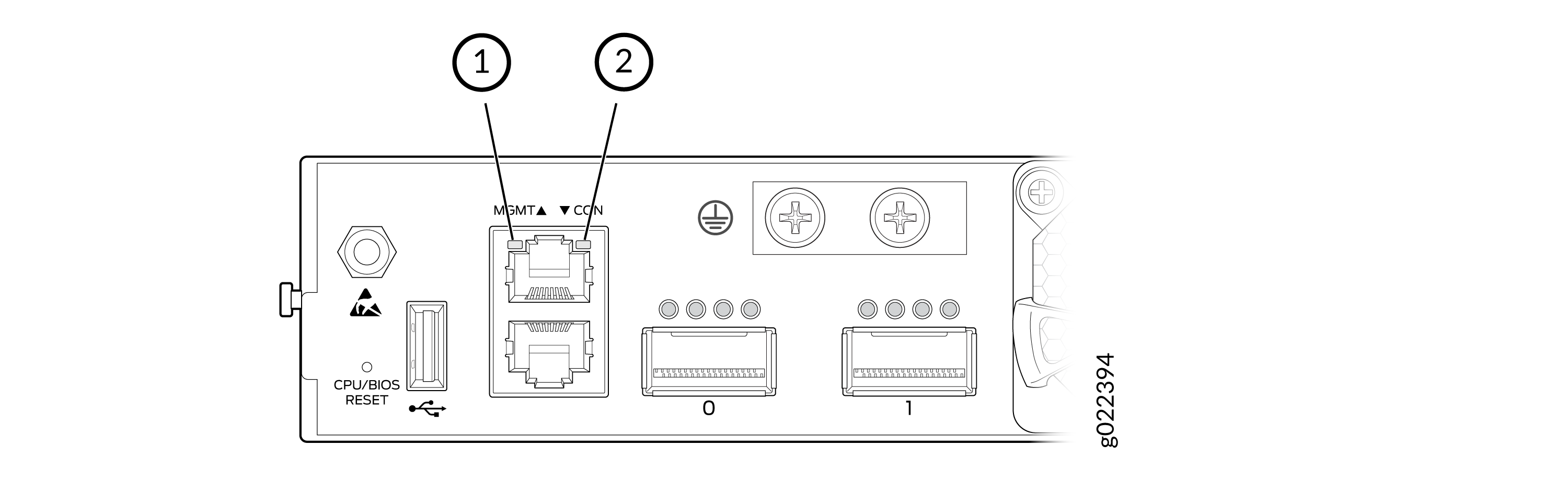
1 — Link activity LED | 2 — Status LED |
| Callout | Label | LED | Color | State and Description |
|---|---|---|---|---|
|
1 |
MGMT |
Link/ Activity |
Green |
|
|
2 |
Status |
Green/amber |
|
RJ-45 Network Port Status LEDs
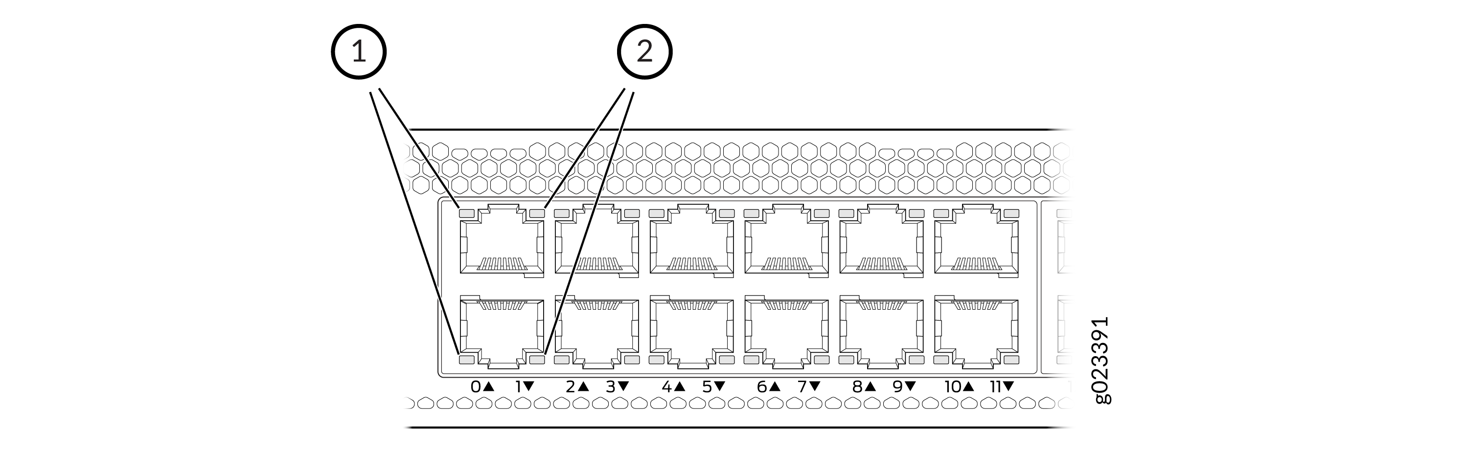
1 — Link activity LED | 2 — Status LED |
| Callout | LED | Colors | State and Description |
|---|---|---|---|
|
1 |
Link activity |
Green |
|
|
2 |
Status |
Green, amber, blue |
|
QSFP28 Stacking Ports LEDs
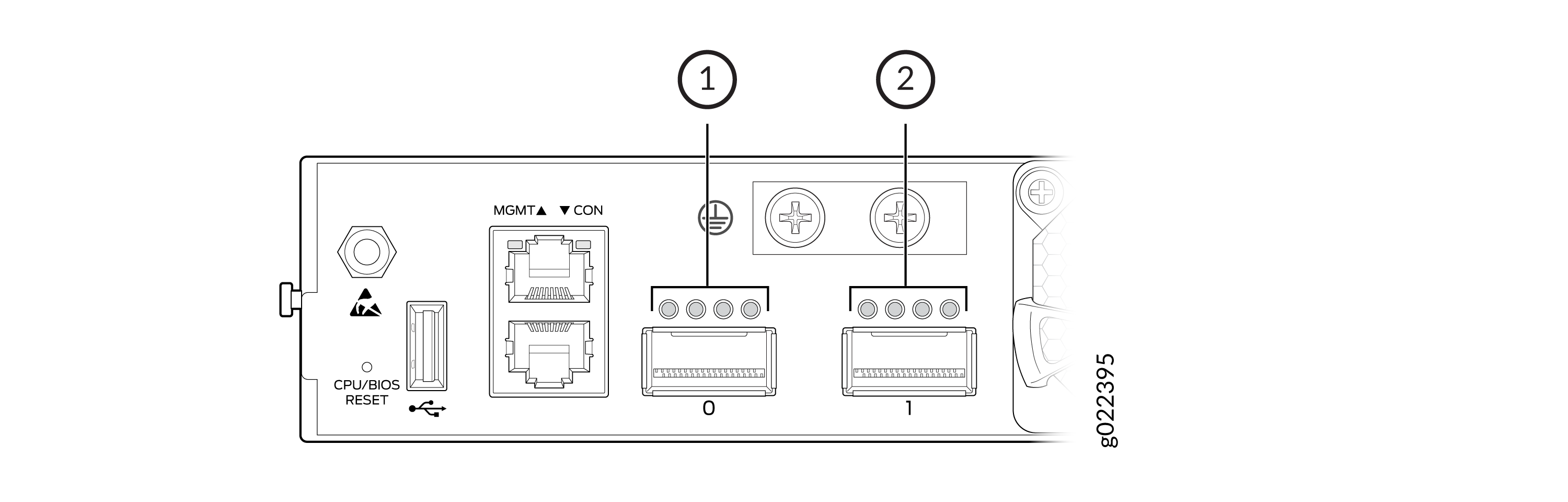
1 — LED of the first QSFP28 Stacking Port | 2 — LED of the second QSFP28 Stacking Port |
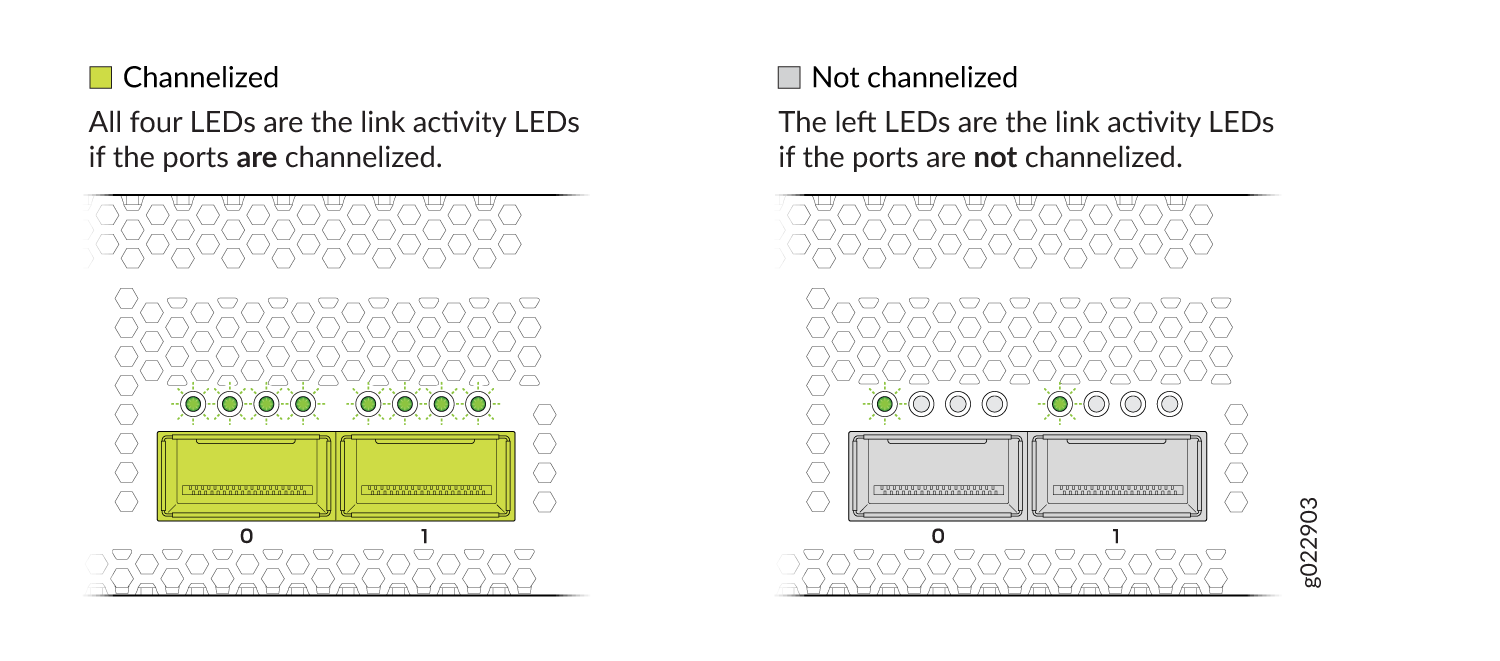
| LED | Color | State and Description |
|---|---|---|
|
Link activity (non-channelized ports) |
Green |
|
|
Amber |
|
|
|
All four LEDs (channelized ports). The LEDs correspond to the four channels. |
Green |
|
|
Amber |
|
LEDs on the Extension Module Ports
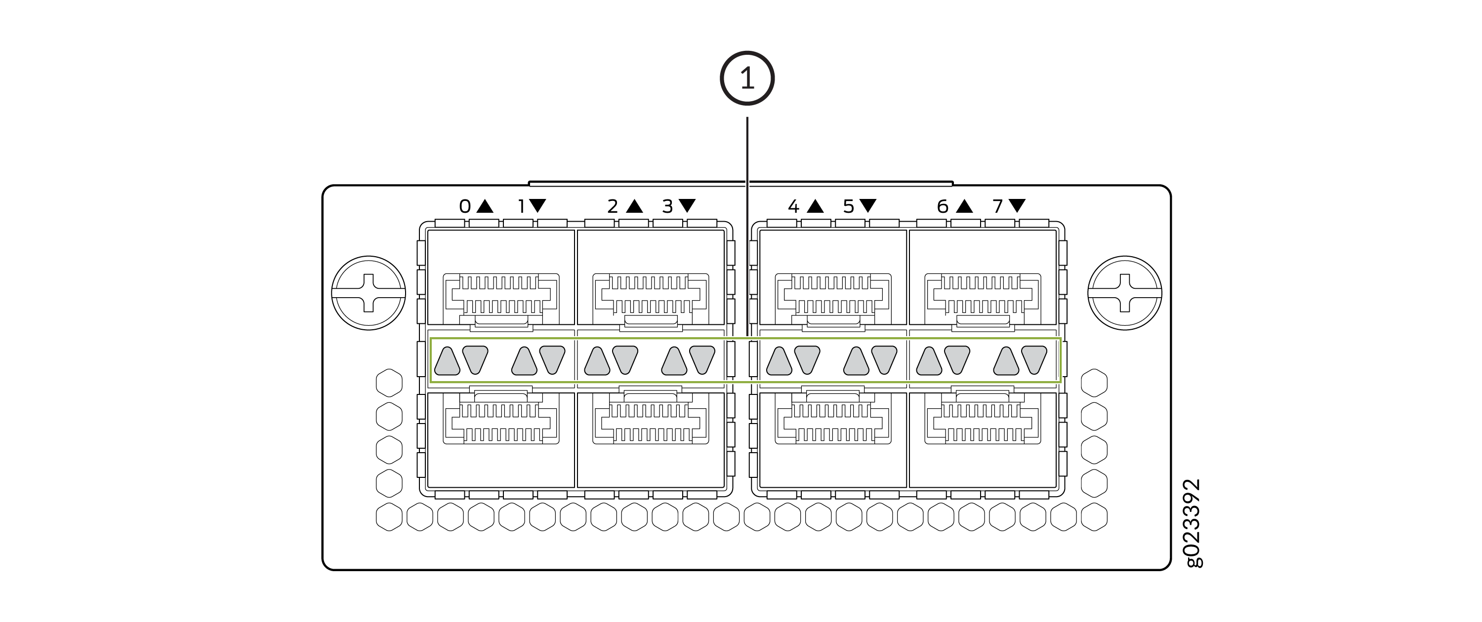
1 — LEDs on the extension module ports |
| LED | LED Type | Colors | State and Description |
|---|---|---|---|
|
Left |
Link Activity |
Green |
|
|
Right |
Status |
Green |
|
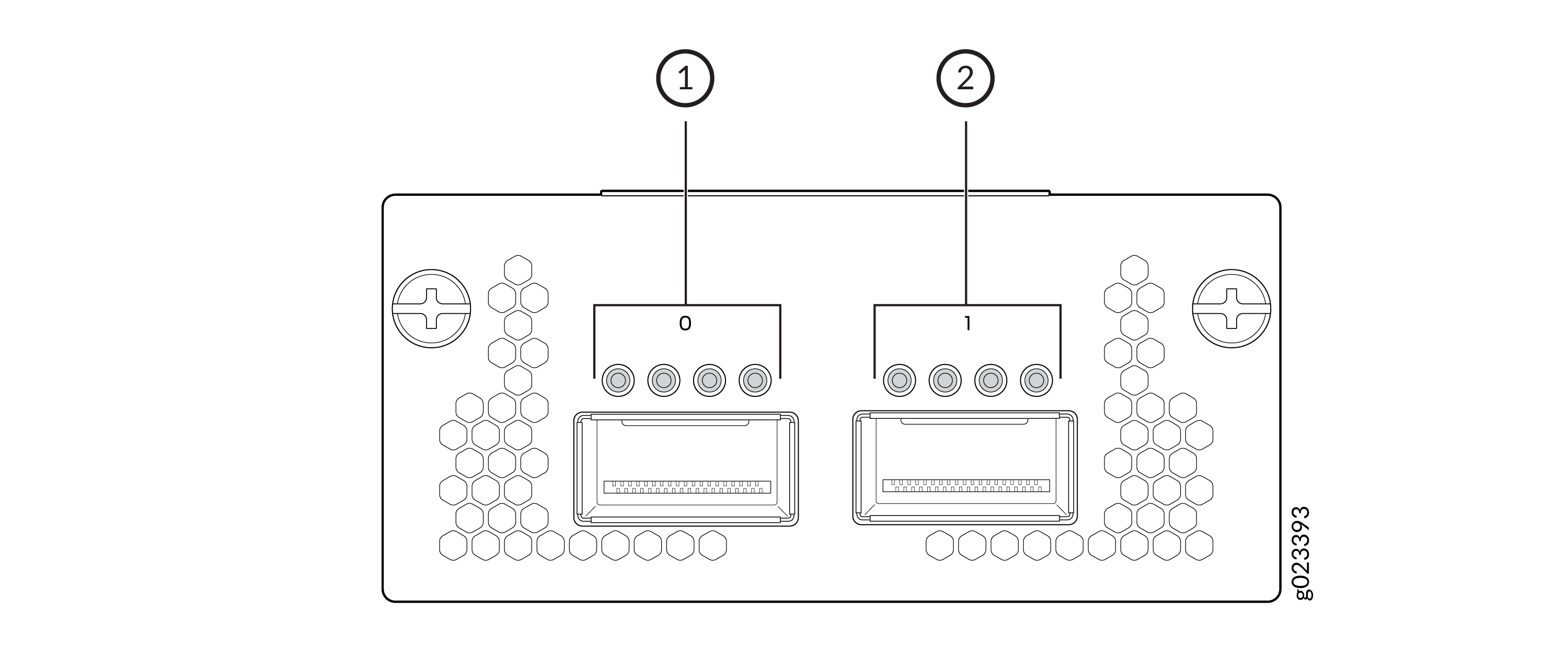
1 — LEDs on the first extension module port | 2 — LEDs on the second extention module port |
| LED | LED Type | Colors | State and Description |
|---|---|---|---|
|
Left first one |
Link Activity and Speed |
Green |
|
|
Amber |
|
||
|
All four |
Link Activity and Speed |
Green |
|
|
Amber |
|