ON THIS PAGE
EX5200 Switch Models
This topic provides details of the EX5200 switch models and their specifications, information on the number and types of ports in each models, and the components in the shipment for each model.
The EX5200 switch models consist of both PoE (multigigabit) and non-PoE (multigigabit) models. These devices run on AC power and support front-to-back airflow.
|
Model |
AC variant |
DC variant |
Front-to-back Airflow |
Back-to-front Airflow |
PoE++ |
|---|---|---|---|---|---|
|
EX5200-24MP |
Yes |
No |
Yes |
No |
Yes |
|
EX5200-24T |
Yes |
No |
Yes |
No |
No |
|
EX5200-48MP |
Yes |
No |
Yes |
No |
Yes |
|
EX5200-48T |
Yes |
No |
Yes |
No |
No |
The AIR OUT label and the Juniper Gold handle indicates front-to-back airflow.
EX5200-24MP
Components on the Front and Rear Panels
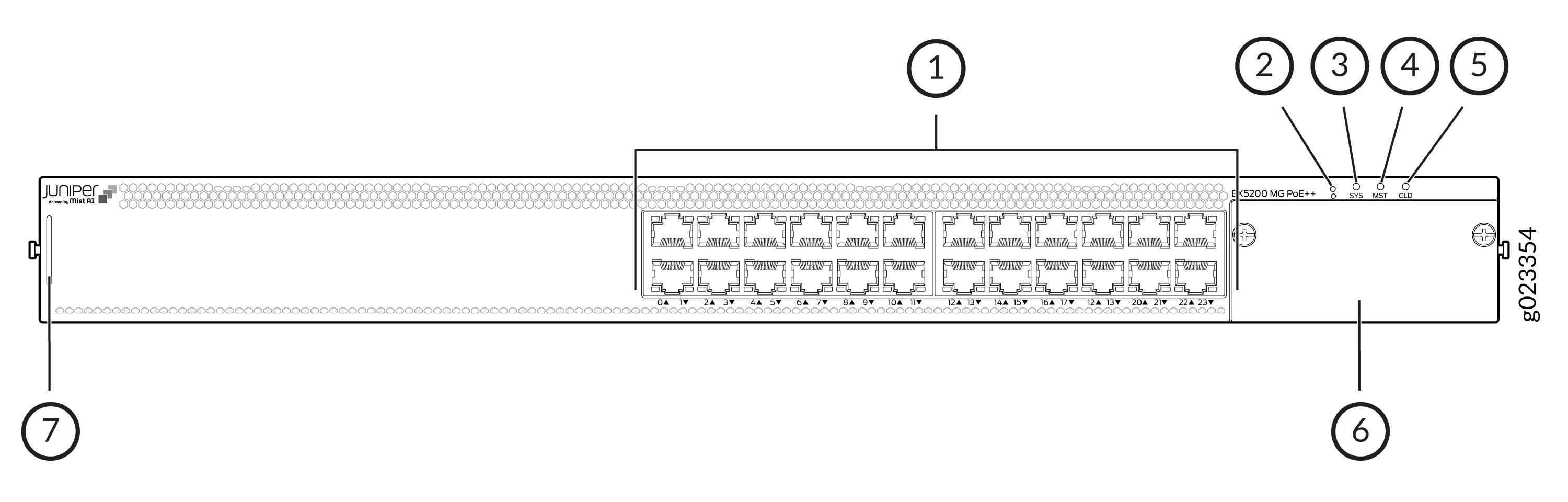
| Callout | Item | Description |
|---|---|---|
|
1 |
24 multigigabit PoE++ RJ-45 ports |
The 24 multigigabit PoE++ RJ-45 ports support MACSec and speeds of 100M, 1G, 2.5G, 5G, and 10G. |
|
2 |
Reset |
Front-panel pin hole button reset button for factory-default/Zeroize |
|
3 4 5 |
LEDs (SYS, MST, CLD) |
SYS shows system and Junos OS status, MST indicates Virtual Chassis master/backup/linecard status, and CLD displays cloud (Mist) management and connectivity states |
|
6 |
Uplink module |
Supported uplink modules: 8 x 25GE SFP28 and 2 x 100G QSFP28 with MACSec |
|
7 |
Pull-out tab |
Pull-out tab to show Claim Code (QR) and serial number of chassis. Push the tab in after use. |
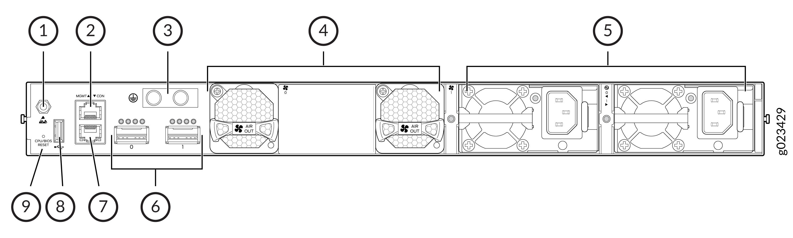
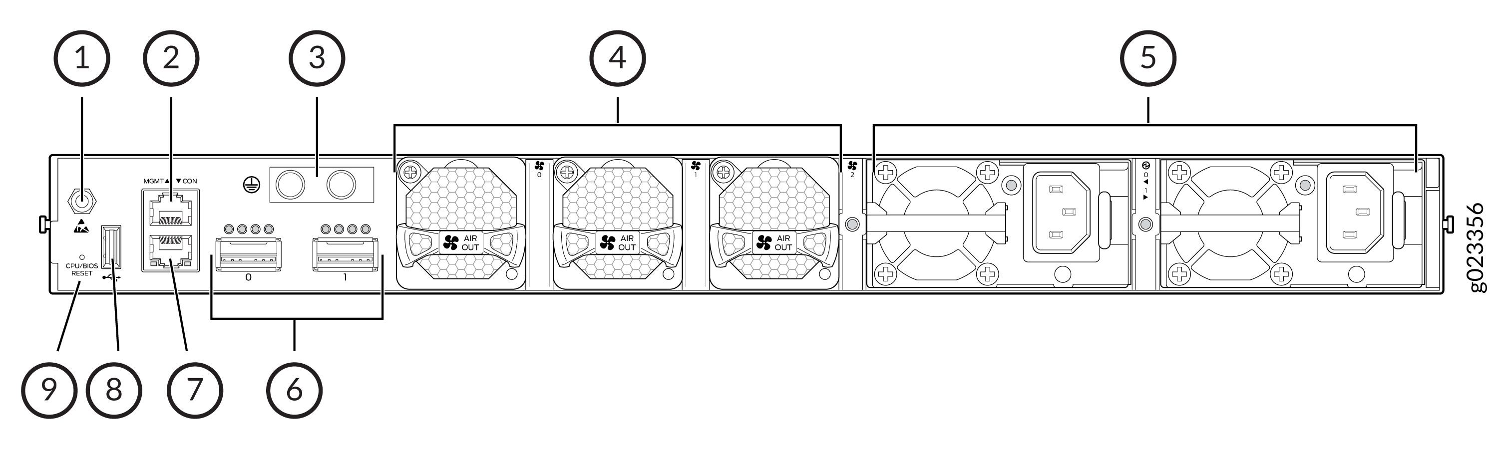
| Callout | Item | Description |
|---|---|---|
|
1 |
ESD point |
The ESD (Electrostatic Discharge) point is a dedicated grounding connection used to safely attach an antistatic wrist strap while you install or service internal part. |
|
2 |
Management port |
One 1000/100/10M RJ-45 Management port |
|
3 |
Grounding points |
Grounding points |
|
4 |
Fans |
2 AFO Fans |
|
5 |
PSUs |
2 AC PSU slots |
|
6 |
2 stacking ports |
2 x 100G QSFP28 |
|
7 |
Console port |
One RJ-45 type RS232 console port |
|
8 |
USB port |
1 standard USB 3.0/2.0 Type-A port |
|
9 |
Rear Panel CPU Reset/BIOS Swizzle pin hole reset button |
Rear Panel CPU Reset/BIOS Swizzle pin hole reset button |
EX5200-24MP Power System and Cooling System
| Component | Slots | Shipped | Notes |
|---|---|---|---|
|
Power supplies |
2 |
One 1600 W AC PSU FRU pre-installed |
You can order the redundant 1600 W AC PSU separately. |
|
Fan modules |
2 |
2 AFO Fan FRUs pre-installed |
2 AFO Fan FRUs pre-installed |
EX5200-24T
Components on the Front and Rear Panels
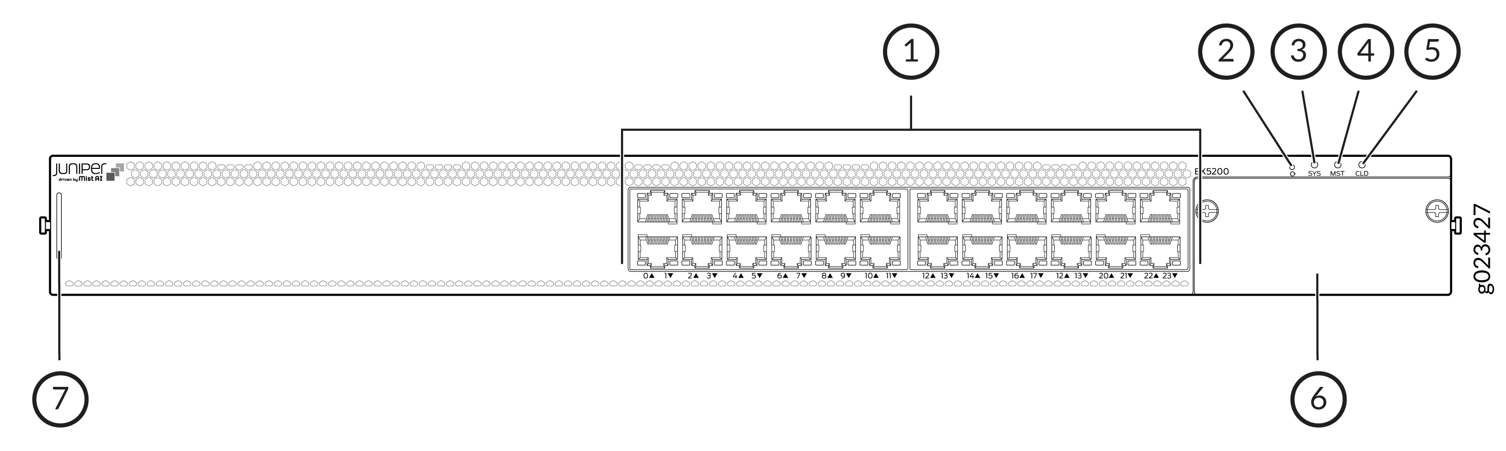
| Callout | Item | Description |
|---|---|---|
|
1 |
24 multigigabit non-PoE RJ-45 ports |
The 24 multigigabit non-PoE RJ-45 ports support MACSec and speeds of 100M, 1G, 2.5G, 5G, and 10G. |
|
2 |
Reset button |
Front-panel pin hole button reset button for factory-default/Zeroize |
|
3 4 5 |
LEDs (SYS, MST, CLD) |
SYS shows system and Junos OS status, MST indicates Virtual Chassis master/backup/linecard status, and CLD displays cloud (Mist) management and connectivity states |
|
6 |
Uplink module |
Supported uplink modules: 8 x 25GE SFP28 and 2 x 100G QSFP28 with MACSec |
|
7 |
Pull-out tab |
Pull-out tab to show Claim Code (QR) and serial number of chassis. Push the tab in after use. |
| Callout | Item | Description |
|---|---|---|
|
1 |
ESD point |
The ESD (Electrostatic Discharge) point is a dedicated grounding connection used to safely attach an antistatic wrist strap while you install or service internal part. |
|
2 |
Management port |
One 1000/100/10M RJ-45 Management port |
|
3 |
Grounding points |
Grounding points |
|
4 |
Fans |
2 AFO Fans |
|
5 |
PSUs |
2 AC PSU slots |
|
6 |
2 stacking ports |
2 x 100G QSFP28 |
|
7 |
Console port |
One RJ-45 type RS232 console port |
|
8 |
USB port |
1 standard USB 3.0/2.0 Type-A port |
|
9 |
Rear Panel CPU Reset/BIOS Swizzle pin hole reset button |
Rear Panel CPU Reset/BIOS Swizzle pin hole reset button |
EX5200-24T Power System and Cooling System
| Component | Slots | Shipped | Notes |
|---|---|---|---|
|
Power supplies |
2 |
One 550 W AC PSU FRU pre-installed |
You can order the redundant 550 W AC PSU separately. |
|
Fan modules |
2 |
2 AFO Fan FRUs pre-installed |
2 AFO Fan FRUs pre-installed |
EX5200-48MP
Components on the Front and Rear Panels
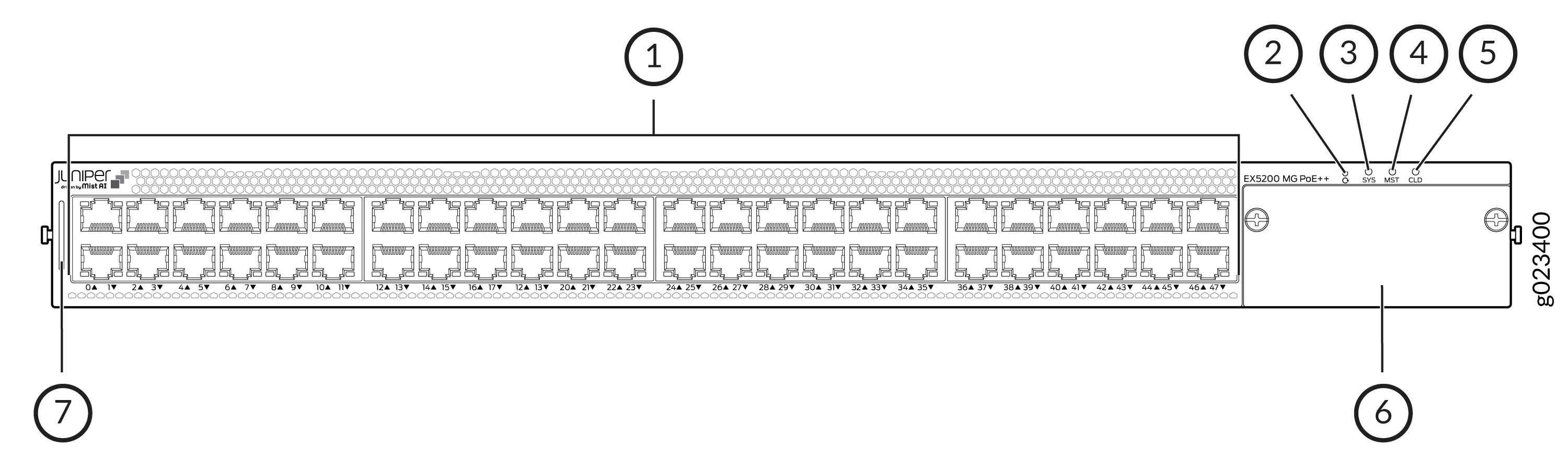
| Callout | Item | Description |
|---|---|---|
|
1 |
48 multigigabit PoE++ RJ-45 ports |
The 48 multigigabit PoE++ RJ-45 ports support MACSec and speeds of 100M, 1G, 2.5G, 5G, and 10G. |
|
2 |
Reset button |
Front-panel pin hole button reset button for factory-default/Zeroize |
|
3 4 5 |
LEDs (SYS, MST, CLD) |
SYS shows system and Junos OS status, MST indicates Virtual Chassis master/backup/linecard status, and CLD displays cloud (Mist) management and connectivity states |
|
6 |
Uplink module |
Supported uplink modules: 8 x 25GE SFP28 and 2 x 100G QSFP28 with MACSec |
|
7 |
Pull-out tab |
Pull-out tab to show Claim Code (QR) and serial number of chassis. Push the tab in after use. |
| Callout | Item | Description |
|---|---|---|
|
1 |
ESD point |
The ESD (Electrostatic Discharge) point is a dedicated grounding connection used to safely attach an antistatic wrist strap while you install or service internal part. |
|
2 |
Management port |
One 1000/100/10M RJ-45 Management port |
|
3 |
Grounding points |
Grounding points |
|
4 |
Fans |
3 AFO Fans |
|
5 |
PSUs |
2 AC PSU slots |
|
6 |
2 stacking ports |
2 x 100G QSFP28 |
|
7 |
Console port |
One RJ-45 type RS232 console port |
|
8 |
USB port |
1 standard USB 3.0/2.0 Type-A port |
|
9 |
Rear Panel CPU Reset/BIOS Swizzle pin hole reset button |
Rear Panel CPU Reset/BIOS Swizzle pin hole reset button |
EX5200-48MP Power System and Cooling System
| Component | Slots | Shipped | Notes |
|---|---|---|---|
|
Power supplies |
2 |
One 2000 W AC PSU FRU pre-installed |
You can order the redundant 2000 W AC PSU separately. |
|
Fan modules |
3 |
3 AFO Fan FRUs pre-installed |
3 AFO Fan FRUs |
EX5200-48T
- Components on the Front and Rear Panels
- EX5200-48T Power System and Cooling System
- Reset Button Functionality
Components on the Front and Rear Panels
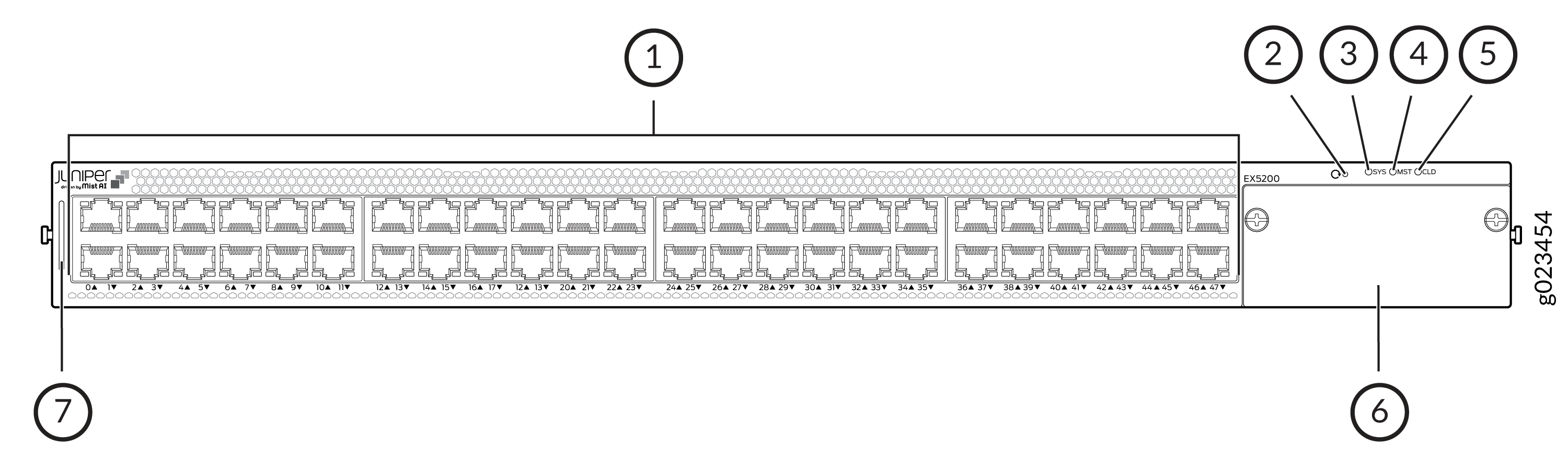
| Callout | Item | Description |
|---|---|---|
|
1 |
48 multigigabit non-PoE RJ-45 ports |
The 48 multigigabit non-PoE RJ-45 ports support MACSec and speeds of 100M, 1G, 2.5G, 5G, and 10G. |
|
2 |
Reset button |
Front-panel pin hole button reset button for factory-default/Zeroize |
|
3 4 5 |
LEDs (SYS, MST, CLD) |
SYS shows system and Junos OS status, MST indicates Virtual Chassis master/backup/linecard status, and CLD displays cloud (Mist) management and connectivity states |
|
6 |
Uplink module |
Supported uplink modules: 8 x 25GE SFP28 and 2 x 100G QSFP28 with MACSec |
|
7 |
Pull-out tab |
Pull-out tab to show Claim Code (QR) and serial number of chassis. Push the tab in after use. |
| Callout | Item | Description |
|---|---|---|
|
1 |
ESD point |
The ESD (Electrostatic Discharge) point is a dedicated grounding connection used to safely attach an antistatic wrist strap while you install or service internal part. |
|
2 |
Management port |
One 1000/100/10M RJ-45 Management port |
|
3 |
Grounding points |
Grounding points |
|
4 |
Fans |
2 AFO Fans |
|
5 |
PSUs |
2 AC PSU slots |
|
6 |
2 stacking ports |
2 x 100G QSFP28 |
|
7 |
Console port |
One RJ-45 type RS232 console port |
|
8 |
USB port |
1 standard USB 3.0/2.0 Type-A port |
|
9 |
Rear Panel CPU Reset/BIOS Swizzle pin hole reset button |
Rear Panel CPU Reset/BIOS Swizzle pin hole reset button |
EX5200-48T Power System and Cooling System
| Component | Slots | Shipped | Notes |
|---|---|---|---|
|
Power supplies |
2 |
One 550 W AC PSU FRU pre-installed |
You can order the redundant 550 W AC PSU separately. |
|
Fan modules |
2 |
2 AFO Fan FRUs pre-installed |
2 AFO Fan FRUs |
Reset Button Functionality
On EX5200, there is a reset button/pin hole button on the rear side and front side of the switch. Users will require a special pointy object like a sim remover which can be inserted in the pin hole to access this button. The tool will not be provided with the system.
Front panel reset button functionality
|
Front Panel Pin hole reset button (time) |
Action |
Details |
LED Behavior |
|---|---|---|---|
|
Press for more than 5 seconds (less than 10 seconds) |
Factory reset |
Factory reset via pinhole button press: When pinhole button is pressed for more than 5 seconds (less than 10 seconds) and released then factory reset will be triggered. Users will see factory reset related messages on console. Additional indication is provided to convey factory reset has been triggered via SYS LEDs |
When factory reset via pinhole button is triggered, SYS Led will turn blue for few seconds and then color of SYS will be restored depending on status of switch. |
|
Press for more than 10 seconds and released |
Zeroize |
Zeroize via pinhole button press: When pinhole button is pressed for more than 10 seconds and released then zeroize will be triggered. To indicate users of zeroize operation, SYS Led will turn purple till the switch is rebooted during zeroize operation. |
SYS LED will turn purple till the switch is rebooted during zeroize operation |
Rear panel reset button functionality
|
Rear Panel Pin hole reset button (time) |
Action |
Details |
LED Behavior |
|---|---|---|---|
|
Press between 0 to 5 secs. |
Board Reset |
Soft reboot |
No LED pattern |
|
Press between 5 to 10 secs. |
BIOS Swizzle |
BIOS recovery |
No LED pattern |