Configure DHCP Server or Relay on a Switch
Follow these steps to configure DHCP server or relay on a switch.
Prerequisites
Before configuring the DHCP server or relay, ensure the following:
- The VLAN for which DHCP server will be configured on switch is assigned to the ports connecting to the DHCP clients. You can do this by applying a relevant port profile to the port. For more information about port profiles, see Static and Dynamic Port Profiles.
- The switch has a Static IP Configuration or Additional IP configuration for the network to run DHCP server. Or the L3 Interface is configured for DHCP server or relay.
See Wired Clients for information on displaying DHCP client properties in the Wired Clients list.
Configure DHCP Server
To configure DHCP server on a switch:
-
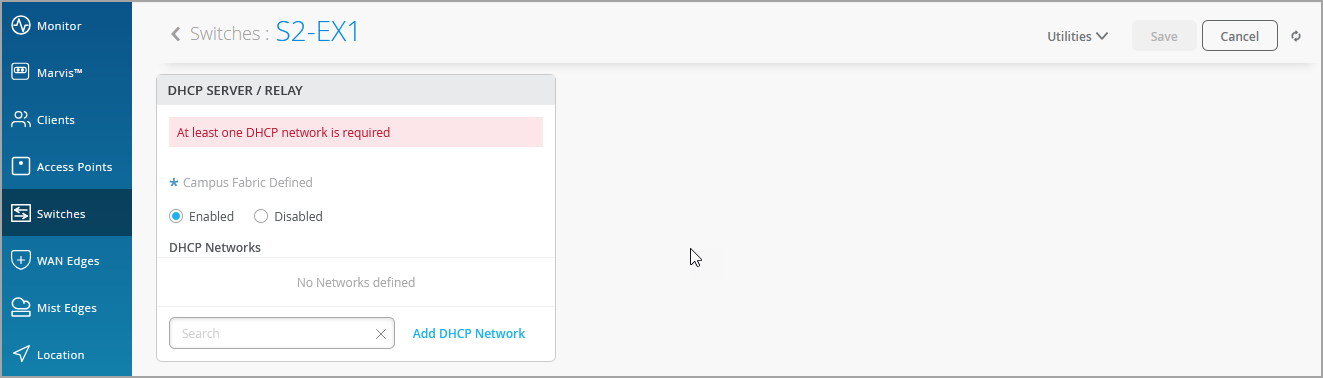
On the switch details page, scroll down to the DHCP Server /
Relay tile in the Services section.
-
Specify the following fields:
-
IP Start—The starting IP address within the DHCP IP address assignment pool.
-
IP End—The ending IP address within the DHCP IP address assignment pool.
-
Gateway—Default gateway for the DHCP client. Usually, it is the switch IRB IP address for the corresponding network.
-
DNS Servers (Optional)—You can add up to three DNS IP addresses in a comma separated format.
-
DNS Suffix (Optional)—You can add up to three domain suffixes in a comma separated format.
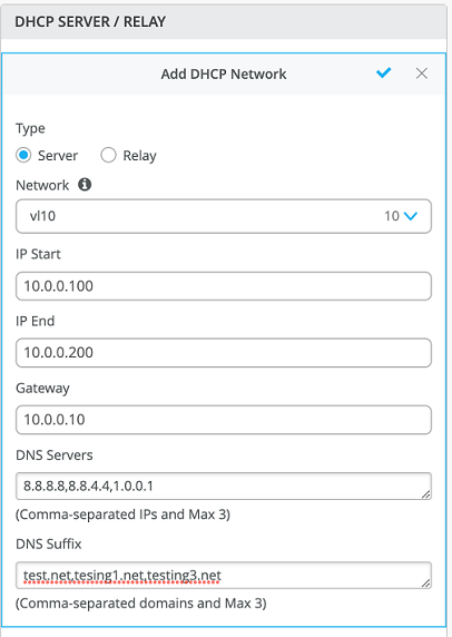
If you do not configure the DNS Servers and DNS Suffix, Mist auto-generates the configuration by taking DNS servers and DNS Suffix configured at the switch level.
-
-
Save the changes.
The following configuration will be applied to the API
/sites/:site-id/devices/device-id: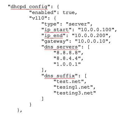
Check the corresponding intended configuration to be pushed to the following API:
/sites/:site-id/devices/device-id/config_cmdThe DHCP server is enabled on the irb.10 interface for the vl10. The following example applies to Junos switches:
set groups top system services dhcp-local-server group vl10 interface irb.10
The address assignment pool configuration looks like the below (applicable to Junos switches):
"set groups top access address-assignment pool vl10 family inet network 10.0.0.0/24",
"set groups top access address-assignment pool vl10 family inet range vl10 low 10.0.0.100",
"set groups top access address-assignment pool vl10 family inet range vl10 high 10.0.0.200",
"set groups top access address-assignment pool vl10 family inet dhcp-attributes name-server 8.8.8.8",
"set groups top access address-assignment pool vl10 family inet dhcp-attributes name-server 8.8.4.4",
"set groups top access address-assignment pool vl10 family inet dhcp-attributes name-server 1.0.0.1",
"set groups top access address-assignment pool vl10 family inet dhcp-attributes router 10.0.0.10",
"set groups top access address-assignment pool vl10 family inet dhcp-attributes option 15 array string test.net",
"set groups top access address-assignment pool vl10 family inet dhcp-attributes option 15 array string tesing1.net",
"set groups top access address-assignment pool vl10 family inet dhcp-attributes option 15 array string testing3.net,"
-
Verify the configuration on the switch by using the following CLI. The
following example is applicable to Junos switches:
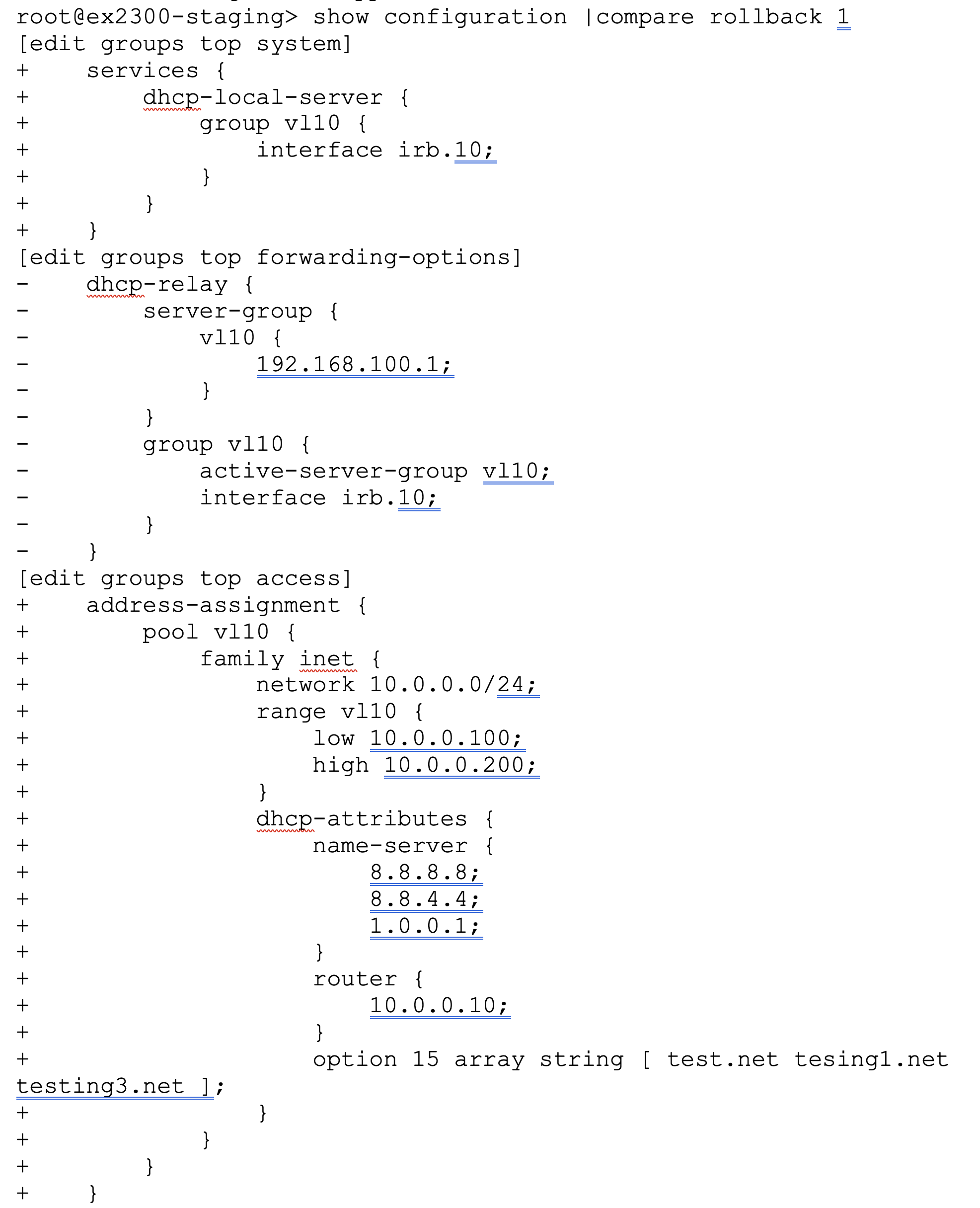
The DHCP clients for v110 networks should now be assigned IP address by DHCP server as shown below:
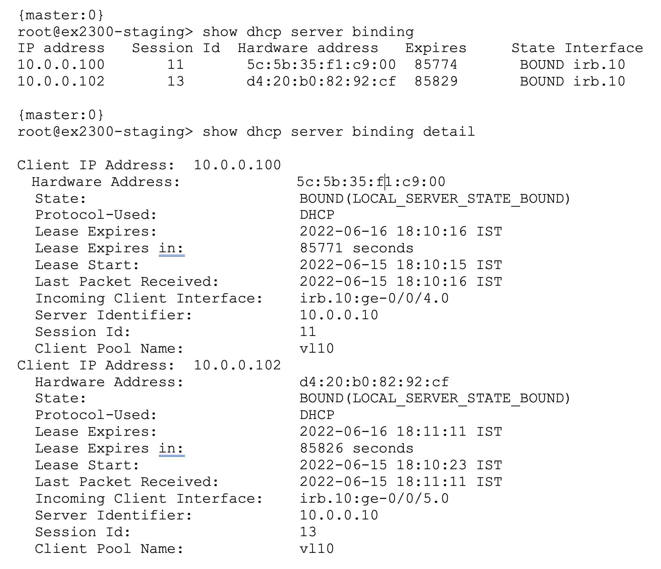
The example above apply to Junos switches.
Here are some useful Junos CLI commands:
-
show dhcp server bindingorshow dhcp server binding detail—To view the DHCP server binding information. show dhcp server statistics—To view the DHCP messages sent/received statistics.clear dhcp server binding interface x-x/x/x—To clear the DHCP client binding for a client on a particular interface.clear dhcp server binding <address>—To clear the DHCP client binding based on an IP address or MAC address of the wired client.
Configure DHCP Relay
To configure DHCP relay on a switch:
-
On the switch details page, scroll down to the DHCP Server /
Relay tile in the Services section.
-
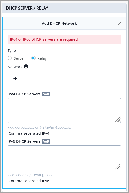
Select Relay as configuration
Type.
-
Save the changes.
The following configuration will be applied to the API
/sites/:site-id/devices/device-id: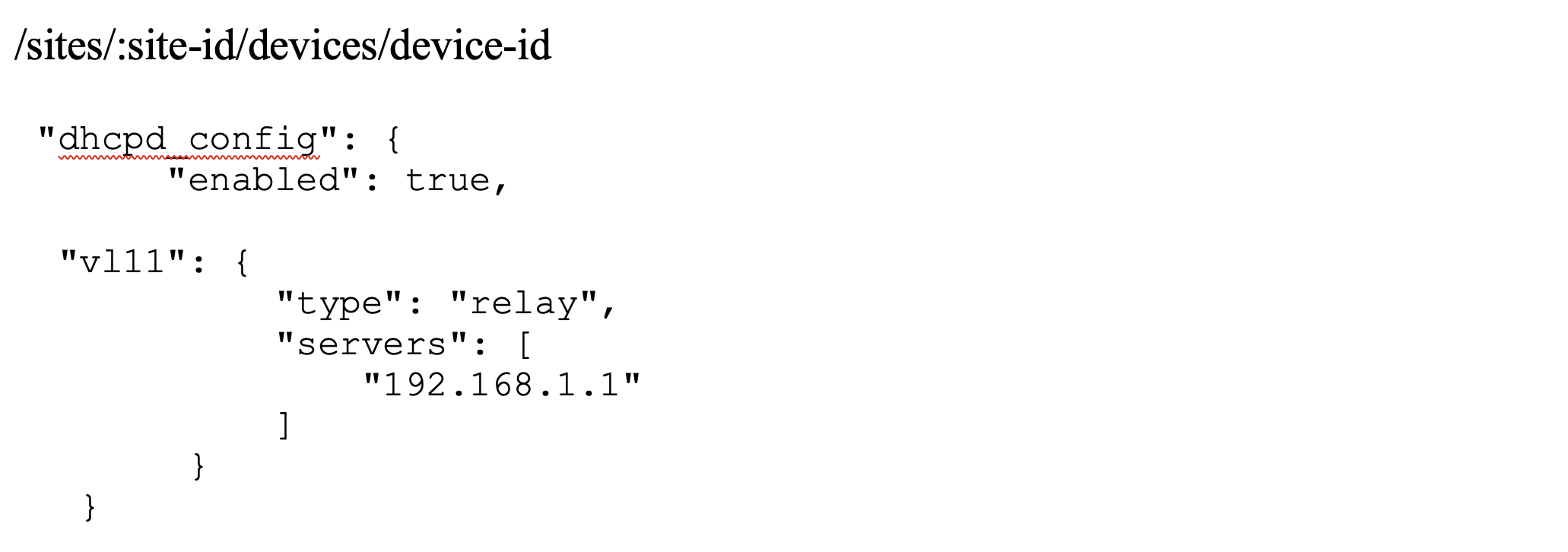
Check the corresponding intended configuration to be pushed on following API:
/sites/:site-id/devices/device-id/config_cmdThe configuration looks like the below (this example apply to Junos switches):
"set groups top forwarding-options dhcp-relay server-group v111 192.168.1.1",
"set groups top forwarding-options dhcp-relay server-group v111 interface irb.11",
"set groups top forwarding-options dhcp-relay server-group v111 active server group v111",
-
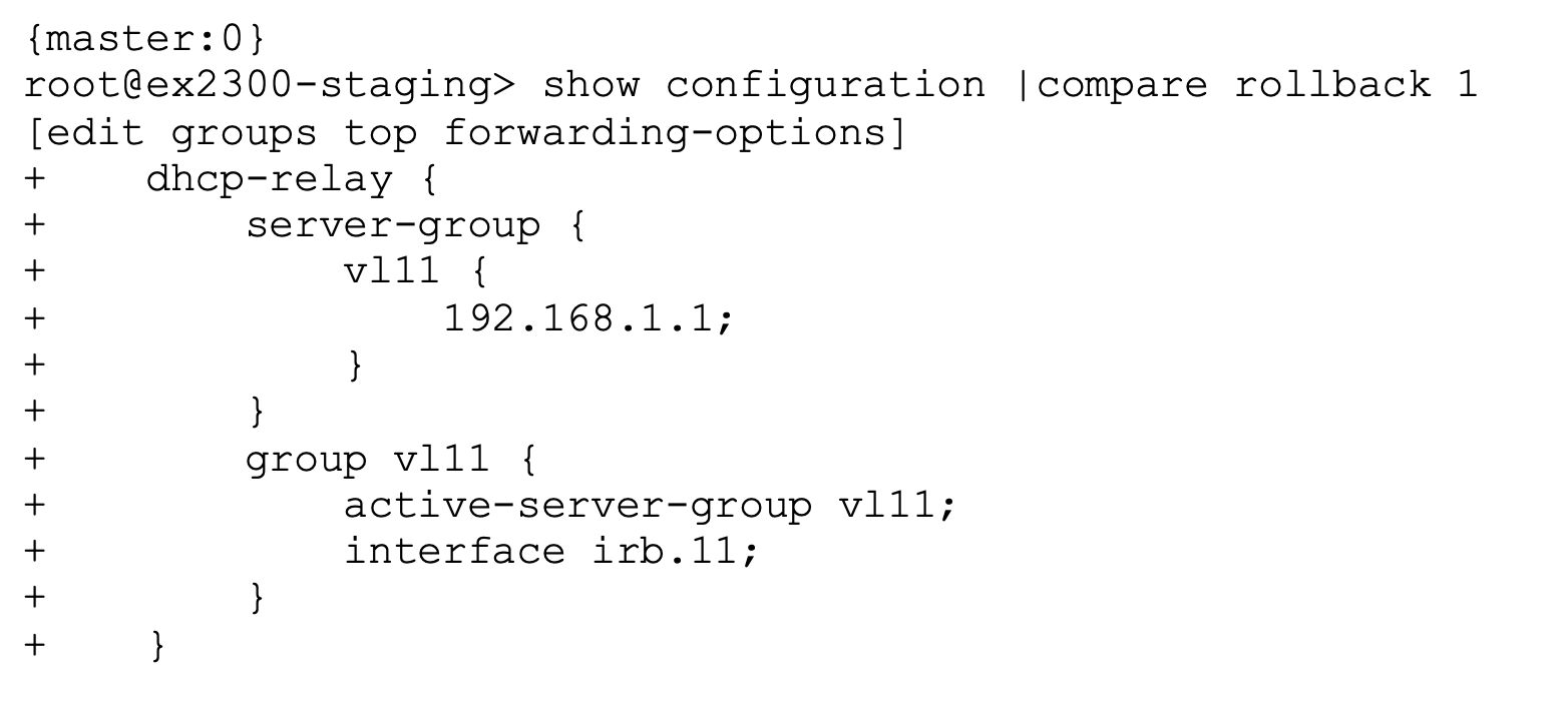
Verify the configuration on the switch using the following CLI. The
following sample CLI commands apply to Junos switches:
-
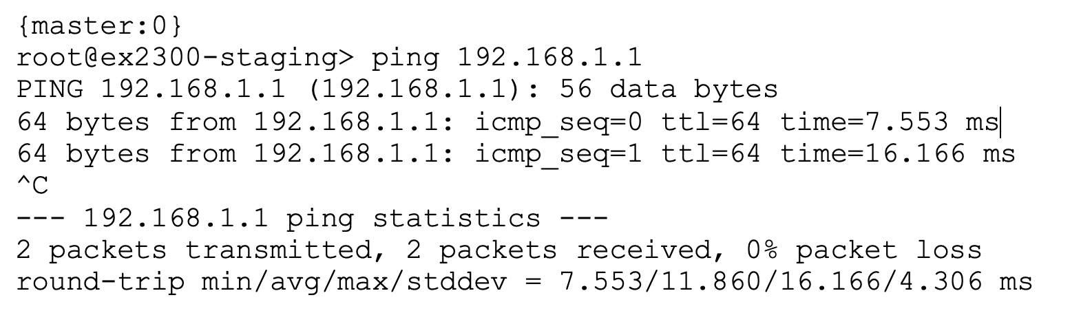
Make sure the remote DHCP server is reachable from the switch. The
following sample CLI commands apply to Junos switches:
-
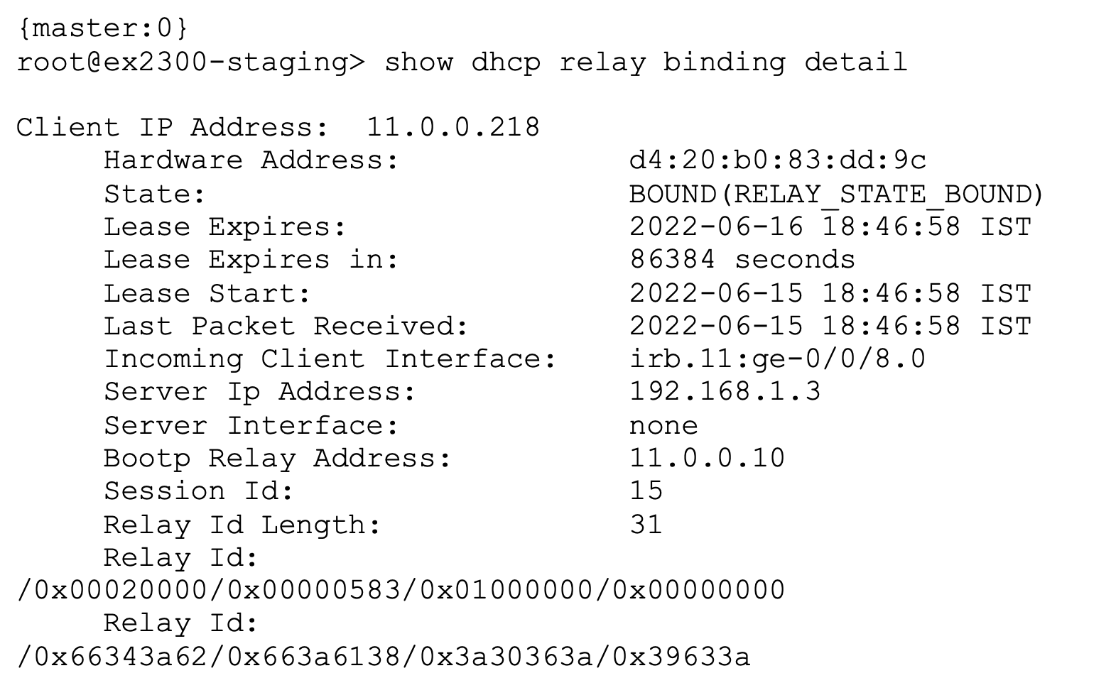
Verify DHCP relay binding on the switch. The following sample CLI commands
apply to Junos switches:
See also: DHCP Relay Agent.