CoS on NextGen Port Extender
NGPE provides a method of significantly expanding the number of available network interfaces on an aggregation device by allowing the aggregation device to add interfaces through interconnections with satellite devices. The entire system—the interconnected aggregation device and satellite devices—is called NGPE. NGPE simplifies network administration by appearing in the network topology as a single device, and the single device is managed from a single IP address.
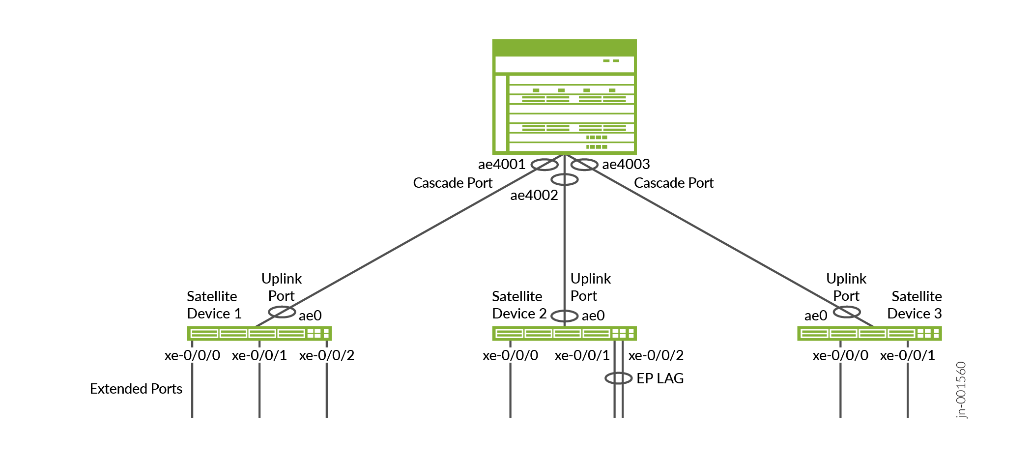
The following figure is a sample topology of a small-scale NGPE deployment. Cascade and uplink ports are bundled as aex. Extended ports on the satellites are represented on the AD as virtual ports.
This topic describes class of service (CoS) on the different types of ports in NGPE.
Overview of CoS on Different Types of Ports in NGPE
Figure 2 provides an overview of packet flow through NGPE and how CoS features are applied at the different ports.
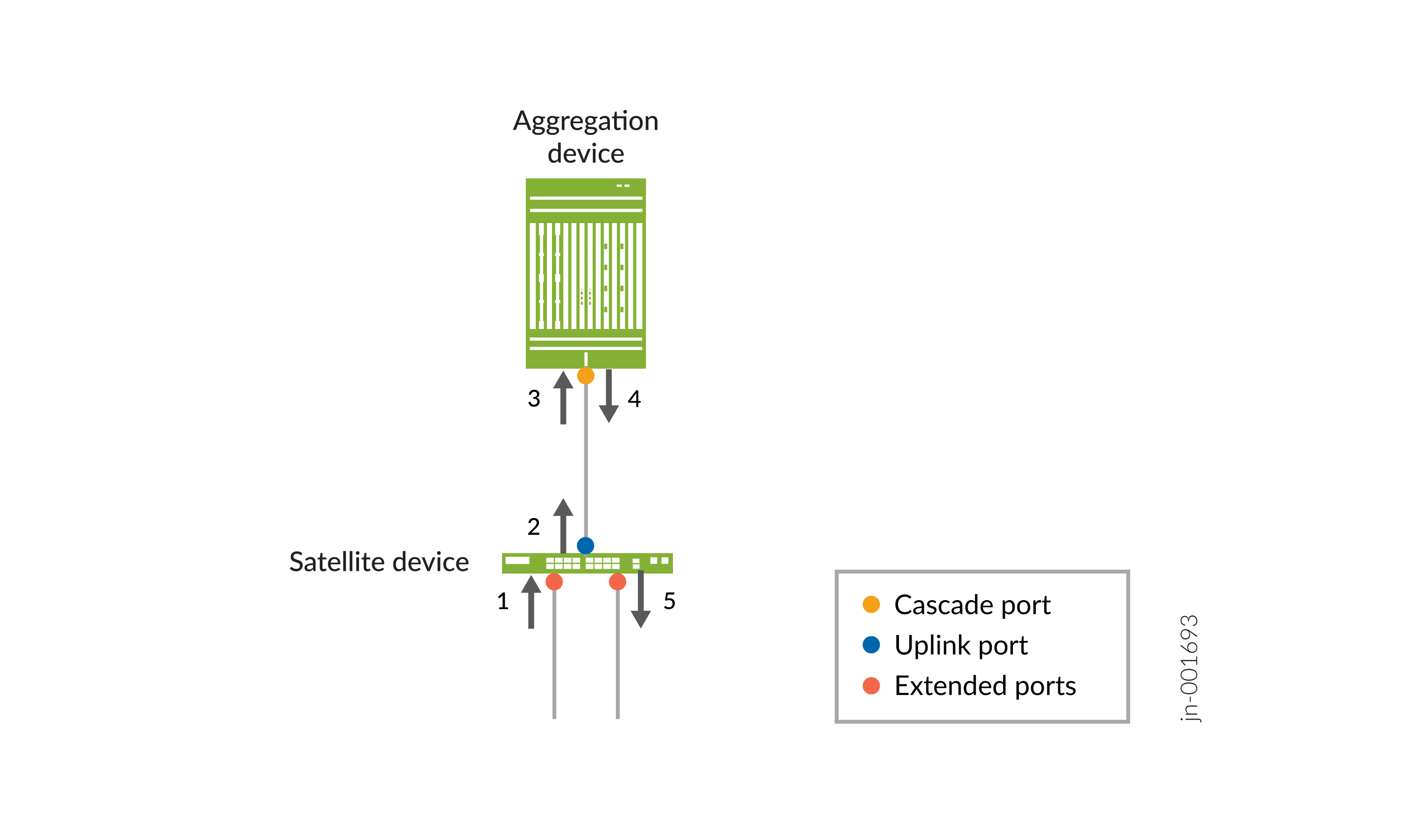
All configuration for CoS policies for NGPE is done on the aggregation device. For CoS policies that you define for extended ports, however, different portions of that policy are applied at different points in a packet’s path through NGPE. From Figure 2:
As a packet enters an extended port, any default CoS rules as per the satellite device capabilities get applied.
The packet gets VXLAN encapsulated and is sent by the uplink port to the aggregation device. Default CoS policies of the satellite device uplink port get applied on the encapsulated packet.
As the packet enters the aggregation device at the cascade port, the VXLAN header is removed from the original packet. Any multifield classifiers, policers, or logical interface-level BA classifiers you define for the ingress extended port are applied.
As the packet exits the aggregation device at the cascade port, any rewrite rules you define for the egress extended port are applied. The packet is then again VXLAN encapsulated and any schedulers present for the cascade ports are applied before the packet travels from the cascade port to the satellite device.
Note:The VXLAN encapsulation as the packet exits the aggregation device at the cascade port adds 54 bytes to the header, which would normally diminish the configured shaping rate when the packet eventually exits the satellite device at the extended port. To compensate, Junos counts these 54 bytes while doing shaping-rate computations so that the desired shaping-rate bandwidth as available at the extended port. Because of this additional accounting, if the cascade port interface speed is exceeded, CoS queue statistics will indicate a throughput less than the line-rate of the interface.
If you configure overhead accounting on an extended port, for example:
user@host# set class-of-service traffic-control-profiles tcp1 overhead-accounting ?
Possible completions:
  bytes                             Byte adjust value (-120..124)
  cell-mode                     Cell mode
  cell-mode-bytes         Overhead bytes when in cell-mode (-120..124)
  frame-mode                Frame mode
  frame-mode-bytes    Overhead bytes when in frame-mode (-120..124)
because the VXLAN encapsulation added 54 bytes to the header, the actual lower range becomes -120 + 54 = -66 bytes.
Finally, the packet is VXLAN decapsulated at the ingress port of the satellite device uplink port. Default CoS policies based on the satellite device capabilities are applied, and the packet egresses the physical extended port of the satellite device.
The following sections provide further information about implementing CoS on each port type in NGPE.
Per-unit and Hierarchical Scheduling on Extended Ports
NGPE supports per-unit and hierarchical schedulers on extended ports. To support per-unit or hierarchical scheduling on an extended port, all cascade ports on the aggregation device for that extended port must have a queueing chip.
Multihomed satellite devices do not support per-unit and hierarchical scheduling.
To enable per-unit scheduling on an extended port, enable the
per-unit-scheduler option at the [edit interfaces
interface-name] hierarchy level for the extended
port.
To enable hierarchical scheduling on an extended port, enable the
hierarchical-scheduler option at the [edit interfaces
interface-name] hierarchy level for the extended
port.
If you enable hierarchical scheduling on an extended port, you must also explicitly configure schedulers at the interface set or VLAN level.
NGPE treats the cascade ports connecting the aggregation device to the satellite
device as aggregated Ethernet ports with aggregation done automatically without
configuration. By default the NGPE implementation of hierarchical CoS applies the
scheduler parameters across all cascade ports in scale mode.
Because scale mode divides the configured shaper equally across the
cascade ports, traffic drops can start before a customer reaches its committed rate
for a particular flow. You can set all cascade ports on an aggregation device to be
in replicate mode, thereby copying scheduler parameters to each
level of the aggregated interface member links, and automatically target all of an
extended port’s traffic to a specific cascade port. To do this, simply enable
target-mode for the satellite device at the [edit
chassis port-extender fpc fpc-number] hierarchy
level. For example:
[edit]
user@host# show chassis port-extender
fpc 100 {
    target-mode;
}
Enabling or disabling target-mode disrupts traffic on the
satellite device while extended ports are deleted and re-added and cascade ports
are reconfigured on the aggregate device.
CoS on Cascade Ports in NGPE
When a cascade port is created, three logical interfaces are automatically created:
-
Unit 0 for user-created logical interfaces to carry management traffic.
-
Unit 16384 for user-created logical interfaces to carry fabric/data traffic.
-
Unit 32767 for protocol control traffic.
Per-unit scheduling is automatically enabled on the cascade port to support multiple queues on each of the logical interfaces. All cascade ports must be configured on Modular Port Concentrators (MPCs) that support per-unit scheduling.
Let’s say, for example, that interface xe-0/0/4 is configured as a cascade port. The
command show interfaces xe-0/0/4 terse produces output similar to
the following:
user@agg-device# show interfaces et-0/0/4 terse
Interface               Admin Link Proto    Local                 Remote
et-0/0/4                up    up
et-0/0/4.0              up    up   aenet    --> ae4001.0
et-0/0/4.16384          up    up   aenet    --> ae4001.16384
et-0/0/4.32767          up    up   aenet    --> ae4001.32767
The control logical interface (unit 0) is automatically assigned an internal traffic control profile (__cp_control_tc_prof) that guarantees 50 Mbps of bandwidth for the logical interface, a 10 percent shaping rate, and the default scheduling policy. The default scheduling policy is applied to the data logical interface. For example:
user@agg-device# show class-of-service interface et-0/0/4
Physical interface: et-0/0/4, Index: 329
Maximum usable queues: 8, Queues in use: 4
Exclude aggregate overhead bytes: disabled
Logical interface aggregate statistics: disabled
  Scheduler map: <default>, Index: 2
  Congestion-notification: Disabled

  Logical interface: et-0/0/4.0, Index: 391
Object                  Name                   Type                    Index
Traffic-control-profile __cp_control_tc_prof   Output                  17228
Classifier              ipprec-compatibility   ip                         13

  Logical interface: et-0/0/4.16384, Index: 392
Object                  Name                   Type                    Index
Traffic-control-profile __cp_data_tc_prof      Output                  50776
Classifier              ipprec-compatibility   ip                         13

  Logical interface: et-0/0/4.32767, Index: 393
Object                  Name                   Type                    Index
Traffic-control-profile __control_tc_prof      Output                  45866
and:
user@agg-device# show class-of-service scheduler-hierarchy interface et-0/0/4
Interface/                              Shaping Guaranteed Guaranteed/   Queue   Excess
Resource name                              rate      rate       Excess  weight   weight
                                          kbits     kbits     priority          high/low
et-0/0/4                               100000000
  best-effort                          100000000 95000000      GL   EL      95
  network-control                      100000000  5000000      GL   EL       5
  et-0/0/4.0                            1000000     50000                          2    2
    best-effort                         1000000     47500      GL   EL      95
    network-control                     1000000      2500      GL   EL       5
  et-0/0/4.16384                       100000000  9950000                        500  500
    best-effort                        100000000  9452500      GL   EL      95
    network-control                    100000000   497500      GL   EL       5
  et-0/0/4.32767                       100000000     2000                          1    1
    best-effort                        100000000     1900      GL   EL      95
    network-control                    100000000      100      GL   EL       5
50 Mbps of bandwidth is reserved for the management logical interface, unit 0. 2 Mbps of bandwidth is reserved for the protocol control traffic on unit 32767. The remaining bandwidth is available to the data logical interface, interface 16384.
The default scheduling policy is applied to the data logical interface. This reserves 95 percent of the available bandwidth and buffer space for the best effort forwarding class (mapped to queue 0) and 5 percent for the network control forwarding class (mapped to queue 3).
We do not recommend customer CoS configuration on cascade ports.