NAT Configuration Components
Learn about NAT components, rule processing, and how to configure, verify, and troubleshoot NAT on Junos OS devices.
Use Feature Explorer to confirm platform and release support for specific features. Additional platforms might be supported.
NAT Rule Sets and Rules
This topic includes the following sections:
NAT Rule Sets
A rule set specifies a general set of traffic-matching conditions. For static NAT and destination NAT, a rule set specifies one of the following match criteria:
-
Source interface
-
Source zone
-
Source routing instance
For source NAT rule sets, you configure both source and destination conditions:
-
Source interface, zone, or routing instance
-
Destination interface, zone, or routing instance
-
Source interface/destination interface
-
Source zone/destination interface
-
Source routing instance/destination interface
-
Source interface/destination zone
-
Source zone/destination zone
-
Source routing instance/destination zone
-
Source interface/destination routing instance
-
Source zone/destination routing instance
-
Source routing instance/destination routing instance
For example, you can configure rule set A, which specifies a source interface and a destination zone, and rule set B, which specifies a source zone and a destination interface. If a packet matches both rule sets, rule set B is the more specific match.
You cannot specify the same source and destination conditions for source NAT rule sets.
NAT Rules
Once a rule set that matches the traffic has been found, each rule in the rule set is evaluated in order for a match. NAT rules can match on the following packet information:
-
Source and destination address
-
Source port (for source and static NAT only)
-
Destination port
The first rule in the rule set that matches the traffic is used. If a packet matches a rule in a rule set during session establishment, traffic is processed according to the action specified by that rule.
You can use the show security nat source rule and show security nat destination rule and the show security nat static rule commands to view the number of sessions for a specific rule.
Rule Processing
-
Static NAT rules
-
Destination NAT rules
-
Route lookup
-
Security policy lookup
-
Reverse mapping of static NAT rules
-
Source NAT rules
Figure 1 illustrates the order for NAT rule processing.
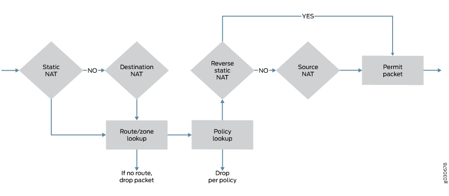
Static NAT and destination NAT rules are processed before route and security policy lookup. Static NAT rules take precedence over destination NAT rules. Reverse mapping of static NAT rules takes place after route and security policy lookup and takes precedence over source NAT rules. Source NAT rules are processed after route and security policy lookup and after reverses mapping of static NAT rules.
The configuration of rules and rule sets is basically the same for each type of NAT—source, destination, or static. But because both destination and static NAT are processed before route lookup, you cannot specify the destination zone, interface or routing instance in the rule set.
NAT Rule Capacity
The restriction on the number of rules per rule set is a device-wide limitation on how many rules a device can support. This restriction helps you better plan and configure the NAT rules for the device.
Available memory might not support the combined maximum number of source NAT rules or rule sets, destination NAT rules or rule sets, and static NAT rules or rule sets.
The NAT rule capacity requirement depends on the SRX Series Firewall and the Junos OS release.
Use Feature Explorer to confirm platform and release support for specific features. Additional platforms may be supported.
Configure NAT Using the NAT Wizard
You can use the NAT Wizard to perform basic NAT configuration. To perform more advanced configuration, use the J-Web interface or the CLI.
To configure NAT using the NAT Wizard:
-
Select
Configure > Tasks > Configure NATin the J-Web interface. - Click the Launch NAT Wizard button.
- Follow the wizard prompts.
The upper-left area of the wizard page shows where you are in the configuration process. The lower-left area of the page shows field-sensitive help. When you click a link under the Resources heading, the document opens in your browser. If the document opens in a new tab, be sure to close only the tab (not the browser window) when you close the document.
Example: Configure NAT for Multiple ISPs
This example shows how to configure a Juniper Networks device for address translation of multiple ISPs.
Requirements
Before you begin:
Configure network interfaces on the device. See Interfaces User Guide for Security Devices.
Create security zones and assign interfaces. See Understanding Security Zones.
Overview
In this example, you can configure an SRX Series Firewall by connecting the LAN to the Internet by using NAT feature through two ISP connections. In this configuration, the trust zone contains the private address space, and the two untrust zones contain the public address space. The configuration connects the LAN to the two ISPs and supports traffic in both directions. The example is a combination of source NAT rules to connect to Internet from the LAN, and destination and static NAT rules to connect to the LAN from Internet.
Configuration
Configure NAT for Multiple ISPs
CLI Quick Configuration
commit from configuration mode.set routing-instances isp1 instance-type virtual-router set routing-instances isp1 interface ge-0/0/2.0 set routing-instances isp1 routing-options static route 10.0.0.0/8 next-table inet.0 set routing-instances isp1 routing-options static route 0.0.0.0/0 next-hop 192.0.2.20 set routing-instances isp2 instance-type virtual-router set routing-instances isp2 interface ge-0/0/3.0 set routing-instances isp2 routing-options static route 10.0.0.0/8 next-table inet.0 set routing-instances isp2 routing-options static route 0.0.0.0/0 next-hop 198.51.100.251 set routing-options interface-routes rib-group inet isp set routing-options static route 10.0.0.0/8 next-hop 10.0.21.254 set routing-options rib-groups isp import-rib inet.0 set routing-options rib-groups isp import-rib isp1.inet.0 set routing-options rib-groups isp import-rib isp2.inet.0 set security policies from-zone trust to-zone untrust1 policy tr-untr1-pol match source-address any set security policies from-zone trust to-zone untrust1 policy tr-untr1-pol match destination-address any set security policies from-zone trust to-zone untrust1 policy tr-untr1-pol match application any set security policies from-zone trust to-zone untrust1 policy tr-untr1-pol then permit set security policies from-zone trust to-zone untrust2 policy tr-untr2-pol match source-address any set security policies from-zone trust to-zone untrust2 policy tr-untr2-pol match destination-address any set security policies from-zone trust to-zone untrust2 policy tr-untr2-pol match application any set security policies from-zone trust to-zone untrust2 policy tr-untr2-pol then permit set security policies from-zone untrust1 to-zone untrust2 policy untr1-untr2-pol match source-address any set security policies from-zone untrust1 to-zone untrust2 policy untr1-untr2-pol match destination-address any set security policies from-zone untrust1 to-zone untrust2 policy untr1-untr2-pol match application any set security policies from-zone untrust1 to-zone untrust2 policy untr1-untr2-pol then reject set security policies from-zone untrust2 to-zone untrust1 policy untr2-untr1-pol match source-address any set security policies from-zone untrust2 to-zone untrust1 policy untr2-untr1-pol match destination-address any set security policies from-zone untrust2 to-zone untrust1 policy untr2-untr1-pol match application any set security policies from-zone untrust2 to-zone untrust1 policy untr2-untr1-pol then reject set security policies from-zone untrust1 to-zone trust policy untr1-tr-pol match source-address any set security policies from-zone untrust1 to-zone trust policy untr1-tr-pol match destination-address ftp-ser set security policies from-zone untrust1 to-zone trust policy untr1-tr-pol match destination-address telnet-ser set security policies from-zone untrust1 to-zone trust policy untr1-tr-pol match application junos-ftp set security policies from-zone untrust1 to-zone trust policy untr1-tr-pol match application junos-telnet set security policies from-zone untrust1 to-zone trust policy untr1-tr-pol then permit set security policies from-zone untrust2 to-zone trust policy untr2-tr-pol match source-address any set security policies from-zone untrust2 to-zone trust policy untr2-tr-pol match destination-address 10.171.9.23/32 set security policies from-zone untrust2 to-zone trust policy untr2-tr-pol match destination-address http-ser set security policies from-zone untrust2 to-zone trust policy untr2-tr-pol match destination-address 10.103.12.0/24 set security policies from-zone untrust2 to-zone trust policy untr2-tr-pol match application junos-http set security policies from-zone untrust2 to-zone trust policy untr2-tr-pol match application junos-icmp-all set security policies from-zone untrust2 to-zone trust policy untr2-tr-pol match application junos-dhcp-server set security policies from-zone untrust2 to-zone trust policy untr2-tr-pol then permit set security nat source pool pool_1 address 192.0.2.40/32 to 192.0.2.190/32 set security nat source pool pool_2 address 192.0.2.250/32 set security nat source pool pool_3 address 198.51.100.20/32 to 198.51.100.30/32 set security nat source address-persistent set security nat source pool-utilization-alarm raise-threshold 90 set security nat source pool-utilization-alarm clear-threshold 80 set security nat source rule-set SR_SET_1 from zone trust set security nat source rule-set SR_SET_1 to zone untrust1 set security nat source rule-set SR_SET_1 rule rule1 match source-address 10.11.0.0/16 set security nat source rule-set SR_SET_1 rule rule1 match source-address 10.147.0.0/16 set security nat source rule-set SR_SET_1 rule rule1 match destination-address 0.0.0.0/0 set security nat source rule-set SR_SET_1 rule rule1 then source-nat pool pool_1 set security nat source rule-set SR_SET_1 rule rule2 match source-address 10.148.1.0/27 set security nat source rule-set SR_SET_1 rule rule2 match destination-address 0.0.0.0/0 set security nat source rule-set SR_SET_1 rule rule2 then source-nat interface set security nat source rule-set SR_SET_2 from zone trust set security nat source rule-set SR_SET_2 to zone untrust2 set security nat source rule-set SR_SET_2 rule rule3 match source-address 10.140.21.0/27 set security nat source rule-set SR_SET_2 rule rule3 then source-nat pool pool_3 set security nat source rule-set SR_SET_2 rule rule4 match source-address 10.150.45.0/24 set security nat source rule-set SR_SET_2 rule rule4 then source-nat off set security nat destination pool dppol_1 address 10.101.1.10/32 set security nat destination pool dppol_1 address port 21 set security nat destination pool dppol_2 address 10.101.1.11/32 set security nat destination pool dppol_2 address port 2101 set security nat destination pool dppol_3 address 10.103.12.251/32 set security nat destination pool dppol_3 address port 23 set security nat destination pool dppol_4 address 10.103.12.241/32 set security nat destination pool dppol_4 address port 23 set security nat destination pool dppol_5 address 10.103.1.11/32 set security nat destination pool dppol_5 address port 22 set security nat destination rule-set DR_SET1 from routing-instance isp1 set security nat destination rule-set DR_SET1 rule rule1 match destination-address 192.168.0.10/32 set security nat destination rule-set DR_SET1 rule rule1 match destination-port 7230 set security nat destination rule-set DR_SET1 rule rule1 then destination-nat pool dppol_1 set security nat destination rule-set DR_SET1 rule rule2 match destination-address 192.168.1.0/24 set security nat destination rule-set DR_SET1 rule rule2 then destination-nat pool dppol_2 set security nat destination rule-set DR_SET2 from routing-instance isp2 set security nat destination rule-set DR_SET2 rule rule3 match destination-address 192.168.2.2/32 set security nat destination rule-set DR_SET2 rule rule3 match destination-port 7351 set security nat destination rule-set DR_SET2 rule rule3 then destination-nat pool dppol_3 set security nat destination rule-set DR_SET2 rule rule4 match destination-address 192.168.4.171/32 set security nat destination rule-set DR_SET2 rule rule4 match destination-port 3451 set security nat destination rule-set DR_SET2 rule rule4 then destination-nat pool dppol_4 set security nat static rule-set ST_SET1 from zone trust set security nat static rule-set ST_SET1 rule rule1 match destination-address 10.0.10.0/24 set security nat static rule-set ST_SET1 rule rule1 then static-nat prefix 192.168.5.0/24 set security nat static rule-set ST_SET2 from routing-instance isp1 set security nat static rule-set ST_SET2 rule rule2 match destination-address 192.168.6.0/24 set security nat static rule-set ST_SET2 rule rule2 then static-nat prefix 10.107.30.0/24 set security nat static rule-set ST_SET2 rule rule3 match destination-address 192.168.0.10/32 set security nat static rule-set ST_SET2 rule rule3 then static-nat prefix 10.171.9.23/32
Step-by-Step Procedure
The following example requires you to navigate various levels in the configuration hierarchy. For instructions on how to do that, see Using the CLI Editor in Configuration Mode in the Junos OS CLI User Guide.
Configure routing instances.
[edit ]
user@host# set routing-instances isp1 instance-type virtual-router
user@host# set routing-instances isp1 interface ge-0/0/2.0
user@host# set routing-instances isp1 routing-options static route 10.0.0.0/8 next-table inet.0
user@host# set routing-instances isp1 routing-options static route 0.0.0.0/0 next-hop 192.0.2.20
user@host# set routing-instances isp2 instance-type virtual-router
user@host# set routing-instances isp2 interface ge-0/0/3.0
user@host# set routing-instances isp2 routing-options static route 10.0.0.0/8 next-table inet.0
user@host# set routing-instances isp2 routing-options static route 0.0.0.0/0 next-hop 198.51.100.251
Configure rib groups and routing options.
[edit ]
user@host# set routing-options interface-routes rib-group inet isp
user@host# set routing-options static route 10.0.0.0/8 next-hop 10.0.21.254
user@host# set routing-options rib-groups isp import-rib inet.0
user@host# set routing-options rib-groups isp import-rib isp1.inet.0
user@host# set routing-options rib-groups isp import-rib isp2.inet.0
Configure security policies.
[edit security policies]
user@host# set from-zone trust to-zone untrust1 policy tr-untr1-pol match source-address any
user@host# set from-zone trust to-zone untrust1 policy tr-untr1-pol match destination-address any
user@host# set from-zone trust to-zone untrust1 policy tr-untr1-pol match application any
user@host# set from-zone trust to-zone untrust1 policy tr-untr1-pol then permit
user@host# set from-zone trust to-zone untrust2 policy tr-untr2-pol match source-address any
user@host# set from-zone trust to-zone untrust2 policy tr-untr2-pol match destination-address any
user@host# set from-zone trust to-zone untrust2 policy tr-untr2-pol match application any
user@host# set from-zone trust to-zone untrust2 policy tr-untr2-pol then permit
user@host# set from-zone untrust1 to-zone untrust2 policy untr1-untr2-pol match source-address any
user@host# set from-zone untrust1 to-zone untrust2 policy untr1-untr2-pol match destination-address anyfrom-zone untrust1 to-zone untrust2 policy untr1-untr2-pol match destination-address any
user@host# set from-zone untrust1 to-zone untrust2 policy untr1-untr2-pol match application any
user@host# set from-zone untrust1 to-zone untrust2 policy untr1-untr2-pol then reject
user@host# set from-zone untrust2 to-zone untrust1 policy untr2-untr1-pol match source-address any
user@host# set from-zone untrust2 to-zone untrust1 policy untr2-untr1-pol match destination-address any
user@host# set from-zone untrust2 to-zone untrust1 policy untr2-untr1-pol match application any
user@host# set from-zone untrust2 to-zone untrust1 policy untr2-untr1-pol then reject
user@host# set from-zone untrust1 to-zone trust policy untr1-tr-pol match source-address any
user@host# set from-zone untrust1 to-zone trust policy untr1-tr-pol match destination-address ftp-ser
user@host# set from-zone untrust1 to-zone trust policy untr1-tr-pol match destination-address telnet-ser
user@host# set from-zone untrust1 to-zone trust policy untr1-tr-pol match application junos-ftp
user@host# set from-zone untrust1 to-zone trust policy untr1-tr-pol match application junos-telnet
user@host# set from-zone untrust1 to-zone trust policy untr1-tr-pol then permit
user@host# set from-zone untrust2 to-zone trust policy untr2-tr-pol match source-address any
user@host# set from-zone untrust2 to-zone trust policy untr2-tr-pol match destination-address 10.171.9.23/32
user@host# set from-zone untrust2 to-zone trust policy untr2-tr-pol match destination-address http-ser
user@host# set from-zone untrust2 to-zone trust policy untr2-tr-pol match destination-address 10.103.12.0/24
user@host# set from-zone untrust2 to-zone trust policy untr2-tr-pol match application junos-http
user@host# set from-zone untrust2 to-zone trust policy untr2-tr-pol match application junos-icmp-all
user@host# set from-zone untrust2 to-zone trust policy untr2-tr-pol match application junos-dhcp-server
user@host# set from-zone untrust2 to-zone trust policy untr2-tr-pol then permit
Configure source NAT pools and rules.
[edit security nat]
user@host# set source pool pool_1 address 192.0.2.40/32 to 192.0.2.190/32
user@host# set source pool pool_2 address 192.0.2.250/32
user@host# set source pool pool_3 address 198.51.100.20/32 to 198.51.100.30/32
user@host# set source address-persistent
user@host# set source pool-utilization-alarm raise-threshold 90
user@host# set source pool-utilization-alarm clear-threshold 80
user@host# set source rule-set SR_SET_1 from zone trust
user@host# set source rule-set SR_SET_1 to zone untrust1
user@host# set source rule-set SR_SET_1 rule rule1 match source-address 10.11.0.0/16
user@host# set source rule-set SR_SET_1 rule rule1 match source-address 10.147.0.0/16
user@host# set source rule-set SR_SET_1 rule rule1 match destination-address 0.0.0.0/0
user@host# set source rule-set SR_SET_1 rule rule1 then source-nat pool pool_1
user@host# set source rule-set SR_SET_1 rule rule2 match source-address 10.148.1.0/27
user@host# set source rule-set SR_SET_1 rule rule2 match destination-address 0.0.0.0/0
user@host# set source rule-set SR_SET_1 rule rule2 then source-nat interface
user@host# set source rule-set SR_SET_2 from zone trust
user@host# set source rule-set SR_SET_2 to zone untrust2
user@host# set source rule-set SR_SET_2 rule rule3 match source-address 10.140.21.0/27
user@host# set source rule-set SR_SET_2 rule rule3 then source-nat pool pool_3
user@host# set source rule-set SR_SET_2 rule rule4 match source-address 10.150.45.0/24
user@host# set source rule-set SR_SET_2 rule rule4 then source-nat off
Configure destination NAT pools and rules.
[edit security nat]
user@host#set destination pool dppol_1 address 10.101.1.10/32
user@host#set destination pool dppol_1 address port 21
user@host#set destination pool dppol_2 address 10.101.1.11/32
user@host#set destination pool dppol_2 address port 2101
user@host#set destination pool dppol_3 address 10.103.12.251/32
user@host#set destination pool dppol_3 address port 23
user@host#set destination pool dppol_4 address 10.103.12.241/32
user@host#set destination pool dppol_4 address port 23
user@host#set destination pool dppol_5 address 10.103.1.11/32
user@host#set destination pool dppol_5 address port 22
user@host#set destination rule-set DR_SET1 from routing-instance isp1
user@host#set destination rule-set DR_SET1 rule rule1 match destination-address 192.168.0.10/32
user@host#set destination rule-set DR_SET1 rule rule1 match destination-port 7230
user@host#set destination rule-set DR_SET1 rule rule1 then destination-nat pool dppol_1
user@host#set destination rule-set DR_SET1 rule rule2 match destination-address 192.168.1.0/24
user@host#set destination rule-set DR_SET1 rule rule2 then destination-nat pool dppol_2
user@host#set destination rule-set DR_SET2 from routing-instance isp2
user@host#set destination rule-set DR_SET2 rule rule3 match destination-address 192.168.2.2/32
user@host#set destination rule-set DR_SET2 rule rule3 match destination-port 7351
user@host#set destination rule-set DR_SET2 rule rule3 then destination-nat pool dppol_3
user@host#set destination rule-set DR_SET2 rule rule4 match destination-address 192.168.4.171/32
user@host#set destination rule-set DR_SET2 rule rule4 match destination-port 3451
user@host#set destination rule-set DR_SET2 rule rule4 then destination-nat pool dppol_4
Configure static NAT rules.
[edit security nat]
user@host#set static rule-set ST_SET1 from zone trust
user@host#set static rule-set ST_SET1 rule rule1 match destination-address 10.0.10.0/24
user@host#set static rule-set ST_SET1 rule rule1 then static-nat prefix 192.168.5.0/24
user@host#set static rule-set ST_SET2 from routing-instance isp1
user@host#set static rule-set ST_SET2 rule rule2 match destination-address 192.168.6.0/24
user@host#set static rule-set ST_SET2 rule rule2 then static-nat prefix 10.107.30.0/24
user@host#set static rule-set ST_SET2 rule rule3 match destination-address 192.168.7.2/32
user@host#set static rule-set ST_SET2 rule rule3 then static-nat prefix 10.171.9.23/32
Results
From configuration mode, confirm your configuration by entering the show configuration command. If the output does not display the intended configuration, repeat the configuration instructions in this example to correct it.
user@host# show configuration routing-instances
    routing-instances {
        isp1 {
            instance-type virtual-router;
            interface ge-0/0/2.0;
            routing-options {
                static {
                    route 10.0.0.0/8 next-table inet.0;
                    route 0.0.0.0/0 next-hop 192.0.2.20;
                }
            }
        }
        isp2 {
            instance-type virtual-router;
            interface ge-0/0/3.0;
            routing-options {
                static {
                    route 10.0.0.0/8 next-table inet.0;
                    route 0.0.0.0/0 next-hop 198.51.100.251;
                }
            }
        }
    }
user@host# show configuration routing-options
routing-options {
    interface-routes {
        rib-group inet isp;
    }
    static {
        route 10.0.0.0/8 next-hop 10.0.21.254;
    }
    rib-groups {
        isp {
            import-rib [ isp1.inet.0 isp2.inet.0 ];
        }
    }
}
user@host# show configuration policies
policies {
    from-zone trust to-zone untrust1 {
        policy tr-untr1-pol {
            match {
                source-address any;
                destination-address any;
                application any;
            }
            then {
                permit;
            }
        }
    }
    from-zone trust to-zone untrust2 {
        policy tr-untr2-pol {
            match {
                source-address any;
                destination-address any;
                application any;
            }
            then {
                permit;
            }
        }
    }
    from-zone untrust1 to-zone untrust2 {
        policy untr1-untr2-pol {
            match {
                source-address any;
                destination-address any;
                application any;
            }
            then {
                reject;
            }
        }
    }
    from-zone untrust2 to-zone untrust1 {
        policy untr2-untr1-pol {
            match {
                source-address any;
                destination-address any;
                application any;
            }
            then {
                reject;
            }
        }
    }
    from-zone untrust1 to-zone trust {
        policy untr1-tr-pol {
            match {
                source-address any;
                destination-address [ ftp-ser telnet-ser ];
                application [ junos-ftp junos-telnet ];
            }
            then {
                permit;
            }
        }
    }
    from-zone untrust2 to-zone trust {
        policy untr2-tr-pol {
            match {
                source-address any;
                destination-address [ 10.171.9.23/32 http-ser 10.103.12.0/24 ];
                application [ junos-http junos-icmp-all junos-dhcp-server ];
            }
            then {
                permit;
            }
        }
    }
}
user@host# show configuration security nat
security {
    nat {
        source {
            pool pool_1 {
                address {
                    192.0.2.40/32 to 192.0.2.190/32;
                }
            }
            pool pool_2 {
                address {
                    192.0.2.250/32;
                }
            }
            pool pool_3 {
                address {
                    198.51.100.20/32 to 198.51.100.30/32;
                }
            }
            address-persistent;
            pool-utilization-alarm raise-threshold 90 clear-threshold 80;
            rule-set SR_SET_1 {
                from zone trust;
                to zone untrust1;
                rule rule1 {
                    match {
                        source-address [ 10.11.0.0/16 10.147.0.0/16 ];
                        destination-address 0.0.0.0/0;
                    }
                    then {
                        source-nat {
                            pool {
                                pool_1;
                            }
                        }
                    }
                }
                rule rule2 {
                    match {
                        source-address 10.148.1.0/27;
                        destination-address 0.0.0.0/0;
                    }
                    then {
                        source-nat {
                            interface;
                        }
                    }
                }
            }
            rule-set SR_SET_2 {
                from zone trust;
                to zone untrust2;
                rule rule3 {
                    match {
                        source-address 10.140.21.0/27;
                    }
                    then {
                        source-nat {
                            pool {
                                pool_3;
                            }
                        }
                    }
                }
                rule rule4 {
                    match {
                        source-address 10.150.45.0/24;
                    }
                    then {
                        source-nat {
                            off;
                        }
                    }
                }
            }
        }
user@host# show configuration security nat
destination {
    pool dppol_1 {
        address 10.101.1.10/32 port 21;
    }
    pool dppol_2 {
        address 10.101.1.11/32 port 2101;
    }
    pool dppol_3 {
        address 10.103.12.251/32 port 23;
    }
    pool dppol_4 {
        address 10.103.12.241/32 port 23;
    }
    pool dppol_5 {
        address 10.103.1.11/32 port 22;
    }
    rule-set DR_SET1 {
        from routing-instance isp1;
        rule rule1 {
            match {
                destination-address 192.168.0.10/32;
                destination-port 7230;
            }
            then {
                destination-nat pool dppol_1;
            }
        }
        rule rule2 {
            match {
                destination-address 192.168.1.0/24;
            }
            then {
                destination-nat pool dppol_2;
            }
        }
    }
    rule-set DR_SET2 {
        from routing-instance isp2;
        rule rule3 {
            match {
                destination-address 192.168.2.2/32;
                destination-port 7351;
            }
            then {
                destination-nat pool dppol_3;
            }
        }
        rule rule4 {
            match {
                destination-address 192.168.4.171/32;
                destination-port 3451;
            }
            then {
                destination-nat pool dppol_4;
            }
        }
    }
}
user@host# show configuration static nat
static {
    rule-set ST_SET1 {
        from zone trust;
        rule rule1 {
            match {
                destination-address 10.0.10.0/24;
            }
            then {
                static-nat prefix 192.168.5.0/24;
            }
        }
    }
    rule-set ST_SET2 {
        from routing-instance isp1;
        rule rule2 {
            match {
                destination-address 192.168.6.0/24;
            }
            then {
                static-nat prefix 10.107.30.0/24;
            }
        }
        rule rule3 {
            match {
                destination-address 192.168.7.2/32;
            }
            then {
                static-nat prefix 10.171.9.23/32;
            }
        }
    }
    }
}
If you are done configuring the device, enter commit from
configuration mode.
Verification
Configure Proxy ARP for NAT (CLI Procedure)
You use NAT proxy ARP functionality to configure proxy ARP entries for IP addresses that require either source or destination NAT and that are in the same subnet as the ingress interface. On SRX Series Firewalls, you must explicitly configure NAT proxy ARP.
When configuring NAT proxy ARP, you must specify the logical interface on which to configure proxy ARP. Then you enter an address or address range.
The device performs proxy ARP for addresses that meet the following conditions:
-
Addresses defined in a static NAT rule or source NAT pool are in the same subnet as the ingress interface.
-
Addresses in the original destination address entry in the destination NAT rules are in the same subnet as the ingress interface.
user@host# set security nat proxy-arp interface ge-0/0/0.0 address 10.1.1.10 to 10.1.1.20
Configure NAT Trace Options
Purpose
The NAT trace options hierarchy configures trace file and flags for verification purposes.
The SRX Series Firewalls have two main components: the Routing Engine and the Packet Forwarding Engine . The Packet Forwarding Engine is divided into the ukernel portion and the real-time portion.
When a NAT configuration is committed, the configuration is first checked and validated on the RE. After validation, the configuration is pushed to the PFE. The configuration is installed on the ukernel PFE, then action is taken on each packet that matches NAT rules on the real-time PFE.
For verification, you can turn on flags individually to debug NAT functionality on the RE, ukernel PFE, or real-time PFE:
-
The
nat-reflag records the trace of the NAT configuration validation on the RE and the configuration push to the PFE. -
The
nat-pfeflag records the trace of the NAT configuration installation on the ukernel PFE. -
The
nat-rtflag records the trace of the NAT rule match, and subsequent action on the real-time PFE.
The trace data is written to /var/log/security-trace by default, and
you can view the data using the command show log security-trace.
If session logging has been enabled in the policy configurations on the device, the session logs will include specific NAT details for each session. See Monitoring Security Policy Statistics for information about how to enable session logging and Information Provided in Session Log Entries for SRX Series Services Gateways for a description of the information provided in session logs.
Action
To verify that NAT configurations are correctly updated to the device upon commit, and that
the NAT rule match and subsequent actions are correct, use the security nat
traceoptions statement.
user@host# set security nat traceoptions flag all
user@host# set security nat traceoptions flag destination-nat-pfe
user@host# set security nat traceoptions flag destination-nat-re
user@host# set security nat traceoptions flag destination-nat-rti
user@host# set security nat traceoptions flag source-nat-pfe
user@host# set security nat traceoptions flag source-nat-re
user@host# set security nat traceoptions flag source-nat-rt
user@host# set security nat traceoptions flag static-nat-pfe
user@host# set security nat traceoptions flag static-nat-re
user@host# set security nat traceoptions flag static-nat-rt
To verify that NAT translations are being applied to the traffic, and to view individual
traffic flow processing with NAT translations, use both the security nat
traceoptions command and the security flow traceoptions command
together. The commands are used together because the NAT
trace, configured using the security nat traceoptions command, is not
recorded unless the flow traceoptions command is also
configured.
To filter a specific flow, you can define a packet filter and use it as a trace option:
user@host# set security flow traceoptions packet-filter packet-filter
user@host# set security flow traceoptions packet-filter packet-filter apply-groups
user@host# set security flow traceoptions packet-filter packet-filter apply-groups-except
user@host# set security flow traceoptions packet-filter packet-filter destination-port
user@host# set security flow traceoptions packet-filter packet-filter destination-prefix
user@host# set security flow traceoptions packet-filter packet-filter interface
user@host# set security flow traceoptions packet-filter packet-filter protocol
user@host# set security flow traceoptions packet-filter packet-filter source-port
user@host# set security flow traceoptions packet-filter packet-filter source-prefix
set security flow traceoptions flag basic-datapath command, as shown in
the following example using a simple packet filter:user@host# set security flow traceoptions file filename user@host# set security flow traceoptions flag basic-datapath user@host# set security flow traceoptions packet-filter client-traffic source-prefixprefix user@host# set security flow traceoptions packet-filter client-traffic destination-prefixprefix user@host# set security nat traceoptions flag all
Monitor NAT Incoming Table Information
Purpose
View NAT table information.
Action
Select Monitor > NAT > Incoming Table in the J-Web UI, or enter the following CLI command:
show security nat incoming-table
Table 1 summarizes the key output fields in the incoming table display.
|
Field |
Values |
|---|---|
| Statistics | |
|
In use |
Number of entries in the NAT table. |
|
Maximum |
Maximum number of entries possible in the NAT table. |
|
Entry allocation failed |
Number of entries failed for allocation. |
| Incoming Table | |
|
Clear |
|
|
Destination |
Destination IP address and port number. |
|
Host |
Host IP address and port number that the destination IP address is mapped to. |
|
References |
Number of sessions referencing the entry. |
|
Timeout |
Timeout, in seconds, of the entry in the NAT tables. |
|
Source-pool |
Name of source pools where translation is allocated. |
Monitor Interface NAT Port Information
Purpose
View port usage for an interface source pool information.
Action
To monitor interface NAT port information, do one of the following:
-
Click Monitor > Firewall/NAT > Interface NAT or Monitor > NAT > Interface NAT Ports in the J-Web UI or enter the CLI command
show security nat
                            interface-nat-ports
.
Table 2 summarizes key output fields in the interface NAT display.
|
Field |
Values |
Additional Information |
|---|---|---|
|
Pool Index |
Port pool index. |
– |
|
Total Ports |
Total number of ports in a port pool. |
– |
|
Single Ports Allocated |
Number of ports allocated one at a time that are in use. |
– |
|
Single Ports Available |
Number of ports allocated one at a time that are free for use. |
– |
|
Twin Ports Allocated |
Number of ports allocated two at a time that are in use. |
– |
|
Twin Ports Available |
Number of ports allocated two at a time that are free for use. |
– |
Additional Platform Information
Use Feature Explorer to confirm platform and release support for specific features. Additional platforms may be supported.
|
NAT Rule Type |
SRX300SRX320 |
SRX340SRX345 |
SRX400 |
SRX440SRX440-2AC |
SRX1500SRX1600 |
SRX2300SRX4120SRX4100SRX4200 |
SRX4600SRX5400SRX5600SRX5800 |
SRX4700 |
|
|---|---|---|---|---|---|---|---|---|---|
|
Source NAT rule |
2048 |
2048 |
1280 | 1536 |
8192 |
20,480 |
30,720 |
51200 |
|
|
Destination NAT rule |
2048 |
2048 |
1280 | 1536 |
8192 |
20,480 |
30,720 |
51200 |
|
|
Static NAT rule |
2048 |
4096 |
1280 | 1536 |
8192 |
20,480 |
30,720 |
51200 |
|
|
Objects |
SRX1600SRX2300SRX4120 |
SRX4600SRX5400SRX5600SRX5800 |
SRX4700 |
|---|---|---|---|
|
Total NAT rule sets per system |
10,000 |
30,720 |
51200 |
|
Total NAT rules per rule set |
10,000 |
30,720 |
51200 |
| Platform | Number of IPs Supported with OL |
|---|---|
| vSRX small VSRX-2CPU-4G | 1 |
| SRX1600 | 2 |
| SRX2300, SRX4120 | 16 |
| SRX4300 | 16 |
| vSRX XL VSRX-17CPU-32G | 64 |
| SRX4700 | 128 |
| SRX5000 line of devices | 128 |
Change History Table
Feature support is determined by the platform and release you are using. Use Feature Explorer to determine if a feature is supported on your platform.