GGSN Overview, Redirection, and Pooling Scenarios in GTP Networks
Learn how GGSN functions within GTP networks, including GGSN redirection, pooling scenarios, SPU session handling, and Junos OS configuration techniques to ensure reliable GTP-C and GTP-U tunnel establishment on SRX Series Firewalls.
The GGSN converts the incoming data traffic coming from the mobile users through the Serving GPRS Support Node (SGSN) and forwards it to the relevant network, and vice versa. The GGSN and the SGSN together form the GPRS support nodes (GSNs).
GGSN Redirection
Junos OS supports General Packet Radio Service (GPRS) tunneling protocol (GTP) traffic and gateway GGSN redirection. A GGSN (X) can send create-pdp-context responses in which it can specify different GGSN IP addresses (GGSN Y and GGSN Z) for GGSN tunneling protocol, control (GTP-C) and GGSN tunneling protocol, user plane (GTP-U) messages. Consequently, the SGSN sends the subsequent GTP-C and GTP-U messages to GGSN Y and GGSN Z, instead of X.
GGSN Pooling Scenarios Overview
The GTP supports different GGSN IP addresses during a tunnel creation procedure. There are two GGSN pooling scenarios that support SGSN roaming.
Understanding GGSN Pooling for Scenario 1
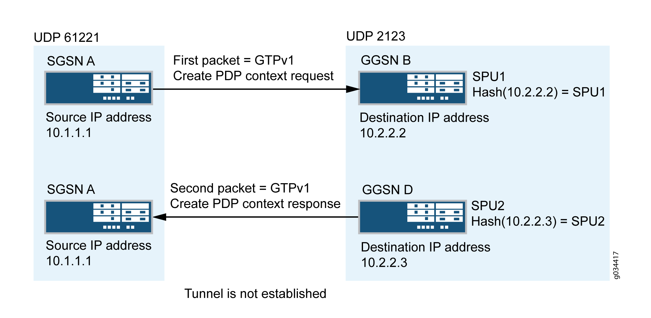
In the below figure, a packet data protocol (PDP) context request is sent from SGSN A to GGSN B during a GTP tunnel creation procedure. After sending the PDP context request message, GGSN D records the request information and it uses a different destination IP address from the request packet’s destination IP address to send the response message to SGSN A.
In this scenario, two GTP packet messages are sent to Services Processing Unit 1 (SPU1) and SPU2 by the central point, and the messages are processed by SPU1 and SPU2 individually. The session is created on SPU1 and SPU 2 for each GTP packet. SPU1 records the request packet information and SPU2 records the response packet information.
The PDP response message sent from GGSN D to SGSN A is dropped because of a lack of request information. Thus the GTP tunnel is not established.
SPU2 cannot retrieve request information from SPU1.
Install Request Information to Remote SPU
In this scenario, the PDP response packet was dropped because of a lack of request information, and the GTP tunnel was not established. This issue can be resolved by installing the request information about the correct SPU.
In the below figure, when creating a tunnel, the response packet's GGSN IP address changes, which triggers a new session and causes the central point to distribute the message to another SPU.
The response packet always returns to the request packet's source address on the corresponding. This helps to install the request information to the remote SPU for the next response packet.
Install the request information into the predictable SPU, HASH (req-src-ip) function while processing the request packet. After the expected SPU number (Hash (10.1.1.1) = SPU2) is calculated based on the source IP address of the PDP request message, the request information is installed on the remote SPU2 through the Juniper Message Passing Interface (JMPI).
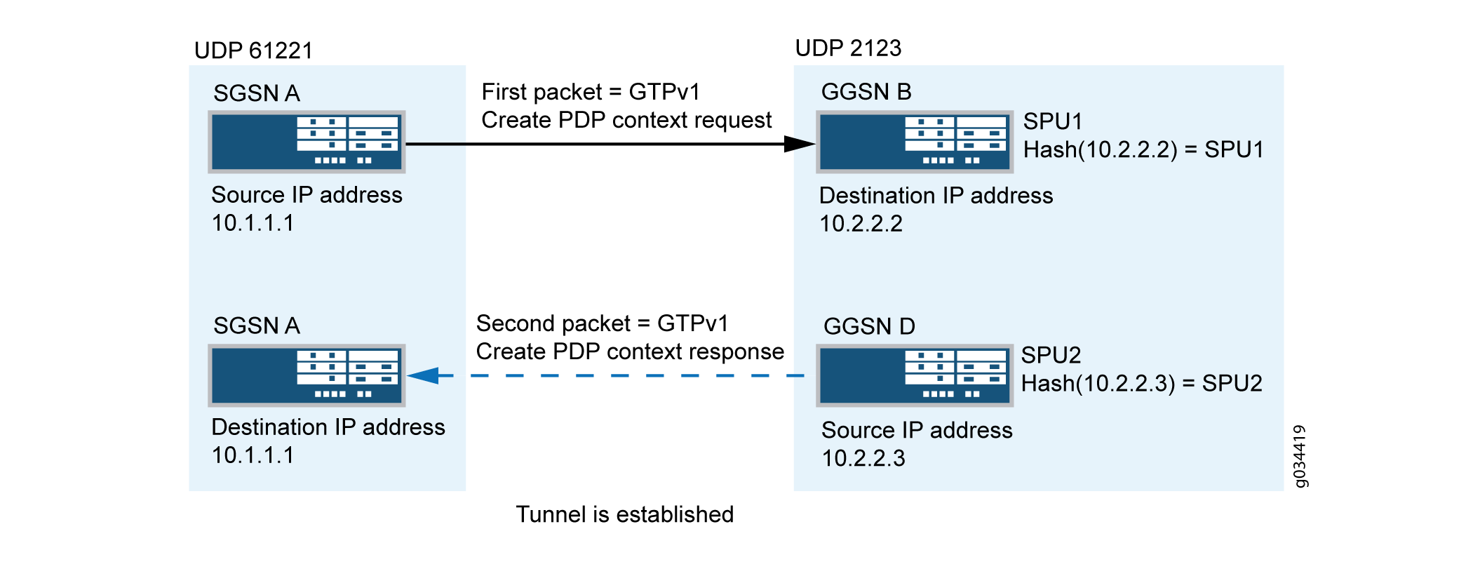
Now the request information is installed on local SPU1 and remote SPU2, so the PDP response message is allowed.
Workarounds for Scenario 1
In scenario 1, the PDP context request message sent from SGSN A reached the Junos
OS default application junos-gprs-gtp and the GTP inspection
was enabled for PDP context request message. However, the PDP context response
message sent from GGSN D cannot reach the Junos OS default application
junos-gprs-gtp. Thus the packet will not be inspected by
the GTP module.
As a workaround, you need to enable GTP inspection for the PDP context response message by configuring the custom policy and applications. Refer to Example: Configuring a GGSN Custom Policy and Application.
Understanding GGSN Pooling for Scenario 2
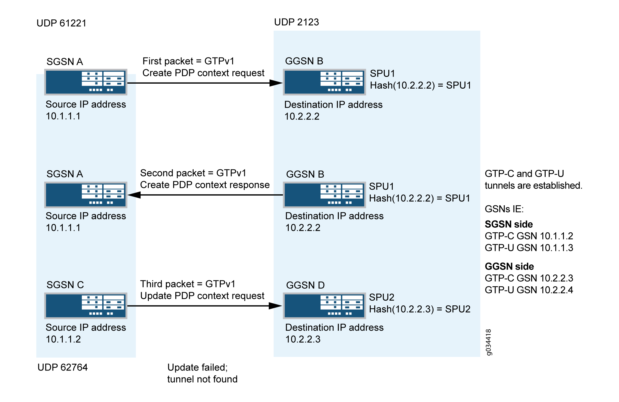
In the below figure, a PDP context request message is sent from SGSN A to GGSN B during a GTP tunnel creation procedure. After receiving the PDP context request message, GGSN B sends the PDP context response message to SGSN A. After receiving the PDP context response message, the GTP-C tunnel is created between SGSN C and GGSN D. Then SGSN C sends an update PDP context request message to GGSN D using different source and destination IP addresses from the request packet's IP header.
In scenario 2, the SGSN A creates the first GTP context request and sends it to the SPU by the central point. The session is created for the request packet on SPU1. The response packet sent from GGSN B to SGSN A reaches the session correctly.
The request packet sent from SGSN A indicates that GTP-C is established on control IP 10.1.1.2 and the GTP-U is established on data IP 10.1.1.3. Likewise, the response message sent from GGSN indicates that GTP-C is established on control IP 10.2.2.3 and GTP-U is established on data IP 10.2.2.4.
The GTP-C and GTP-U tunnels are created on local SPU1 after all the endpoints are established. However, the tunnel is not established on SPU 2, so the PDP update request message received from SPU2 is dropped.
Install Tunnel Information to Remote SPU
In scenario 2, the update request packet is dropped because of a lack of tunnel information. This can be resolved by installing the tunnel information to the correct SPU after the request and response packets are processed. The SPU that receives the response packet installs the tunnel information on the local or remote SPU.
In the below figure, after the tunnel is established, the control messages are sent to the control tunnel endpoint. The destination IP address of all the control messages should be the control tunnel's GGSN endpoint IP address. This helps to calculate the remote SPU number in advance for the subsequent control message.
Install the tunnel information into the predictable SPU. After the SPU number is calculated by the control tunnel GGSN endpoint IP, the tunnel information is installed in the remote SPU through JMPI.
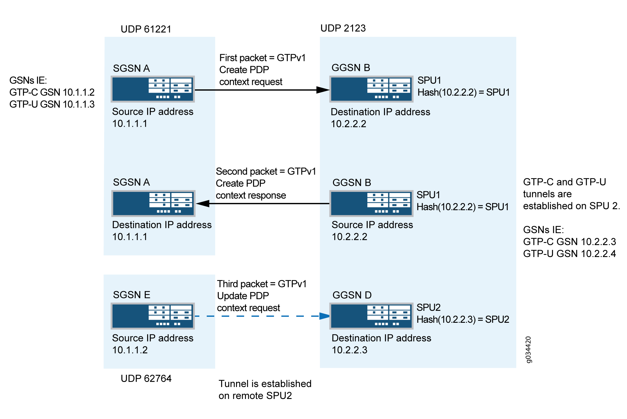
Now the tunnel information is installed on remote SPU2, so the PDP update response message is allowed.
Example: Configure a GGSN Custom Policy and Application
This example shows how to configure a GGSN custom policy and application to support GGSN pooling scenario 1.
Requirements
This example uses the following hardware and software components:
A firewall
A PC
Junos OS Release 12.1X44-D10
Configuration
Configuring a GGSN Custom Policy
Overview
This example shows how to configure Security policies for GTP traffic so that traffic continues to work when GTP Pooling occurs. This example also ensures that GTP traffic flows correctly when the GTP Distribution feature is enabled, with or without GTP inspection. What we do here is configure the security policies in both directions, mirrored. In both directions we use the same address objects and the same applications. Besides the regular GTP application junos-gprs-gtp, we create a custom reverse GTP application, named reverse-junos-gprs-gtp. This reverse GTP application will make GTP packets match the security policy, even when only their source UDP port is a well-known GTP port. This way, all GTP traffic will be matched by the policies and handled correctly as GTP traffic.
CLI Quick Configuration
To quickly configure this example, copy the following commands, paste them into a text file, remove any line breaks, change any details necessary to match your network configuration, copy and paste the commands into the CLI at the [edit] hierarchy level, and then enter commit from configuration mode.
In case when the GTP Distribution feature is used without GTP inspection, do not create the GTP profile and do not apply the application-services gtp-profile to the security policies.
set security address-book global address local_GSN_range 10.1.1.0/24
set security address-book global address remote_GSN_range 10.2.2.0/24
set security gtp profile GTP-Profile
set security policies from-zone trust to-zone untrust policy t-u match source-address local_GSN_range
set security policies from-zone trust to-zone untrust policy t-u match destination-address remote_GSN_range
set security policies from-zone trust to-zone untrust policy t-u match application junos-gprs-gtp
set security policies from-zone trust to-zone untrust policy t-u match application reverse-junos-gprs-gtp
set security policies from-zone trust to-zone untrust policy t-u then permit application-services gtp-profile GTP-Profile
set security policies from-zone untrust to-zone trust policy u-t match source-address remote_GSN_range
set security policies from-zone untrust to-zone trust policy u-t match destination-address local_GSN_range
set security policies from-zone untrust to-zone trust policy u-t match application reverse-junos-gprs-gtp
set security policies from-zone untrust to-zone trust policy u-t match application junos-gprs-gtp
set security policies from-zone untrust to-zone trust policy u-t then permit application-services gtp-profile GTP-Profile
Step-by-Step Procedure
To configure a GGSN custom policy:
Configure the source address.
[edit security] user@host# set security policies from-zone trust to-zone untrust policy t-u match source-address local_GSN_range
Configure the destination address.
[edit security]
user@host#  set security policies from-zone trust to-zone untrust policy t-u match destination-address remote_GSN_range
Configure the policy applications.
[edit security]
user@host#set security policies from-zone trust to-zone untrust policy t-u match application junos-gprs-gtp
user@host#set security policies from-zone trust to-zone untrust policy t-u match application reverse-junos-gprs-gtp
Configure the activity type and specify the GTP profile name.
[edit security]user@host# set security policies from-zone trust to-zone untrust policy t-u then permit application-services gtp-profile GTP-Profile
In case when the GTP Distribution feature is used without GTP inspection:
[edit security] user@host# set security policies from-zone trust to-zone untrust policy t-u then permit
Configure the same again, with the security zones trust and untrust reversed.
Results
From configuration mode, confirm your configuration by entering the show security policies command. If the output does not display the intended configuration, repeat the configuration instructions in this example to correct it.
[edit]
user@host# show security policies
from-zone trust to-zone untrust {
    policy t-u {
        match {
            source-address local_GSN_range;
            destination-address remote_GSN_range;
            application [ junos-gprs-gtp reverse-junos-gprs-gtp ];
        }
        then {
            permit {
                application-services {
                    gtp-profile GTP-Profile;
                }
            }
        }
    }
}
from-zone untrust to-zone trust {
    policy u-t {
        match {
            source-address remote_GSN_range;
            destination-address local_GSN_range;
            application [ reverse-junos-gprs-gtp junos-gprs-gtp ];
        }
        then {
            permit {
                application-services {
                    gtp-profile GTP-Profile;
                }
            }
        }
    }
}
Before we can commit the configuration, we need to configure the reverse GTP application.
Configure Reverse GTP Application
When using the GTP Distribution feature, the flow sessions will be set as uni-directional. This actions to set them as uni-directional is performed by the GTP Application Layer Gateway (ALG) even when not using GTP Inspection. For this reason, it is necessary the GTP ALG be applied to all GTP traffic.
The predefined application junos-gprs-gtp is configured with the GTP ALG. However, in some cases, GTP traffic might not match this application, which will be the case for the return traffic when a different source port is used instead of the standard GTP UDP ports. In that case, the reverse session wing can have a random destination port and the standard GTP port as source port. In order to make sure that the GTP ALG is applied to this reverse GTP traffic in this case, it is necessary to add the following 'reverse' GTP application to all the GTP security policies.
CLI Quick Configuration
To quickly configure this example, copy the following commands, paste them into a text file, remove any line breaks, change any details necessary to match your network configuration, copy and paste the commands into the CLI at the [edit] hierarchy level, and then enter commit from configuration mode.
set applications application reverse-junos-gprs-gtp-c term t1 alg gprs-gtp-c
set applications application reverse-junos-gprs-gtp-c term t1 protocol udp
set applications application reverse-junos-gprs-gtp-c term t1 source-port 2123
set applications application reverse-junos-gprs-gtp-c term t1 destination-port 0-65535
set applications application reverse-junos-gprs-gtp-u term t1 alg gprs-gtp-u
set applications application reverse-junos-gprs-gtp-u term t1 protocol udp
set applications application reverse-junos-gprs-gtp-u term t1 source-port 2152
set applications application reverse-junos-gprs-gtp-u term t1 destination-port 0-65535
set applications application reverse-junos-gprs-gtp-v0 term t1 alg gprs-gtp-v0
set applications application reverse-junos-gprs-gtp-v0 term t1 protocol udp
set applications application reverse-junos-gprs-gtp-v0 term t1 source-port 3386
set applications application reverse-junos-gprs-gtp-v0 term t1 destination-port 0-65535
set applications application-set reverse-junos-gprs-gtp application reverse-junos-gprs-gtp-c
set applications application-set reverse-junos-gprs-gtp application reverse-junos-gprs-gtp-u
set applications application-set reverse-junos-gprs-gtp application reverse-junos-gprs-gtp-v0
Verification
Confirm that the configuration is working properly.
Verify the Configuration
Purpose
Verify that the GGSN custom policy configuration is correct.
Action
Commit the configuration and exit. From operational mode, enter the show security policies command.
Sample Output
command-name
[edit]
user@host# show applications
application reverse-junos-gprs-gtp-c {
    term t1 alg gprs-gtp-c protocol udp source-port 2123 destination-port 0-65535;
}
application reverse-junos-gprs-gtp-u {
    term t1 alg gprs-gtp-u protocol udp source-port 2152 destination-port 0-65535;
}
application reverse-junos-gprs-gtp-v0 {
    term t1 alg gprs-gtp-v0 protocol udp source-port 3386 destination-port 0-65535;
}
application-set reverse-junos-gprs-gtp {
    application reverse-junos-gprs-gtp-c;
    application reverse-junos-gprs-gtp-u;
    application reverse-junos-gprs-gtp-v0;
}

[edit]
user@host# commit and-quit
commit complete
Exiting configuration mode

user@host> show security policies
Default policy: deny-all
Default policy log Profile ID: 0
Pre ID default policy: permit-all
From zone: trust, To zone: untrust
  Policy: t-u, State: enabled, Index: 6, Scope Policy: 0, Sequence number: 1, Log Profile ID: 0
    Source vrf group: any
    Destination vrf group: any
    Source addresses: local_GSN_range
    Destination addresses: remote_GSN_range
    Applications: junos-gprs-gtp, reverse-junos-gprs-gtp
    Source identity feeds: any
    Destination identity feeds: any
    Action: permit, application services
From zone: untrust, To zone: trust
  Policy: u-t, State: enabled, Index: 7, Scope Policy: 0, Sequence number: 1, Log Profile ID: 0
    Source vrf group: any
    Destination vrf group: any
    Source addresses: remote_GSN_range
    Destination addresses: local_GSN_range
    Applications: reverse-junos-gprs-gtp, junos-gprs-gtp
    Source identity feeds: any
    Destination identity feeds: any
    Action: permit, application services
This output shows a summary of policy configuration.