PWHT Modes for EVPN-VPWS Instances
When you terminate an EVPN VPWS-signaled pseudowire on a PS interface, you can use the PS transport logical interface as the VPWS attachment circuit. You can then stitch the resulting point-to-point Ethernet service into another service context, such as an L3VPN routing instance (VRF), a VPLS instance, or an EVPN E-LAN instance, by using PS service logical interfaces.
This model uses VLAN-based demultiplexing on the egress provider edge (PE) router to map
multiple service instances over a single pseudowire. It preserves expected
ethernet-ccc encapsulation behavior for Layer 2 circuit use cases.
You can also use headend termination redundancy modes, such as single pseudowire, active/active multihoming aligned with EVPN designated forwarder (DF) election, or active/standby with deterministic single-forwarder behavior. For active/standby, use a consistent Ethernet Segment Identifier (ESI) assignment on the PS physical interface so VPWS and E-LAN attachments follow the same DF outcome and primary role.
Benefits
-
Enables a single EVPN VPWS-terminated pseudowire to hand off into different service types (VRF, VPLS, or EVPN E-LAN), reducing the need for separate termination designs per service.
-
Supports VLAN-based demultiplexing on the egress PE router so multiple service instances can share a pseudowire while remaining separated by VLAN identifiers.
-
Preserves expected
ethernet-cccencapsulation behavior when PS interfaces are used for VPWS access termination. -
Provides redundancy options (single, active/active, active/standby) to improve service continuity during node or interface failures.
-
Helps keep multihoming role selection consistent across VPWS and E-LAN attachments in active/standby deployments by requiring consistent ESI assignment, reducing the risk of forwarding-role mismatches.
Overview
When you terminate an EVPN VPWS-signaled pseudowire on a PS interface, the PS transport logical interface acts as the EVPN VPWS attachment circuit. The PE router treats the transport unit as the access-facing demarcation for the point-to-point Ethernet service.
You then create one or more PS service logical interfaces on the same PS interface and associate each service unit with the required service context, such as a VRF for L3VPN, a VPLS instance, or an EVPN E-LAN instance. This approach separates pseudowire termination from service handoff: EVPN VPWS provides point-to-point Ethernet connectivity, and the PS service units provide per-service attachment points into the target Layer 2 or Layer 3 forwarding domain.
When you multiplex multiple services over the same EVPN VPWS termination, you use VLAN identifiers to demultiplex traffic on the egress PE router. The EVPN control plane signals a VPWS service, and the data plane uses the VLAN identifier to map traffic to the correct PS service unit and then into the correct VRF, VPLS, or EVPN E-LAN instance.
VLAN selection can also affect multihoming behavior. In EVPN DF election, the Ethernet Tag ID can correspond to the VLAN ID. As a result, the VLAN values used for service separation can influence DF election outcomes on a per-service basis.
With active/standby, you implement deterministic single-forwarder behavior by keeping the standby nonforwarding and transitioning it to active when the primary PE router or PS transport logical interface fails.
Single-wire PWHT
PS interfaces for EVPN-VPWS can be configured as a single-wire implementation. In this
mode, there is no redundancy for the connection. With single-pseudowire termination, you
terminate the VPWS pseudowire on the PS transport unit and stitch it into services without
additional redundancy. As with L2circuit and L2VPN implementations, only
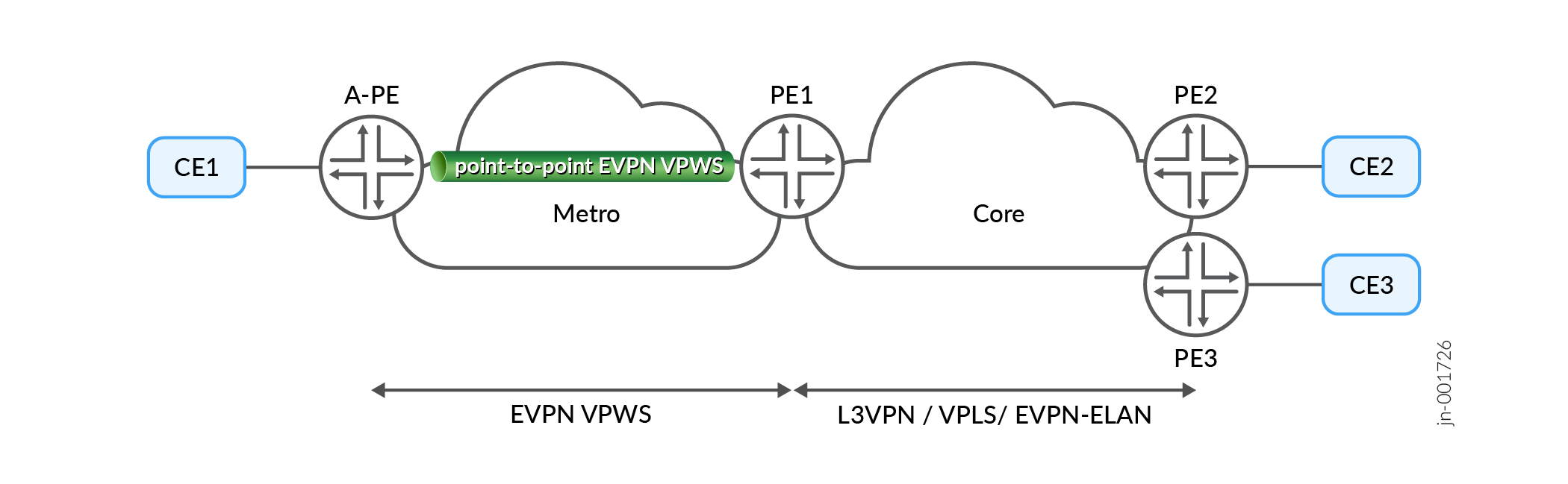
ethernet-ccc encapsulation is supported. Figure 1
shows a single-wire PS implementation with no redundancy.
Active/Active PWHT
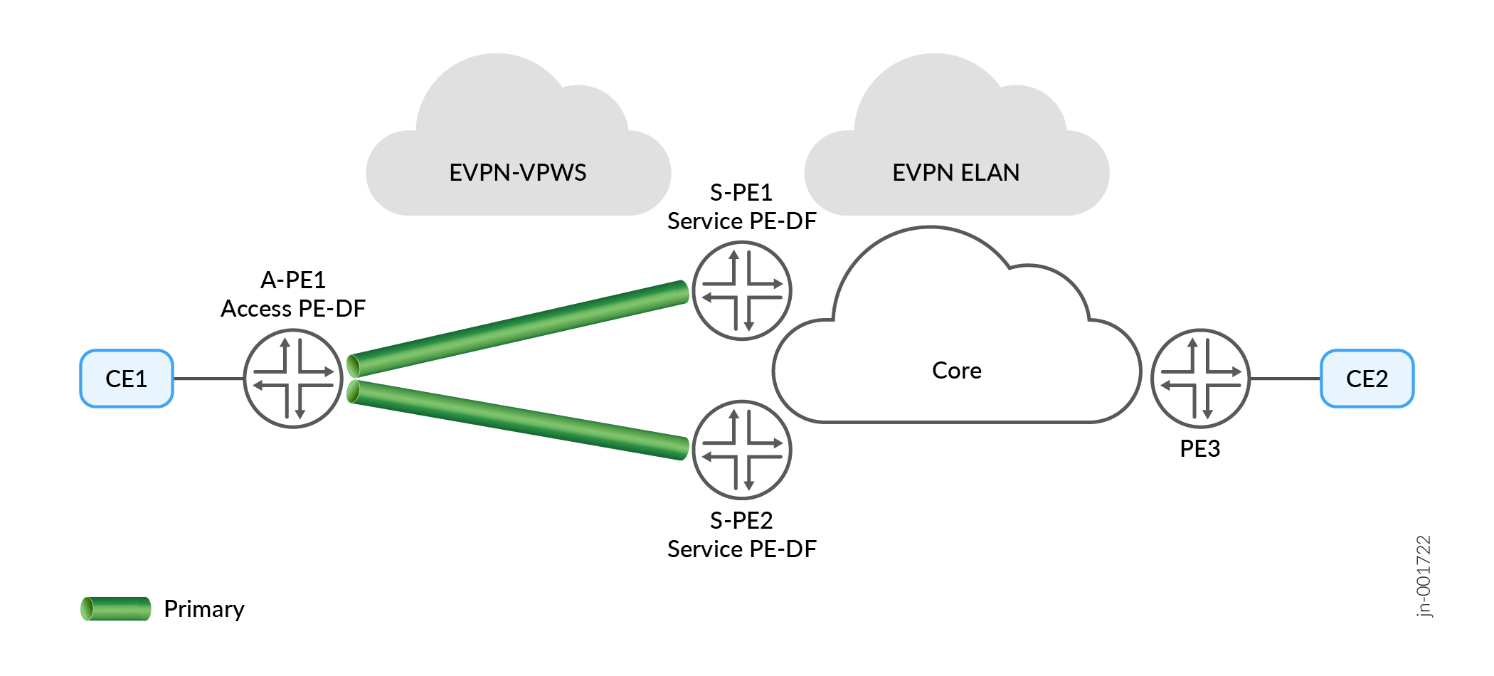
When you add PWHT redundancy for your PS interfaces, you select a forwarding model that determines which PE routers forward traffic and how failover occurs after a node or interface failure. . With active/active, you use redundant pseudowires and rely on EVPN multihoming and DF election so participating PE routers can forward in parallel, subject to DF procedures per VLAN or Ethernet Tag. Figure 2 shows a pseudowire/PWHT configured in active/active mode for redundancy.
Active/Standby PWHT
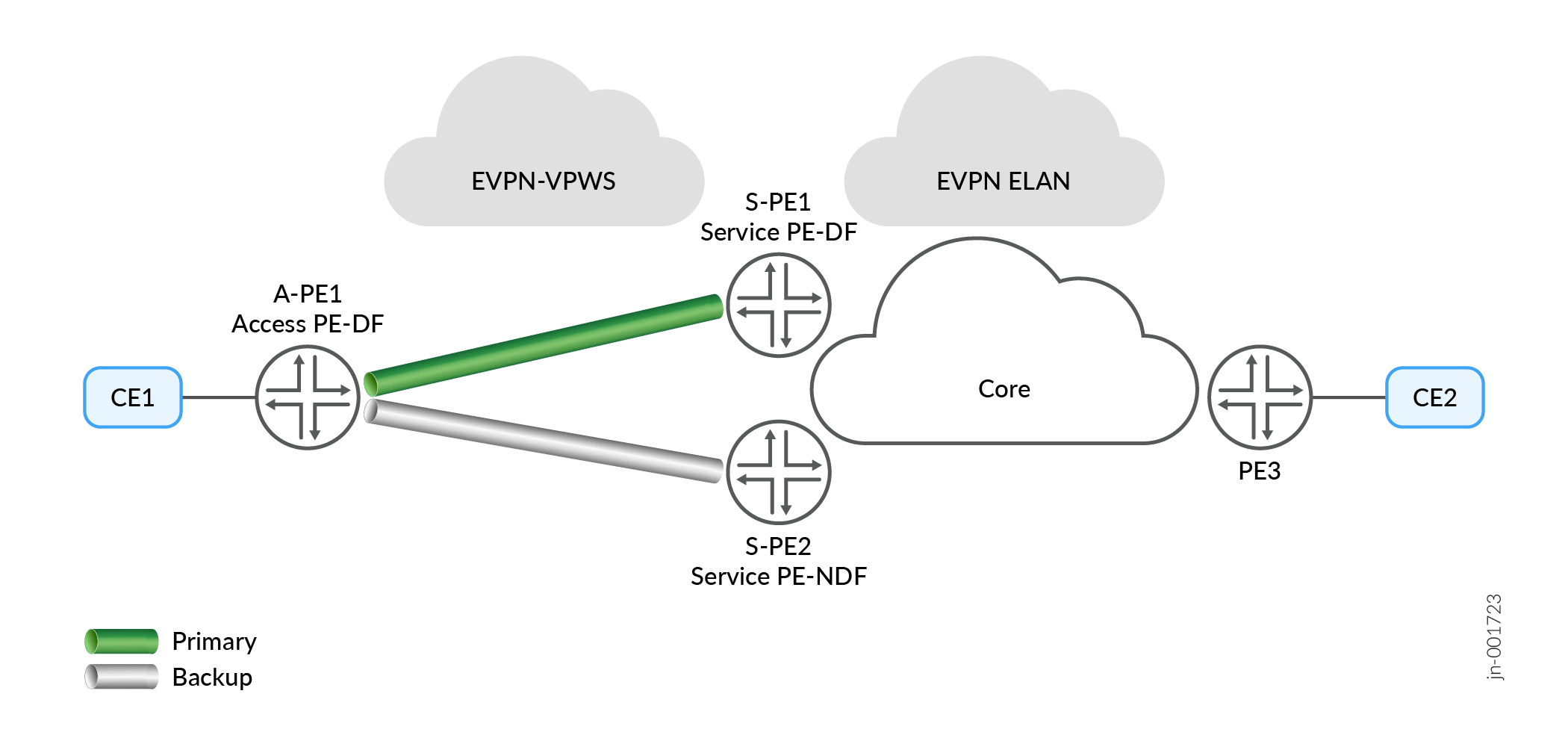
Active/Standby mode allows you to have one PS active, while a second PS interface remains on standby in case the first PS fails. For active/standby, align the EVPN multihoming identity across the VPWS transport attachment and the service-side E-LAN attachment so both sides select the same primary and standby roles. Assign an ESI on the PS physical interface so the PS transport logical interface and the EVPN E-LAN service attachment share the same ESI. This shared ESI supports consistent DF election and helps prevent split-forwarding during steady state and failover. Figure 3 shows a network configured for Active/Standby mode.
Because ESI auto-derivation might not be defined for the PS transport logical interface, treat ESI assignment as an explicit design and configuration requirement. Validate DF role selection against the intended primary and standby behavior for each VLAN or Ethernet Tag.