CTP151 Front Panel and Rear Panel
Figure 1: Front Panel Components
of a CTP151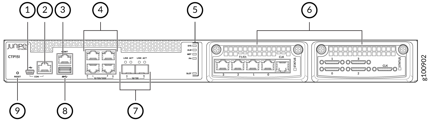
1 — Mini-USB console port | 6 — Interface module slots |
2 — RJ-45 console port | 7 — Two 1-Gigabit Ethernet/10-Gigabit Ethernet SFP+ WAN ports |
3 — One 10/100/1000BASE-T RJ-45 management port | 8 — USB 3.0 port |
4 — Four 10/100/1000BASE-T RJ-45 LAN ports | 9 — Reset button |
5 — System status LEDs |
Note:
The ports that support small form-factor pluggable plus (SFP+) transceivers are not functional in CTPOS 9.1, CTPView 9.1, and earlier releases.
Figure 2: Rear Panel Components
of a CTP151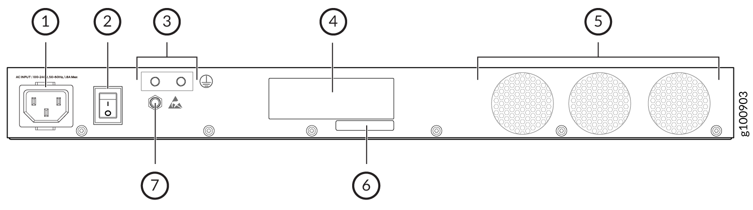
1 — AC power cord inlet | 5 — Fans |
2 — Power switch | 6 — CLEI code |
3 — Grounding points | 7 — Electrostatic discharge (ESD) point |
4 — Serial number |