Create Routing Zone
If your blueprint is using MP-EBGP EVPN overlay control protocol, you can create routing zones. If it's using Pure IP Fabric, you must use the default routing zone. (Overlay control protocol is specified in templates.) You can create one routing zone at a time, or with the help of CSV files, you can create multiple routing zones.
Create Routing Zones (using GUI)
-
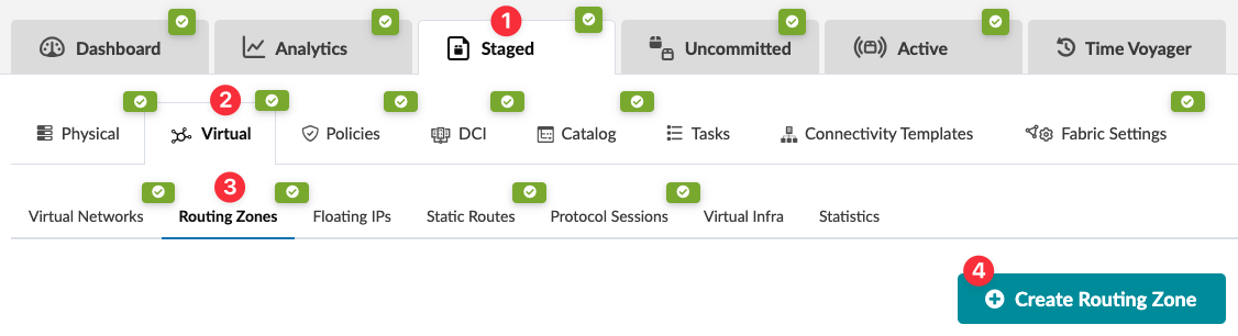
From the blueprint, navigate to Staged > Virtual > Routing
Zones and click Create Routing
Zone.
Next Steps:
Assign resources. Each leaf network device in each routing zone requires a loopback IP address. If IPv6 is enabled on the blueprint, you must also assign IPv6 addresses to the routing zone. After you've assigned connectivity templates to your external generic systems, you'll also need to assign IP addresses.
As of version 5.0.0, assigned loopback IP addresses are included in a new section at the bottom of the routing zone details page called System Loopback Interfaces.
Create Routing Zones (using CSV File)
You can create many routing zones at once with a CSV file. First, you'll export the routing zone schema from your blueprint, then open and populate the file in a spreadsheet program. And finally, you'll import the file back into your blueprint.
-
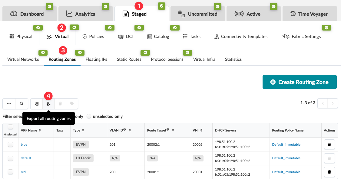
From the blueprint, navigate to Staged > Virtual > Routing
Zones and click the Export all routing
zones button, which is above the table.
-
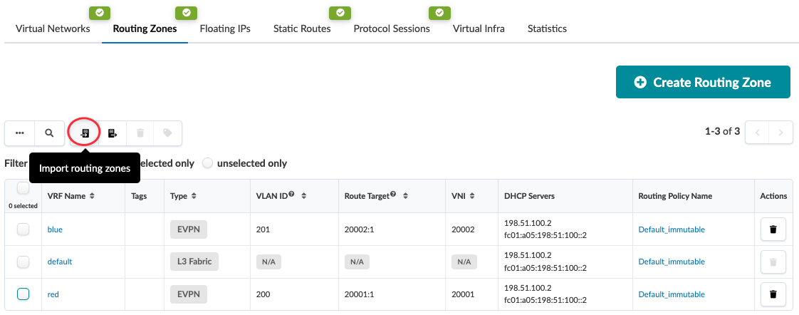
In the HPE Networking Apstra Data Center Director GUI, navigate to
Staged > Virtual > Routing Zones and click
the Import routing zones button, which is above the
table.
Next Steps:
Assign resources. Each leaf network device in each routing zone requires a loopback IP. If IPv6 is enabled on the blueprint, you must also assign IPv6 addresses to the routing zone. After you've assigned connectivity templates to your external generic systems, you'll also need to assign IP addresses.
As of version 5.0.0, assigned loopback IP addresses are included in a new section at the bottom of the routing zone details page called System Loopback Interfaces.