Over the Top or External Gateways
Implementation
You can extend routing zones and virtual networks (VN) to span across HPE Networking Data Center Director-managed blueprints (across pods) or to remote networks (across data centers) that Apstra DC Director doesn't manage. This feature introduces the EVPN Gateway (GW) role, which could be a switch that participates in the fabric or RouteServer(s) on a generic system (tagged as a server) that is connected to the fabric.
EVPN Gateways Use Cases
- Span Layer 3 isolation domains (VRFs / routing zones) to multiple Apstra DC Director-managed pods (blueprints) or extend to remote EVPN domains.
- Provide Layer 2 domain extensions for L2VNI / virtual networks.
- Help extend EVPN domain from Apstra DC Director to Apstra DC Director-managed and Apstra DC Director to unmanaged pods.
- No VXLAN traffic termination on the spine devices - connect external generic systems (tagged as external routers) on spine devices. This is to support IPv4 (underlay) external connectivity. Here spine devices don't need to terminate VXLAN traffic, unlike border leaf devices, when connected to external generic systems (tagged as external routers). In a nutshell, using this can exchange IPv4 routes to remote VTEPs (in the default routing zone/VRF) and only Layer 3 connectivity is required:
Over the Top
When BGP EVPN peering is done "over the top", the Data Center Gateway (DC-GW) is a pure IP transport function and BGP EVPN peering is established between gateways in different data centers.
The next sections describes the procedures for interconnecting two or more BGP-based Ethernet VPN (EVPN) sites in a scalable fashion over an IP network. The motivation is to support extension of EVPN sites without having to rely on typical Data Center Interconnect (DCI) technologies like MPLS/VPLS, which are often difficult to configure, sometimes proprietary, and likely legacy in nature.
"Over the Top" is a simple solution that only requires IP routing between data
centers and an adjusted MTU to support VXLAN encapsulation between gateway
endpoints. In such an implementation, EVPN routes are extended end-to-end via
MP-BGP between sites. Multi-hop BGP is enabled with the assumption that there
will be multiple Layer 3 hops between sites over a WAN. Otherwise the default
TTL decrements to 0 and packets are discarded and don't make it to the remote
router. The needed configuration to address these limitations is automatically
rendered. 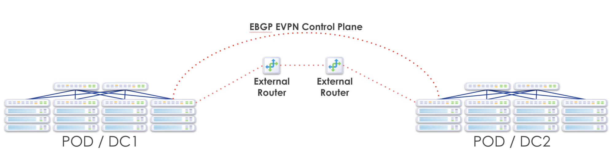
This design merges the separate EVPN-VXLAN domains and VXLAN tunnels between sites. Merging of previously separate EVPN domains in different sites realizes the benefit of extending Layer 2 and Layer 3 (VRF) services between sites, but also renders the sites as a single fault domain. So a failure in one site is necessarily propagated. Also, anytime you stretch Layer 2 across the WAN between sites, you are also extending the flood domain and along with it, all broadcast traffic over your costly WAN links. At this time, this solution does not offer any filtering or QoS.
When separate blueprints manage individual sites (or when only one site is Apstra DC Director-managed) you must create and manage extended routing zones (VRFs) and virtual networks (Layer 2 and/or Layer 3 defined VLANs/subnets) independently in each site. You must manually map VRFs and VNs between sites (creating administrative overhead).
If you’re setting up P2P connections between two data centers (blueprints) in the same controller, each blueprint must pull resources from different IP pools to avoid build errors. To do this, create two IP pools with the same IP subnet, but with different names.
This "Over the Top" solution is the easiest to deploy, requires no additional hardware and introduces no additional WAN config other than increasing the MTU. It is the most flexible and has the lowest barrier to entry. However, the downside is that there is a single EVPN control plane and a routing anomaly in one site will affect convergence and reachability in the other site(s). The extension of Layer 2 flood domains also implies that a broadcast storm in one site extends to the other site(s).
With any DCI implementation, careful resource planning and coordination is required. Adding more sites requires an exponential increase in such planning and coordination. VTEP loopbacks in the underlay need to be leaked. VNIDs must match between sites and in some cases, additional Route Targets (RTs) must be imported. This is covered in detail later in this document.
HPE Networking Apstra Data Center Director Workflow
- Control Plane Extension: EVPN Gateway
- Underlay VTEP Route Advertisements
- Create Remote Over the Top or External Gateways
- Enhanced Routing Zone
- Enhanced Virtual Networks
- Remote Gateway Topology Representation
Control Plane Extension: EVPN Gateway
We use the concept of an an "EVPN Gateway". This device can theoretically be a leaf, spine or superspine fabric node, as well as the DCI device. EVPN Gateways separate the fabric-side from the network that interconnects the sites and masks the site-internal VTEPs.
An EVPN Gateway is a device that belongs to and resides at the edge of an EVPN fabric which is also attached to an external IP network. In an EVPN blueprint, this is always a border-leaf device. The EVPN Gateway of one data center, establishes BGP EVPN peering with a reciprocal EVPN gateway, or gateways, in another data center. The "other" EVPN gateway is the "Remote EVPN Gateway" in Apstra DC Director terminology. The Local EVPN Gateway is assumed to be one of the Apstra DC Director-managed devices in the blueprint, and is selected when creating the "Remote EVPN Gateway". The Local EVPN Gateway will be the border-leaf switch with one or more external routing connections for traffic in and out of the EVPN Clos fabric.
Due to this capability, you can configure a Local EVPN Gateway (always an Apstra DC Director-managed switch) to peer with a non Apstra-managed, or even a non Spine-Leaf device, in another DC. The EVPN Gateway BGP peering is used to carry all EVPN attributes from inside a pod, to outside the pod. In the Apstra DC Director environment, each blueprint represents a data center. If two or more sites are under Apstra DC Director management, you still must configure each site to point to the "Remote EVPN Gateway(s)" in other sites. We recommend that you create multiple, redundant EVPN Gateways for each data center. There is also currently a full mesh requirement between EVPN gateways, although in future releases this requirement will be removed.
Underlay VTEP Route Advertisements
The underlay reachability to VTEP IP addresses, or an equivalent summary route, must be established reciprocally. Each site must advertise these VTEP loopbacks from within the default routing zone into the exported BGP (IPv4) underlay advertisements. Loopbacks in the routing policy are enabled by default.
Create Remote Over the Top or External Gateways
By default, ESI MAC msb (most significant byte) is set to 2 on all blueprints. Every blueprint that's connected must have a unique msb to prevent service-impacting issues. Before creating gateways, change ESI MAC msb accordingly. (You can leave one of them at the default value.)
Remote EVPN Gateway is a logical function that you could instantiate anywhere and on any device. It requires BGP support in general, L2VPN/EVPN AFI/SAFI specifically. To establish a BGP session with an EVPN gateway, IP connectivity, as well as connectivity to TCP port 179 (IANA allocates BGP TCP ports), should be available.
For resilience, we recommend having at least two remote gateways for the same remote EVPN domain.
- From the blueprint, navigate to Staged > DCI > Over the Top
or External Gateways and click Create Over the
Top or External Gateway.
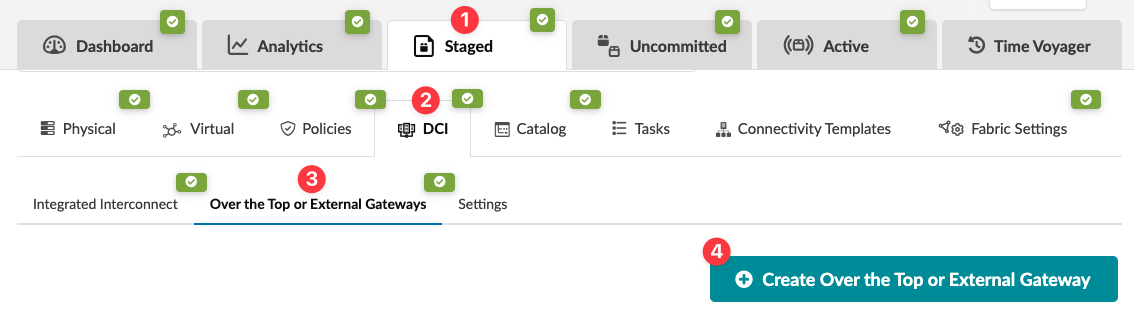
The Create Over the Top or External Gateway dialog opens.
Enter details, as applicable.
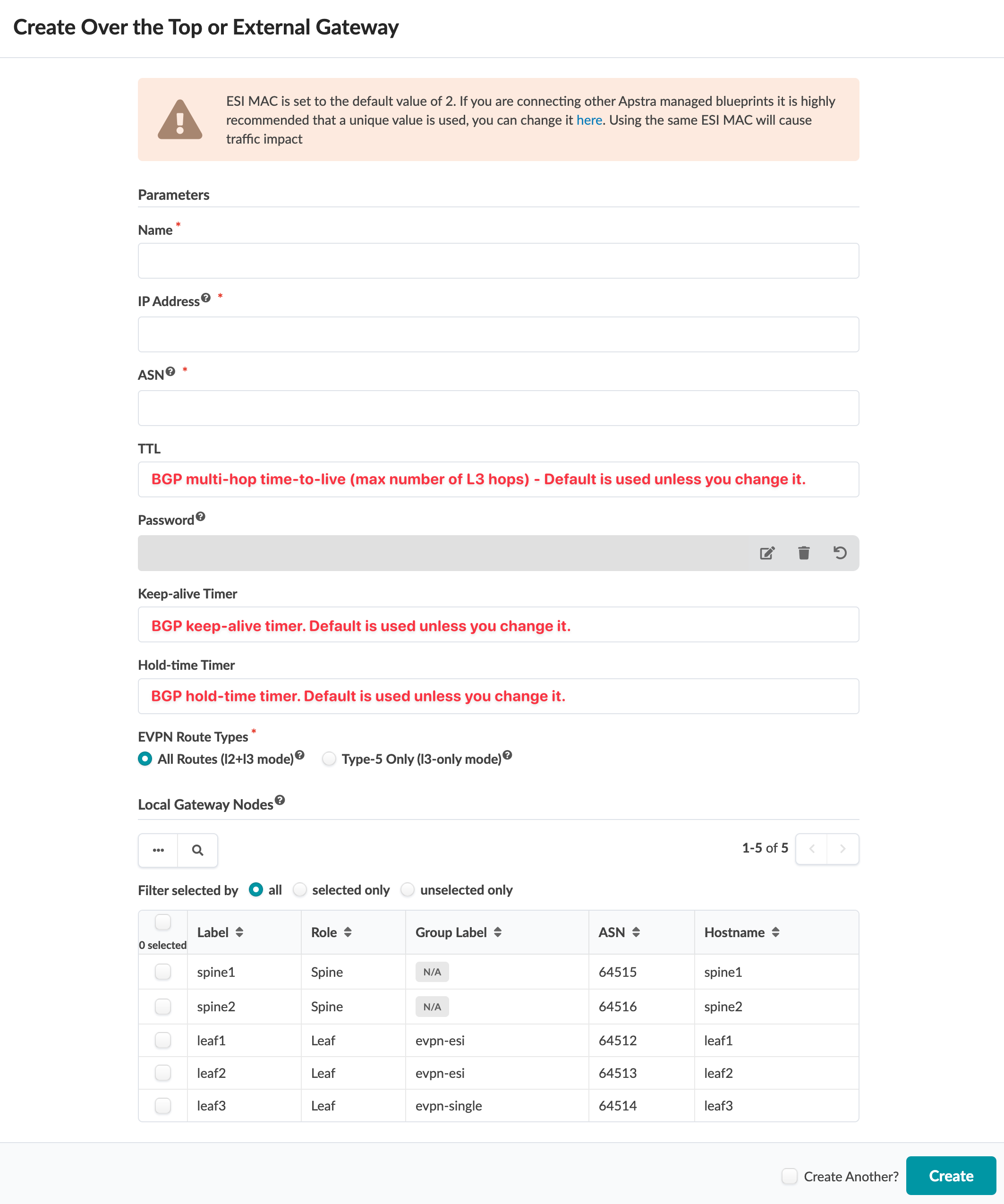
When extending L2 networks between data center fabrics you have the option to exchange only EVPN Route Type RT-5 prefixes (interface-less model). This is useful when there is no need to exchange all host routes between data center locations. This results in smaller requirements for the routing information base (RIB), also known as the routing table, and the forwarding information base (FIB), also known as the forwarding table, on DCI equipment.
Select the Local Gateway Nodes. These are the devices in the blueprint that will be configured with a Local EVPN Gateway. You can select one or more devices to peer with the configured remote EVPN gateway. You can use the query function to help you locate the appropriate nodes. We recommend using multiple border-leaf devices which have direct connections to external generic systems (tagged as external routers).
- Click Create to stage the gateway and return to the table view.
- When you are ready to deploy the devices in the blueprint, commit your changes.
We recommend using multiple remote EVPN gateways. To configure additional remote EVPN gateways, repeat the steps above.
If you are configuring the Remote EVPN Gateway(s) to another blueprint, you must configure and deploy the remote EVPN gateway(s) separately in that blueprint.
Once the change is deployed, the BGP session for the remote EVPN gateways is monitored automatically. To see any anomalies from the blueprint, navigate to Active > Anomalies.
Enhanced Routing Zone
RT (route-target) import/export policies on devices that are part of extended service govern EVPN route installation. Specify route target policies to add import and export route-targets that are used for routing zones/VRFs. You do this when you create routing zones. Navigate to Staged > Virtual > Routing Zones and click Create Routing Zone. For more information, see Routing Zones.
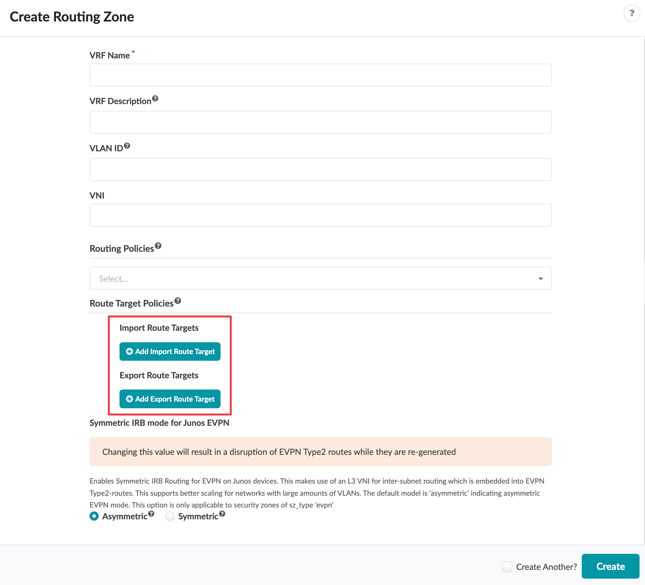
The generated default route-target for routing zones is <L3 VNI>:1. You can't change this default value.
To confirm that correct routes are received at VTEP make sure L3VNIs and route target are identical between the blueprint and remote EVPN domains.
Enhanced Virtual Networks
You can add additional import and export route-targets to be used for virtual networks.
The default route target for virtual networks that is generated is <L2 VNI>:1. You can’t alter this.
For Intra-VNI communication L2VNI specific RT is used. The import RT is used to determine which received routes are applicable to a particular VNI. To establish connectivity, Layer 2 VNIs must be the same between the blueprint and the remote domains. SVI subnets must be identical across domains.
Remote Gateway Topology Representation
Remote EVPN gateways are represented on the topology view as cloud elements with
dotted line connections to the blueprint elements with which BGP sessions are
established as shown in the image below. (Image below is slightly different from
more recent versions.) 