Change Interface IP Address

You may need to change the interface IP address after it's been assigned. You can change it from the associated routing zone.

From Main Interfaces Table

  1. From the blueprint, navigate to Staged > Physical > Interfaces.
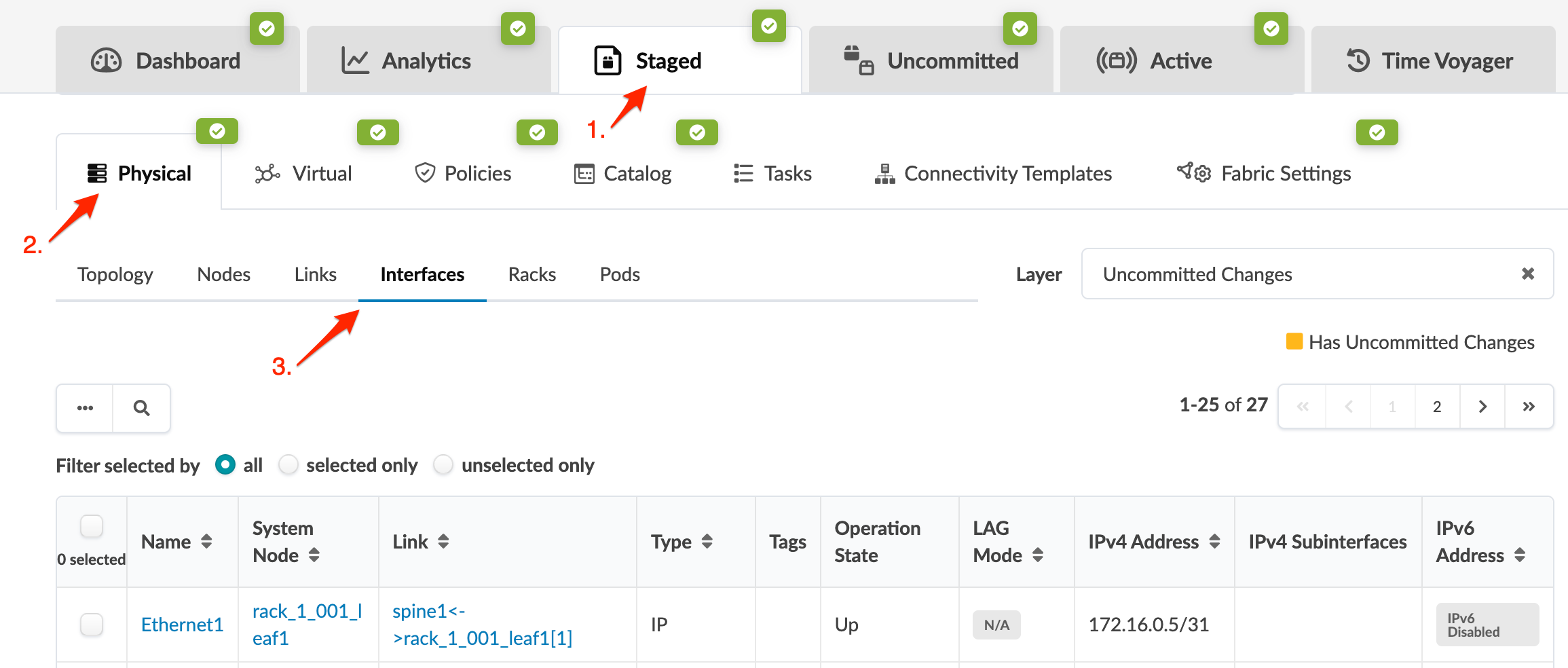
    User interface of a network management tool showing "Staged" tab with "Physical" section and "Interfaces" sub-tab active. Data table lists network interfaces with details like name, type, and IPv4 address. Filters and pagination controls present.
  2. Find the applicable leaf device in the System Node column, then click the corresponding routing zone in the IPv4 Subinterfaces column.
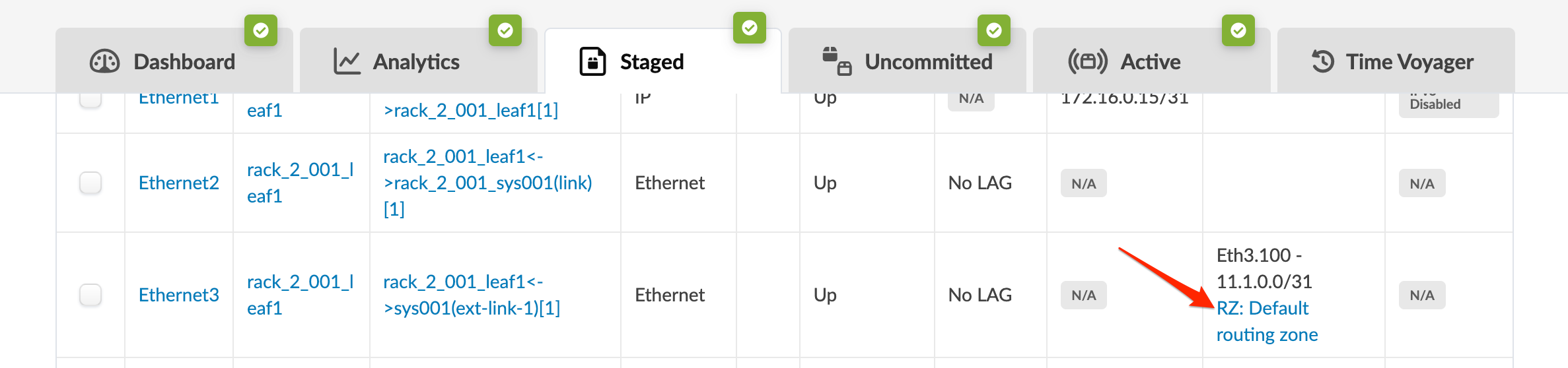
    Network management interface showing tabs for Dashboard, Analytics, Staged, Uncommitted, Active, and Time Voyager. A table lists interfaces like Ethernet2 and Ethernet3 with statuses, IP addresses, and attributes. A red arrow highlights RZ: Default routing zone linked to Eth3.100 - 11.1.0.0/31. Checkboxes are available for row selection.
  3. From the routing zone details that appear, scroll to the Interfaces section, click the checkbox for the routing zone, then click the Edit IP Addresses button that appears above the table.
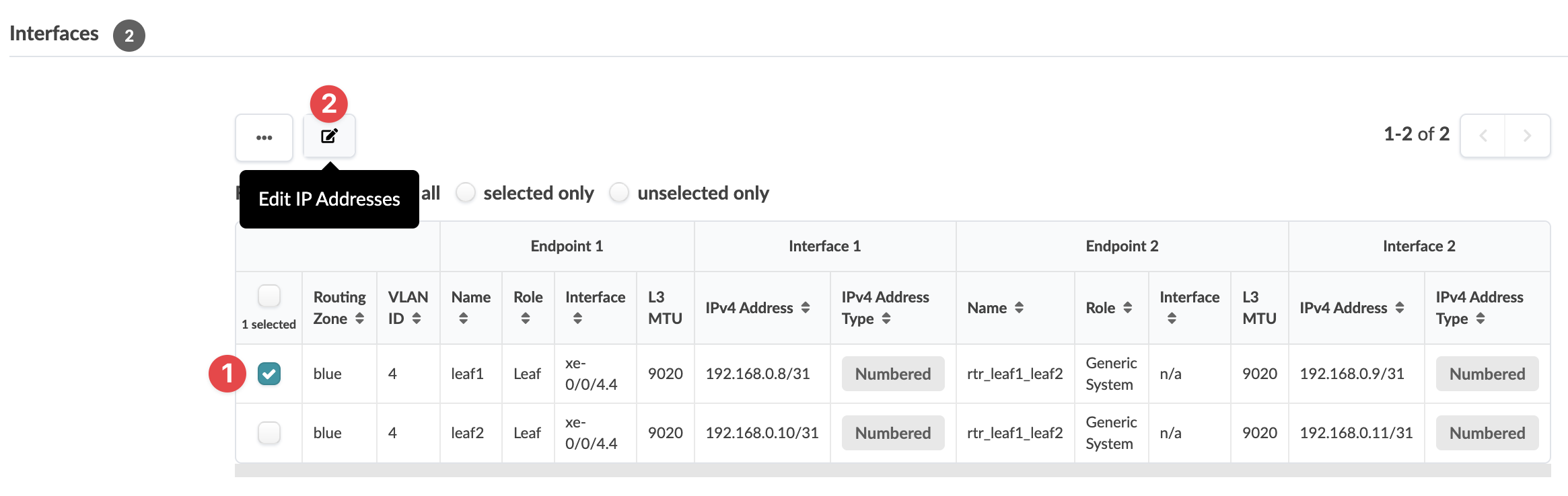
    Network management interface showing interfaces table with routing zone Default routing zone, VLAN ID 100, endpoints, and Edit IP Addresses button.
  4. In the dialog that opens, change the IP addresses (and IP address type), as applicable, then click Save to save your changes and return to the previous screen.
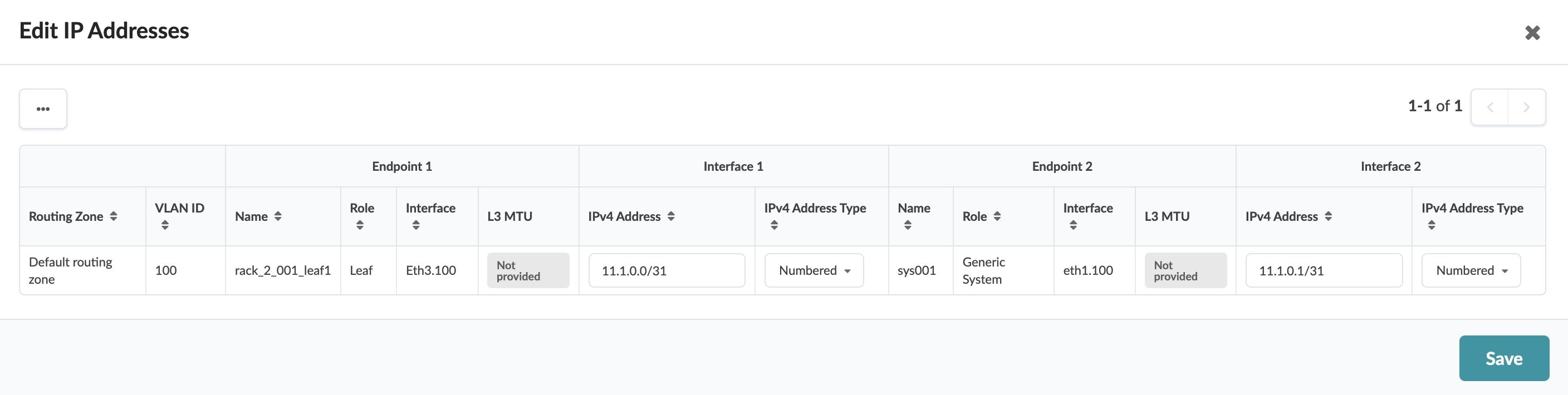
    User interface for editing IP addresses. Table with network endpoints: rack_2_001_leaf1 as Leaf and sys001 as Generic System. Save button available.

To deploy the change to the active blueprint, commit from the Uncommitted tab.

From Selection Interfaces Table

  1. From the blueprint, navigate to Staged > Physical > Topology and select the leaf with the applicable interface.
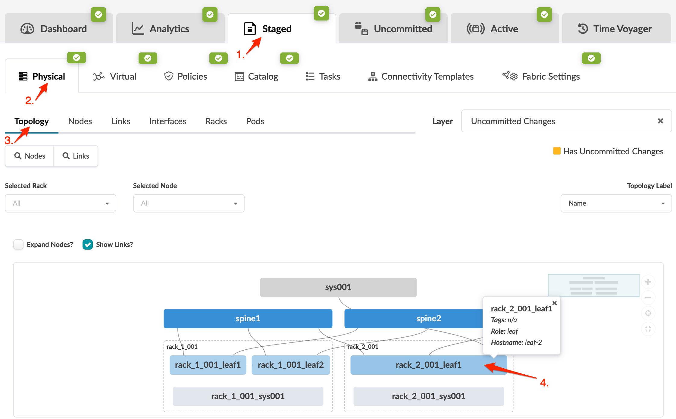
    Staged tab selected in network tool shows physical topology with nodes and links. Node rack_2_001_leaf1 highlighted with details.
  2. Above the topology for the selected node that appears, click Interfaces (next to Neighbors and Links) to go to the Interfaces table just for that node.
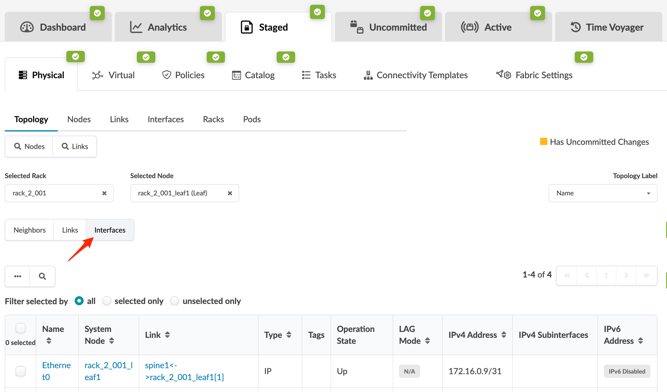
    Network management interface showing Physical topology view with Nodes, Links, Interfaces, Racks, and Pods. Active tab: Interfaces, displaying Ethernet0 details for rack_2_001_leaf1.
  3. Click the applicable routing zone in the IPv4 Subinterfaces column.
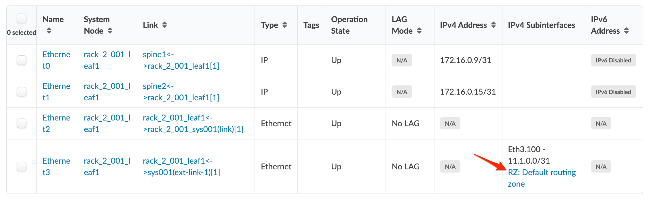
    Network interface configuration table displaying Ethernet interfaces with details such as names, states, IP addresses, and links. Highlighted: subinterface Eth3.100 with IPv4 11.1.0.0/31 in Default routing zone.
  4. From the routing zone details that appear, scroll to the Interfaces section, click the checkbox for the routing zone, then click the Edit IP Addresses button that appears above the table.
    Network management interface showing interfaces table with routing zone Default routing zone, VLAN ID 100, endpoints, and Edit IP Addresses button.
  5. In the dialog that opens, change the IP addresses (and IP address type), as applicable, then click Save to save your changes and return to the previous screen.
    User interface for editing IP addresses. Table with network endpoints: rack_2_001_leaf1 as Leaf and sys001 as Generic System. Save button available.

To deploy the change to the active blueprint, commit from the Uncommitted tab.

Directly from Routing Zone

  1. From the blueprint, navigate to Staged > Virtual > Routing Zones, then click the name of the VRF in the table.
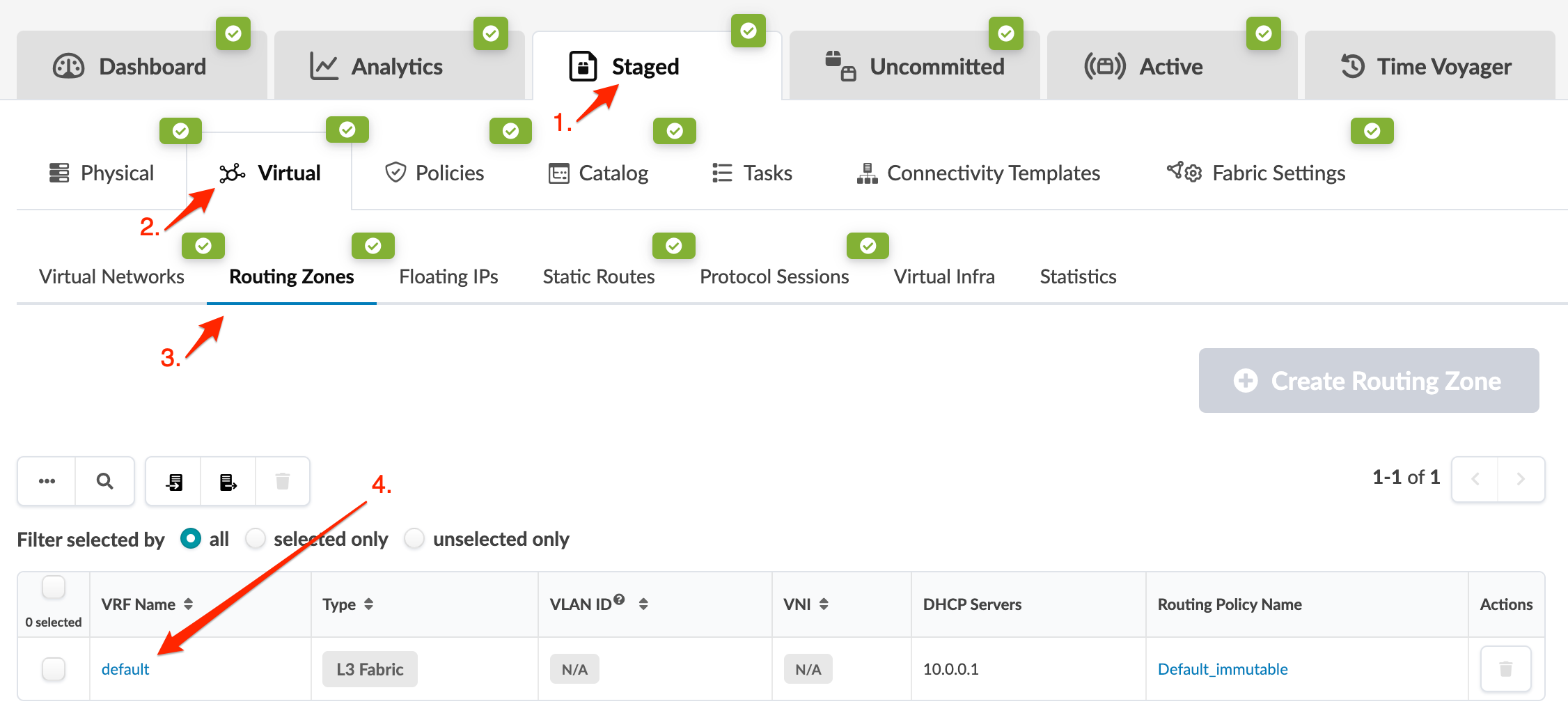
    Network management interface showing the Staged Virtual section in Routing Zones. VRF Name is default, Type is L3 Fabric, DHCP Server is 10.0.0.1, Routing Policy is Default_immutable. Options to manage or delete are available.
  2. From the routing zone details that appear, scroll to the Interfaces section, click the checkbox for the routing zone, then click the Edit IP Addresses button that appears above the table.
    Network management interface showing interfaces table with routing zone Default routing zone, VLAN ID 100, endpoints, and Edit IP Addresses button.
  3. Change the IP addresses (and IP address type), as applicable, then click Save to save your changes and return to the previous screen.
    User interface for editing IP addresses. Table with network endpoints: rack_2_001_leaf1 as Leaf and sys001 as Generic System. Save button available.

To deploy the change to the active blueprint, commit from the Uncommitted tab.