Create Internal Generic System

Systems that are not managed by the software and that are part of a rack topology are called (internal) generic systems. You specify their roles with tags. You can create an internal generic system by adding a new one or by copying an existing one.

Add Internal Generic System

To add an internal generic system using the GUI:

  1. From the blueprint, navigate to Staged > Physical > Topology and select the leaf or access switch that you want to connect to the new internal generic system.
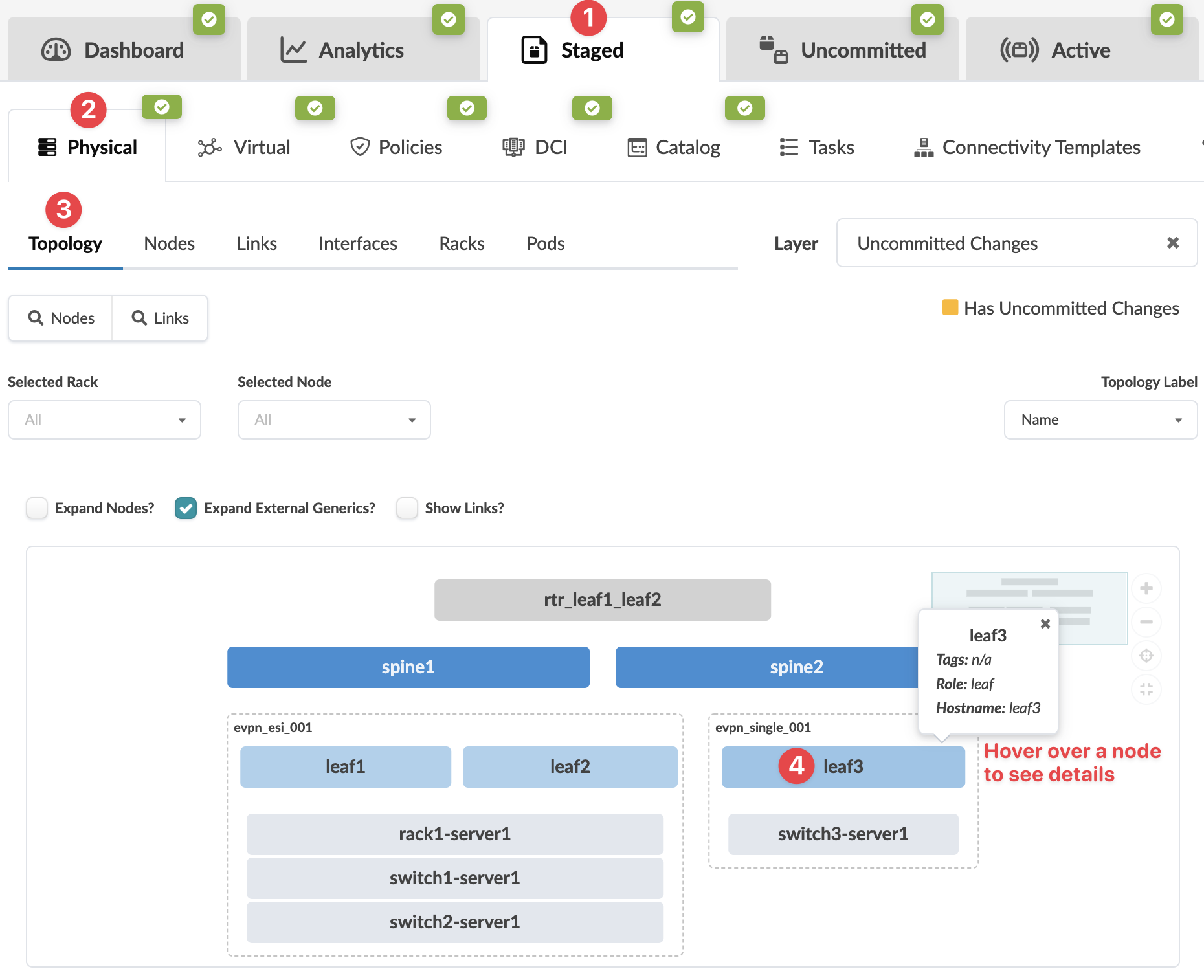
    Network management interface showing physical topology with spine nodes, leaf nodes, servers, and switches. Selected tab is Physical, sub-tab Topology. Hovering over leaf3 displays details. Filters and options for nodes and links are available. Layer shows Uncommitted Changes.
    The Topologyselection view appears.
  2. Select the node check box to see the operations available for that node (and that you have permissions for), then click Add internal/external generic system.
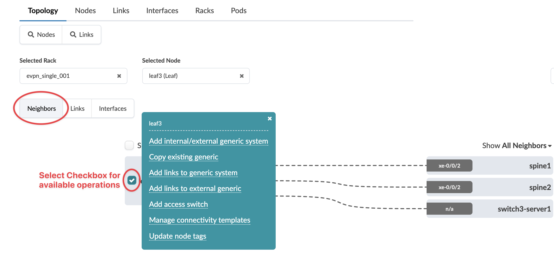
    GUI for network topology management with tabs: Topology, Nodes, Links, Interfaces, Racks, Pods. Selected Rack: evpn_single_001, Node: leaf3. Connections from leaf3 to neighbors: spine1, spine2, switch3-server1. Operations menu available with options like Add internal/external system, Copy existing, Manage templates. Dashed lines show links, interfaces labeled xe-0/0/2. Dropdown: Show All Neighbors.
    Note:

    You can also get to the selection page from the Nodes view. From the blueprint, navigate to Staged > Physical > Nodes, click the node name in the table, then click the node name that appears at the top of the Selection panel (on the right side of the page).

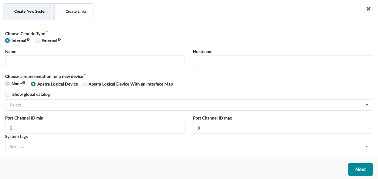
    The Create New System dialog opens.
  3. For Generic Type, select Internal.
    User interface for creating a new system with options for type, name, hostname, device representation, Port Channel ID range, system tags, and a Next button.
  4. Enter a unique name. The optional Hostname automatically populates with the same name.
  5. Select the representation for the new node (none, logical device, or logical device with interface map), then select the appropriate logical device or interface map from the drop-down list, as applicable. (Logical devices allow you to define port roles.)
  6. Enter the port channel ID min and max. If you leave the values at zero, any available port-channel may be used. Non-default port channel ranges need only be unique per system, not per blueprint.
  7. Enter tags (optional) to identify the role(s) of the new internal generic system.
  8. Click Next.
    The Create Links dialog opens
  9. Select an available port and transformation. The gray Add Link button turns green. Click Add Link.
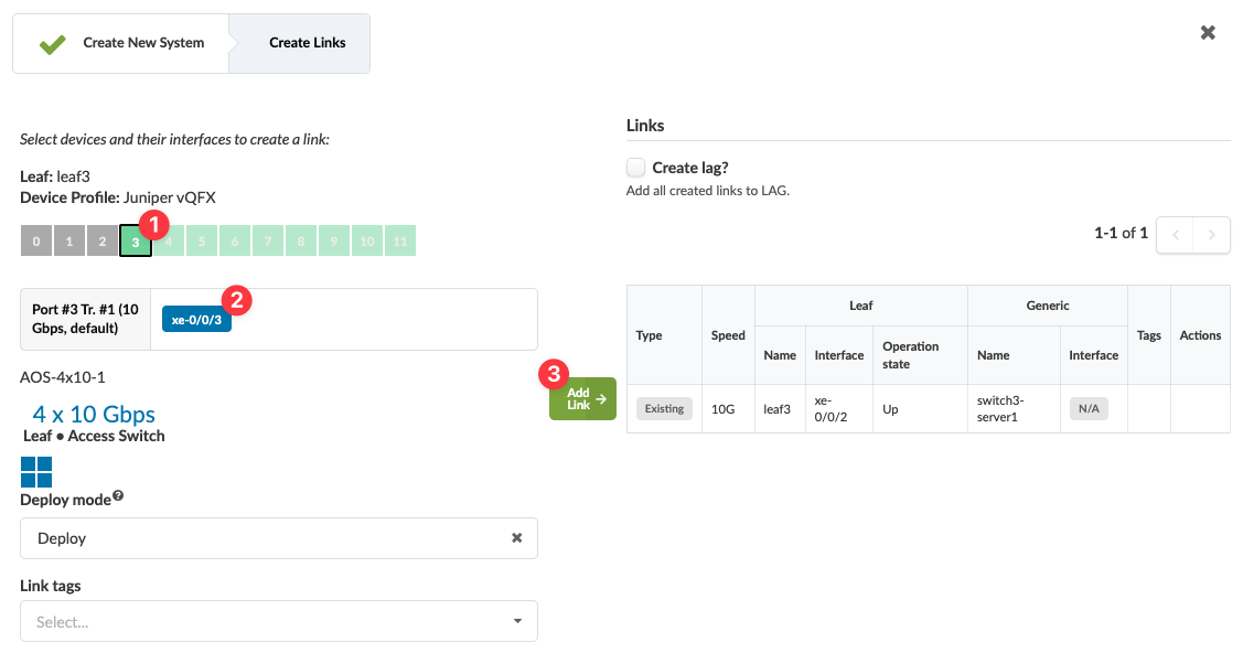
    Screenshot of a network configuration interface showing Leaf device leaf3 with Juniper vQFX profile. Port 3 xe-0/0/3 is selected with 10 Gbps speed. An existing link between leaf3 xe-0/0/2 and switch3-server1 is active at 10G. Options for link aggregation and link tags are available.
    The link is added to the link table.
  10. The operation mode for new links defaults to Up. You have the option of setting it to Down, from the drop-down list.
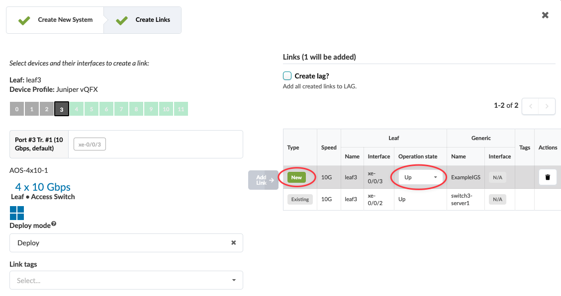
    Network configuration interface showing device leaf3 with Juniper vQFX profile. Port 3 xe-0/0/3 at 10 Gbps is selected. Adding a new link with 10 Gbps speed. Two links listed: new link xe-0/0/3 Up, existing link xe-0/0/2 Up. Option to create Link Aggregation Group unchecked. Deployment mode set to Deploy.
  11. You have the option of creating a LAG when you create a generic system. Click the Create lag check box, then select the LAG mode from the drop-down list.
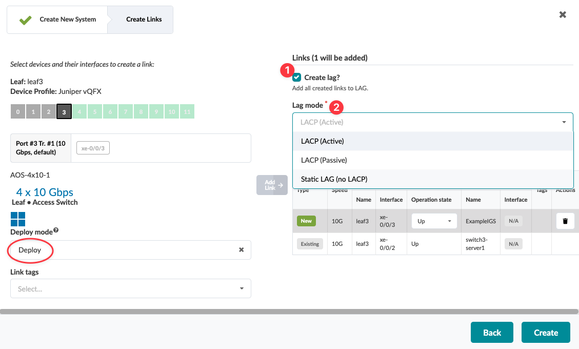
    Network configuration interface showing link creation and Link Aggregation Group settings. Device leaf3 with Juniper vQFX profile, port xe-0/0/3 for a 10 Gbps link. LAG options include LACP Active, Passive, and Static.
  12. The Deploy mode defaults to Deploy. You have the option of setting it to Undeploy, from the drop-down list. If all interfaces that are facing the generic system are admin down, then you can't set the deploy mode to Deployed.
  13. Click Create.
The change is staged and you're returned to the Topology view.

When you're ready to activate your changes, go to the Uncommitted tab to review and commit (or discard) your changes.

Copy Existing Generic System

To copy an internal generic system to create another one using the GUI:

  1. From the blueprint, navigate to Staged > Physical > Topology and select the leaf or access switch that you want to connect to the new generic system.
    Network management interface showing physical topology with spine nodes, leaf nodes, servers, and switches. Selected tab is Physical, sub-tab Topology. Hovering over leaf3 displays details. Filters and options for nodes and links are available. Layer shows Uncommitted Changes.
    The Topology view of the selection appears.
  2. Select the node check box to see the operations available for that node (and that you have permissions for), then click Copy existing generic.
    GUI for network topology management with tabs: Topology, Nodes, Links, Interfaces, Racks, Pods. Selected Rack: evpn_single_001, Node: leaf3. Connections from leaf3 to neighbors: spine1, spine2, switch3-server1. Operations menu available with options like Add internal/external system, Copy existing, Manage templates. Dashed lines show links, interfaces labeled xe-0/0/2. Dropdown: Show All Neighbors.
    Note:

    You can also get to the selection page from the Nodes view. From the blueprint, navigate to Staged > Physical > Nodes, click the node name in the table, then click the node name that appears at the top of the Selection panel (on the right side of the page).

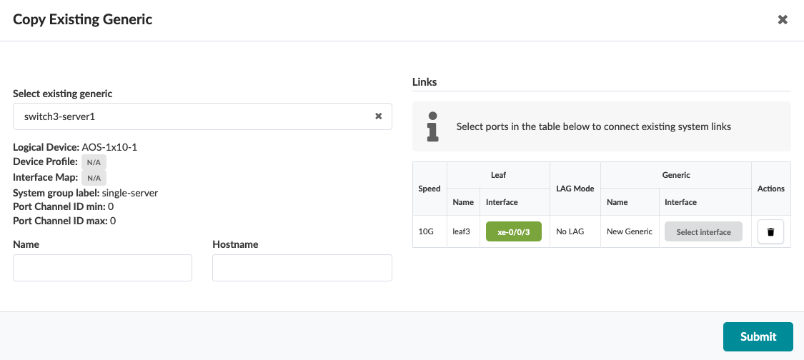
    The Copy Existing Generic dialog opens.
  3. From the drop-down list, select the existing internal generic system to copy, then in the Links table that appears, click Select interface.
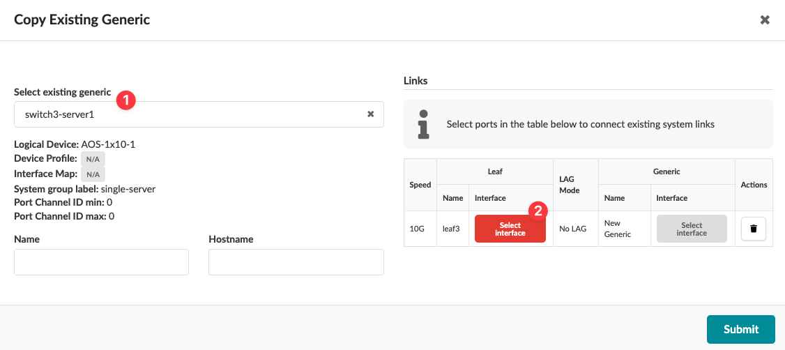
    User interface for copying a generic network configuration, including dropdown to select an existing configuration, device details, link port table, and submit button for confirmation.
    The Select interface dialog opens.
  4. Select a port and transformation, then click Confirm.
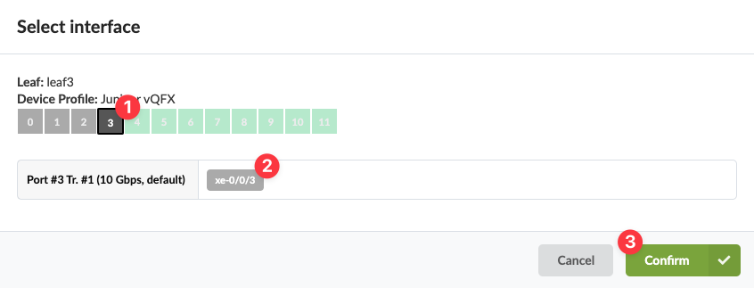
    Select network interface on device leaf3 with profile Juniper vQFX. Interface 3 highlighted. Confirm or cancel selection.
    The Copy Existing Generic dialog opens again.
  5. Click Submit.
    User interface for copying an existing generic configuration in a network management system. Includes title Copy Existing Generic, dropdown to select existing configuration, details of selected configuration, empty input fields for Name and Hostname, table for link settings with options for speed, leaf, LAG mode, generic interface, and actions, and a Submit button.
The change is staged and you're returned to the Topology view.

When you're ready to activate your changes, go to the Uncommitted tab to review and commit (or discard) your changes.

Note:

You can also create generic systems when you create rack types during the Design phase.