DCI Overview
ESI MAC Most Significant Byte
By default, ESI MAC msb (most significant byte) is set to 2 on all blueprints. Every HPE Networking Apstra Data Center Director blueprint that's connected must have a unique msb to prevent service-impacting issues. Before creating remote EVPN gateways, change ESI MAC msb accordingly. (You can leave one of them at the default value.)
Apstra DC Director is programmed to assign a unique ESI MAC address starting with the value 00.00.00.00.00.01.
This feature allows you to manually configure the most significant byte (MSB) of the MAC address.
Updating this value results in the regeneration of all ESI MACs in the blueprint. This is necessary to address the Apstra data center interconnect (DCI) use case requirement where ESI values must be unique across multiple fabrics (blueprints). For example, if you have data centers DC1, DC2, and DC3 all managed by Apstra DC Director and connected via Apstra DCI, by default, each of them will have the same internally generated ESI MAC. You would use this feature to provide a unique value to DC2 and DC3.
DCI / EVPN Gateway Overvew
Historically, enterprises have leveraged Data Center Interconnect (DCI) technology as a building block for business continuity, disaster recovery (DR), or Continuity of Operations (COOP). These service availability use cases primarily relied on the need to connect geographically separated data centers with Layer 2 connectivity for application availability and performance.
With the rise of highly virtualized Software-Defined Data Centers (SDDC), cloud computing, and more recently, edge computing, additional use cases have emerged:
- Colocation Expansion: Share compute and storage resources to colocation data center facilities.
- Resource Pooling: Share and shift applications between data centers to increase efficiency or improved end-user experience.
- Rapid Scalability: Expand capacity from a resource-limited location to another facility or data center.
- Legacy Migration: Move applications and data off older and inefficient equipment and architecture to more efficient, higher-performing, and cost-effective architecture.
You can deploy and manage a vendor inclusive DCI solution that is simple, flexible, and Intent-Based. The standards-based MP-BGP EVPN with VXLAN is utilized, which has achieved broad software and hardware adoption in the networking industry. You can choose from a vast selection of cost-effective commodity hardware from traditional vendors to white-box ODMs and software options ranging from conventional vendor integrated Network Operating Systems (NOS) to disaggregated open source options.
EVPN VXLAN is a standards-based (RFC-7432) approach for building modern data centers. It incorporates both data plane encapsulation (VXLAN) and a routing control plane (MP-BGP EVPN Address Family) for extending Layer 2 broadcast domains between hosts as well as Layer 3 routed domains in spine-leaf networks. Relying on a pure Layer 3 underlay for routing of VXLAN tunneled traffic between VXLAN Tunnel Endpoints (VTEPs), EVPN introduces a new address family to the MP-BGP protocol family and supports the exchange of MAC/IP addresses between VTEPs. The advertisement of endpoint MACs and IPs, as well as "ARP/ND-suppression", eliminates the need for a great majority of Broadcast/Unknown/Multicast (BUM) traffic and relies upon ECMP unicast routing of VXLAN, from Source VTEP to Destination VTEP. This ensures optimal route selection and efficient load-sharing of forwarding paths for overlay network traffic.
Just as EVPN VXLAN works within a single site for extending Layer 2 between hosts, the DCI feature enables Layer 2 connectivity between sites. The DCI feature enables the extension of Layer 2 or Layer 3 services between data centers for disaster recovery, load balancing of active-active sites, or even for facilitating the migration of services from one data center to another.
Limitations: EVPN-GW (DCI) between different vendors' EVPN fabric is not supported.
DCI Deployment Options
The following characteristics apply to all deployment options:
- You can extend DCI to other Apstra DC Director-managed data centers, non-Apstra DC Director-managed data centers, or even to legacy non-spine-leaf devices.
- Implementation and behavior is the same in all three cases.
- Whether the remote end is another DCI GW or an ASBR, it is transparent.
- Neither the GWs nor ASBRs are managed.
You can implement Data Center Interconnect using the following methods. For assistance with selecting the best option for your organization, consult your Solutions Architect (SA) or Systems Engineer (SE).
Over the Top
DCI "Over the Top" is a transparent solution, meaning EVPN routes are
encapsulated into standard IP and hidden from the underlying transport. This
makes the extension of services simple and flexible and is often chosen because
data center teams can implement it with little to no coordination with WAN or
Service Provider groups. This reduces the implementation times and internal
company friction. However, the tradeoff is scalability and resilience. 
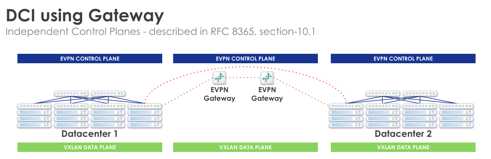
Gateway (GW)
Building upon the Remote EVPN Gateway capability, you can optionally
specify that the Remote EVPN Gateway is an external generic system
(tagged as an external router) in the same site, thus extending the EVPN
attributes to said gateway. This solution creates a fault domain per site,
preventing failures from affecting convergence in remote sites and creating
multiple fault domains. IP/MAC endpoint tables for remote sites are processed
and held in state on a generic system (tagged as external router) gateway. You
can also implement WAN QoS and security, along with optimizations that the
transport technology makes available (MPLS TE for example). However, this
solution is more operationally complex, requiring additional hardware and cost.
Autonomous System Border Router (ASBR)
Using the Remote EVPN Gateway capability, you can optionally specify that
the Remote EVPN Gateway is an ASBR WAN Edge Device. This end-to-end EVPN
enables uniform encapsulation and removes the dedicated GW requirement. It is
operationally complex but has greater scalability as compared to both "DCI Using
Gateway" and "Over the Top". 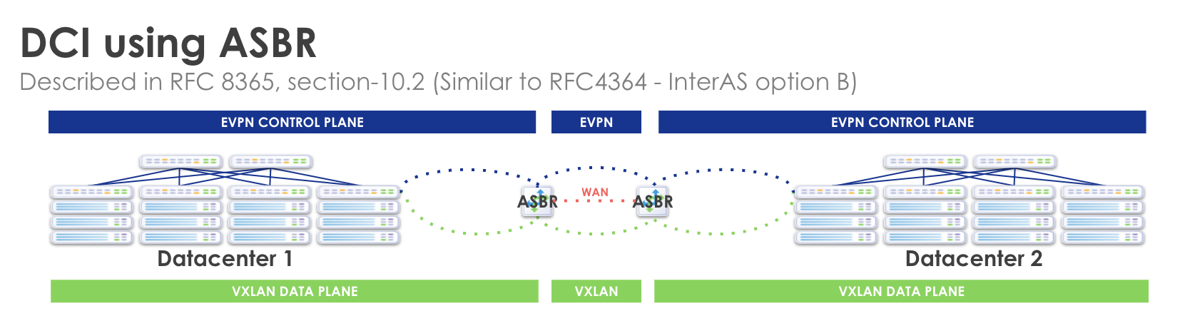
Data Plane Extension
Data Plane Extension: Layer 3
VXLAN Network IDs (VNIDs) are a part of the VXLAN header that identify unique VXLAN tunnels, each of which are isolated from the other VXLAN tunnels in an IP network. Layer 3 packets can be encapsulated into a VXLAN packet or Layer 2 MAC frames can be encapsulated directly into a VXLAN packet. In both cases, a unique VNID is associated with either the Layer 3 subnet, or the Layer 2 domain. When extending either Layer 3 or Layer 2 services between sites, you are essentially stitching VXLAN tunnels between sites. VNIDs therefore need to match between sites.
It is important to understand that a particular VNID will be associated with only
one VRF (or routing zone in Apstra DC Director terminology). VNIDs exist within
a VRF. They are tied to a VRF. For Layer 3 services, the stitching, or
extending, of each VNID is done with the export and import of RTs within a
routing zone (VRF). Layer 3 subnets (routes) are identified via RTs. All VNIDs
are exported automatically at the EVPN gateway (edge) towards the WAN.
Conversely, RTs of the same value are automatically imported at the EVPN gateway
(edge) coming into the fabric. So if you coordinate the Layer 3 VNIDs at one
site to match the other, no additional configuration is needed. 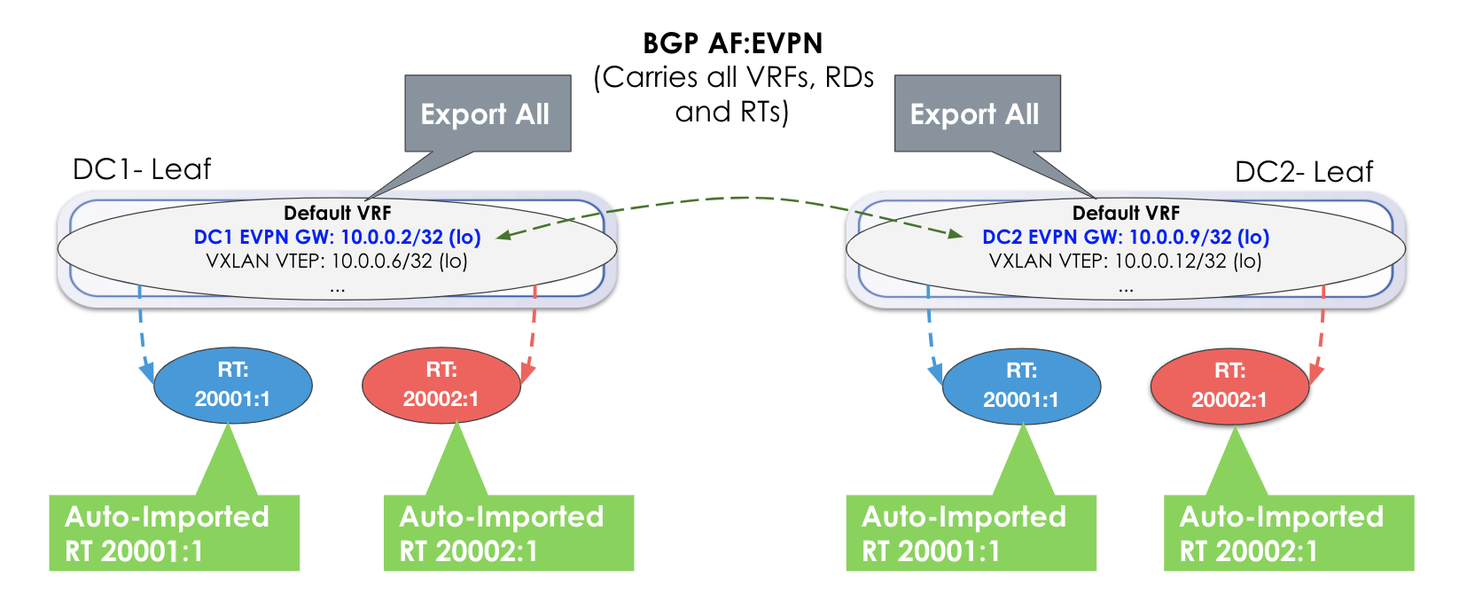
In the image above, no additional export or import is required. Everything is automatically exported (Export All) and because the RTs match, they are automatically imported.
However, if a VNID in DC1 is different from a VNID in DC2, then you must import
the RTs respectively. Each respective gateway still automatically imports RTs of
the same value. In the example below, an additional step of manually adding the
RTs from the other site is required. 
Data Plane Extension: Layer 2
A virtual network can be a pure Layer 2 service (Layer 3 anycast gateway is not instantiated). It can be rack-local (VLAN on server-facing ports contained within a rack) or VXLAN (select the racks to extend the Layer 2 flood and broadcast domain between racks. This Layer 2 domain has its own VNID, and the MAC frames (as opposed to IP packets) are encapsulated into the VXLAN header with the VNID of the Layer 2 domain.
The same principles apply in that all VNIDs are exported at the EVPN gateway (in this case Type-2 routes/MAC addresses), and matching RTs are automatically imported. However, the location of importing and exporting RTs is not at the routing zone level, but instead at the virtual network itself.