Integrated DCI (VXLAN Stitching)

Overview

Note:

Apstra DC Director also supports two other types of DCI:

  • External Handoff where an external connection is set with a standard Layer 2 VLAN handoff external connection with traditional Flood MA VLAN learning. This extends a single Network/Broadcast domain with a traditional demarcation point.

  • OTT (over the top) Extending the Single EVPN-VXLAN domain between data centers.

Initial Apstra Integrated DCI is being qualified with the following models using Junos OS 23.2R: QFX5700, QFX5130, QFX1000.

Integrated DCI, also known as VXLAN stitching, allows users to extend EVPN Type 2 and Type 5 routes between data centers using designated border leaf(s) to act as DCI gateways at each data center.

Note:

When creating a route policy for Type 5 routes in a VRF, explicitly add the BGP routes to the Extra Export Routes list. This ensures that the routes are advertised to the DCI gateways and are available to the corresponding VRFs in other blueprints.

  • Apstra's Integrated DCI reference design follows RFE-9014 and draft-sharma-bess.

  • Each data center is treated as its own independent domain.

Configuring Integrated DCI within Apstra DC Director:

  • DCI configuration must be configured as part of each data center deployment/blueprint and use the same Interconnect Route Target (iRT).

  • The steps below guide you through the process for each blueprint and deployment.

1. Configure ESI MAC MSB

All data centers must be configured to use a different ESI MAC MSB (most significant byte). Refer to Update ESI MAC MSB for details.

2. Create Interconnect Domain

  1. From the blueprint, navigate to Staged > DCI > Integrated Interconnect and click Create Interconnect Domain.
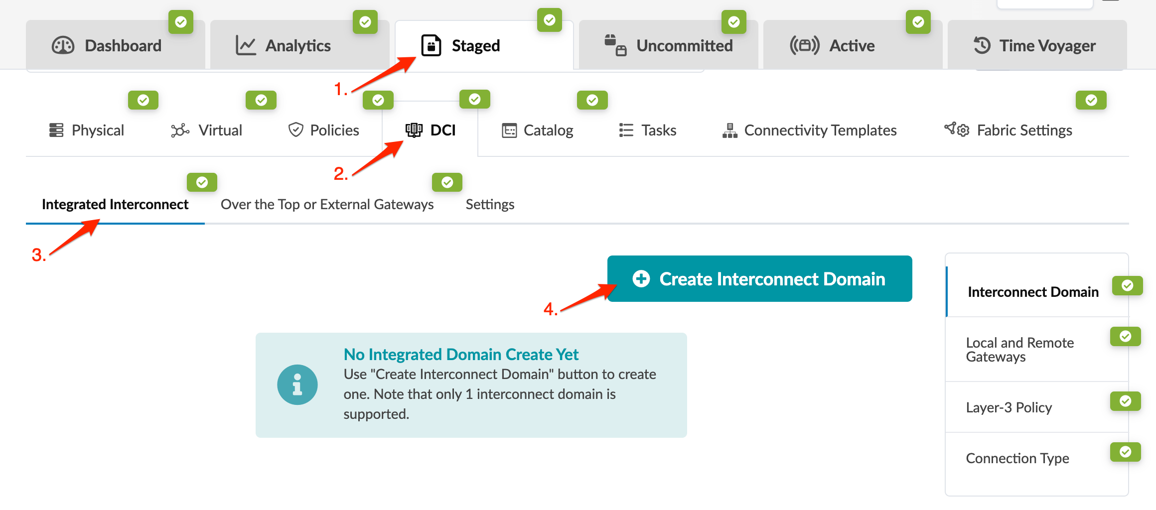
    Network management interface showing tabs for navigation, options like policies and connectivity templates, and a selected Integrated Interconnect tab with a button to create an interconnect domain.
    The Create Interconnect Domain dialog opens.
  2. Enter the following information:
    • Interconnect Domain Name

    • Interconnect Route Target (iRT) - All interconnect gateways must use the same iRT. The iRT is an additional unique RT for the interconnect domain. The iRT must be globally unique; it must not be in use for every DCI-connected data center.

    • Interconnect ESI (optional) - Each site requires a unique site ID iESI at the MAC-VRF level, either auto-derived or set manually.

  3. Click Update to create the interconnect domain and return to the Integrated Interconnect page.

3. Create Remote Interconnect Gateway

  1. From the Integrated Interconnect page, click Local and Remote Gateways.
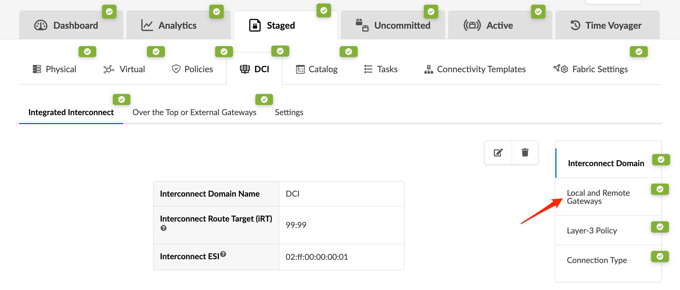
    Network management interface showing tabs like Dashboard, Analytics, Staged, and Active, with Local and Remote Gateways highlighted under Integrated Interconnect settings.
  2. Click Create Remote Interconnect Gateway.
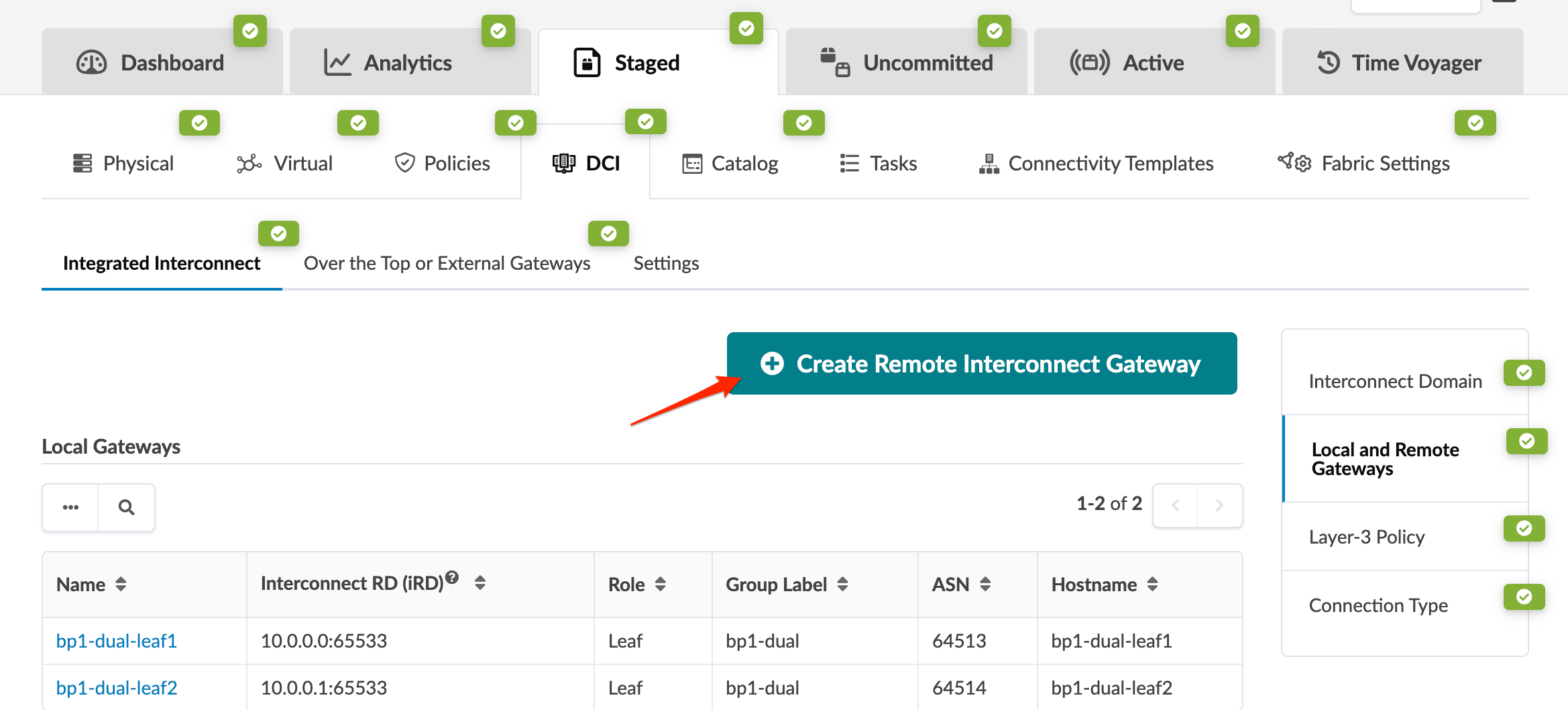
    User interface of a network management tool showing the Integrated Interconnect section with tabs like Dashboard, Analytics, and Time Voyager. Focused on Local and Remote Gateways table with details such as names, roles, and hostnames. Button labeled Create Remote Interconnect Gateway is highlighted for action.
    The Create Remote Interconnect Gateway dialog opens.
  3. Enter a name for the remote border leaf interconnect gateway and add the remote BGP IP/ASN. Select the local border leaf devices that will establish a session with this remote DCI gateway.
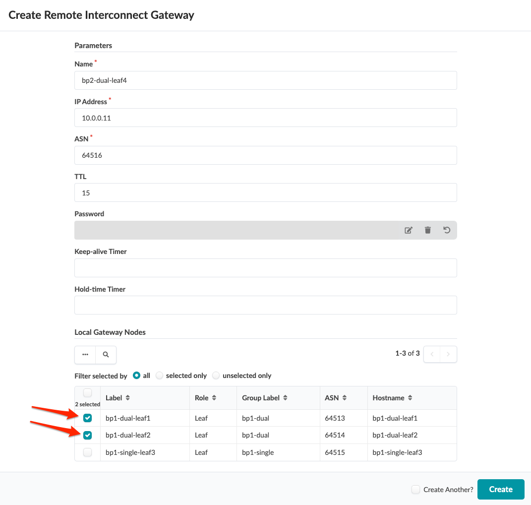
    User interface for creating a Remote Interconnect Gateway with input fields for Name, IP Address, ASN, TTL, Password, Keep-alive Timer, and Hold-time Timer. Two selected nodes, bp1-dual-leaf1 and bp1-dual-leaf2, are listed in a table. Filter options include all, selected only, or unselected only. Create button is at the bottom right with a Create Another checkbox.
  4. Click Create to create the gateway and return to the Integrated Interconnect page.

4. Create Routing Policy

  1. From the Integrated Interconnect page, click Layer-3 Policy.
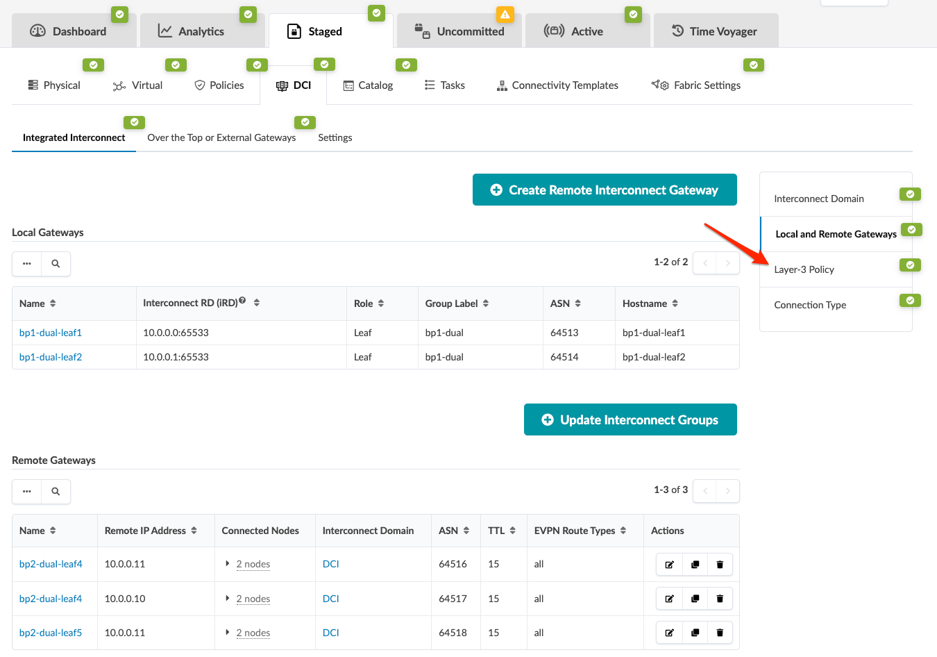
    Network management interface for configuring interconnect gateways, showing sections for local and remote gateways with details like names, roles, hostnames, IPs, and EVPN route types. Options to create or update gateways and groups are included. Tabs for settings and configurations are visible.
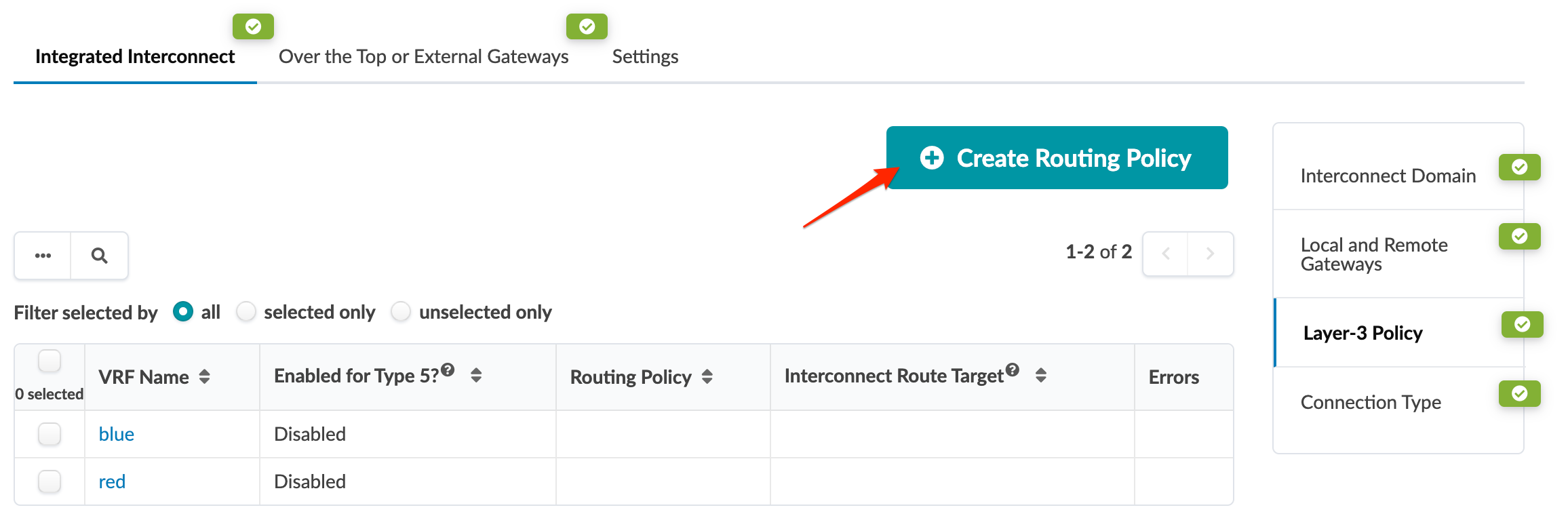
  2. Click Create Routing Policy.
    User interface for managing network configurations, showing tabs for routing policies, a table with VRF details, filter options, and a button to create routing policies.
    The Create Routing Policy dialog opens.
  3. You can create a routing policy that can be used with VRF routes to exchange and extend the EVPN Type 5 routes via Integrated DCI. If you only plan to extend VNI and exchange EVPN Type 2 routes then you don't need to enable the VRFs for DCI EVPN Type 5 route exchange. The example below is for a route-map policy for the blue VRF.
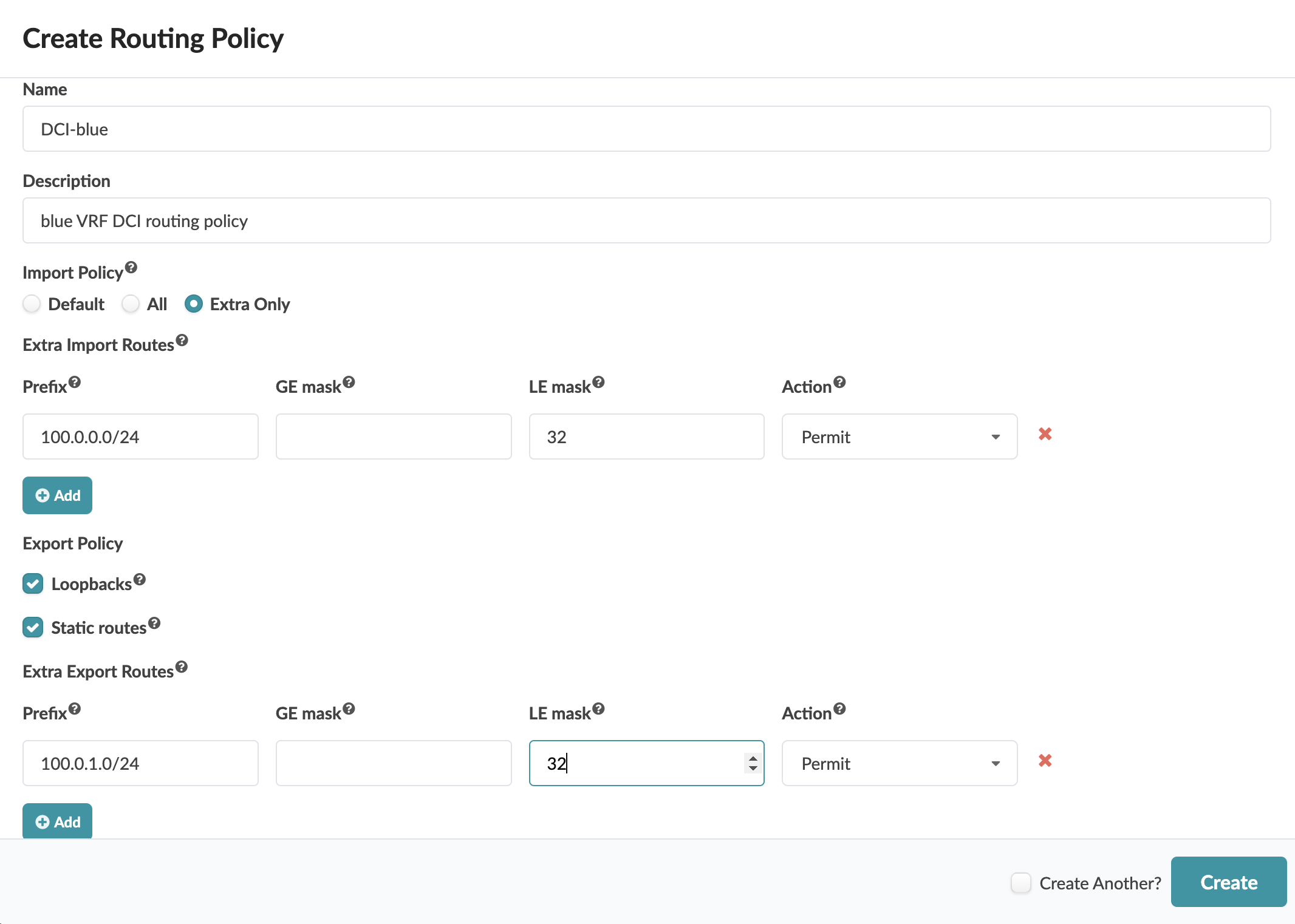
    User interface for creating a routing policy with fields for name, description, import and export settings, extra routes, and options to add routes or create another policy.
  4. After entering routing policy details, click Create to create the routing policy and return to the Integrated Interconnect page.
  5. To assign the routing policy and enable the VRF for DCI Type 5 route exchange (as applicable), select the check box for the VRF, then click the Edit button that appears above the table.
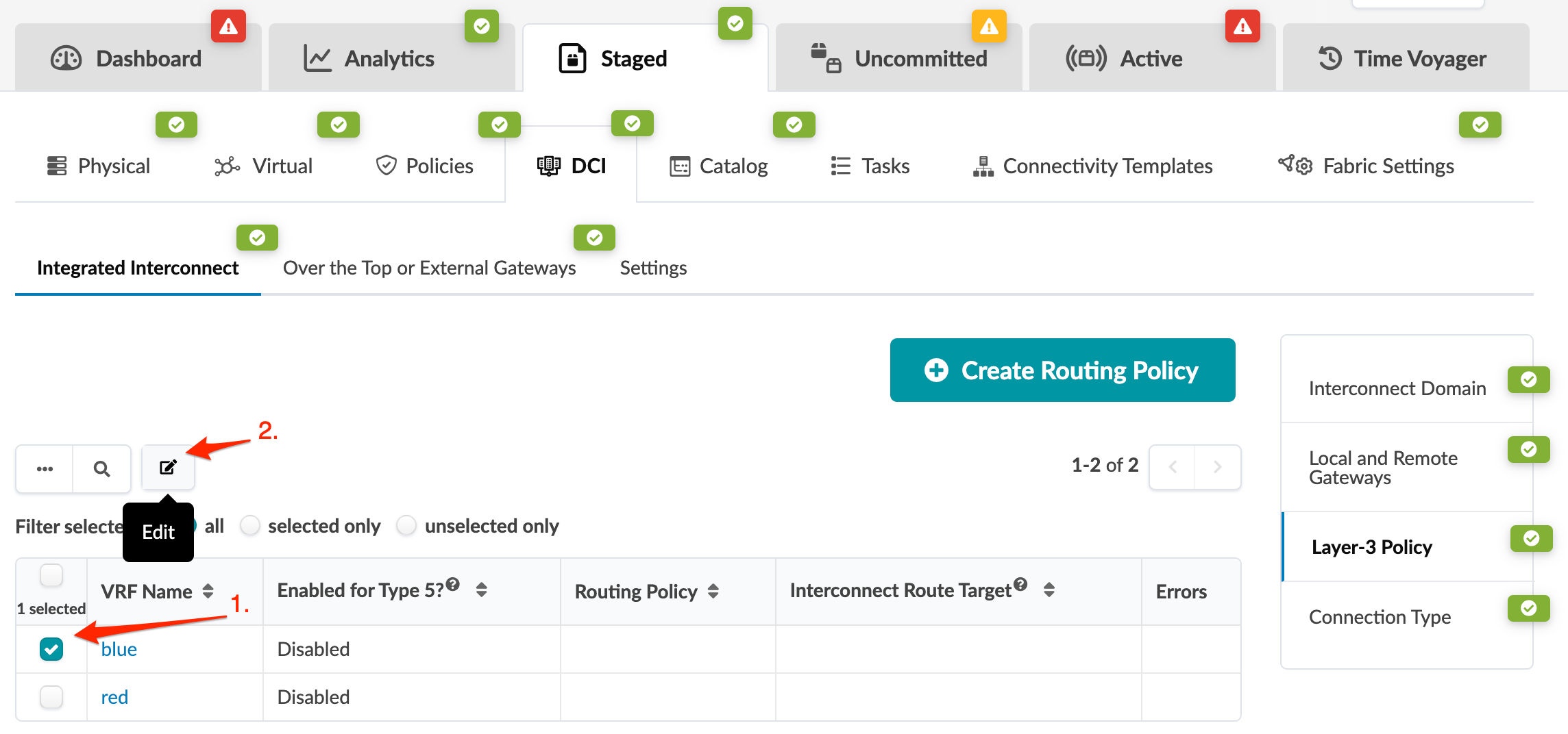
    Network management interface showing tabs like Dashboard, Analytics, and Time Voyager, a Routing Policy table with columns VRF Name, Routing Policy, and Errors, selected checkbox for VRF blue, Edit button highlighted, and Create Routing Policy button visible.
    The Update Layer-3 Policy dialog opens
  6. Toggle on Type 5 enablement (if applicable), select the routing policy from the drop-down list, and enter the iRT. Interconnect gateways must use the same Interconnect Route Target (iRT). The iRT is an additional unique route target for the interconnect domain.
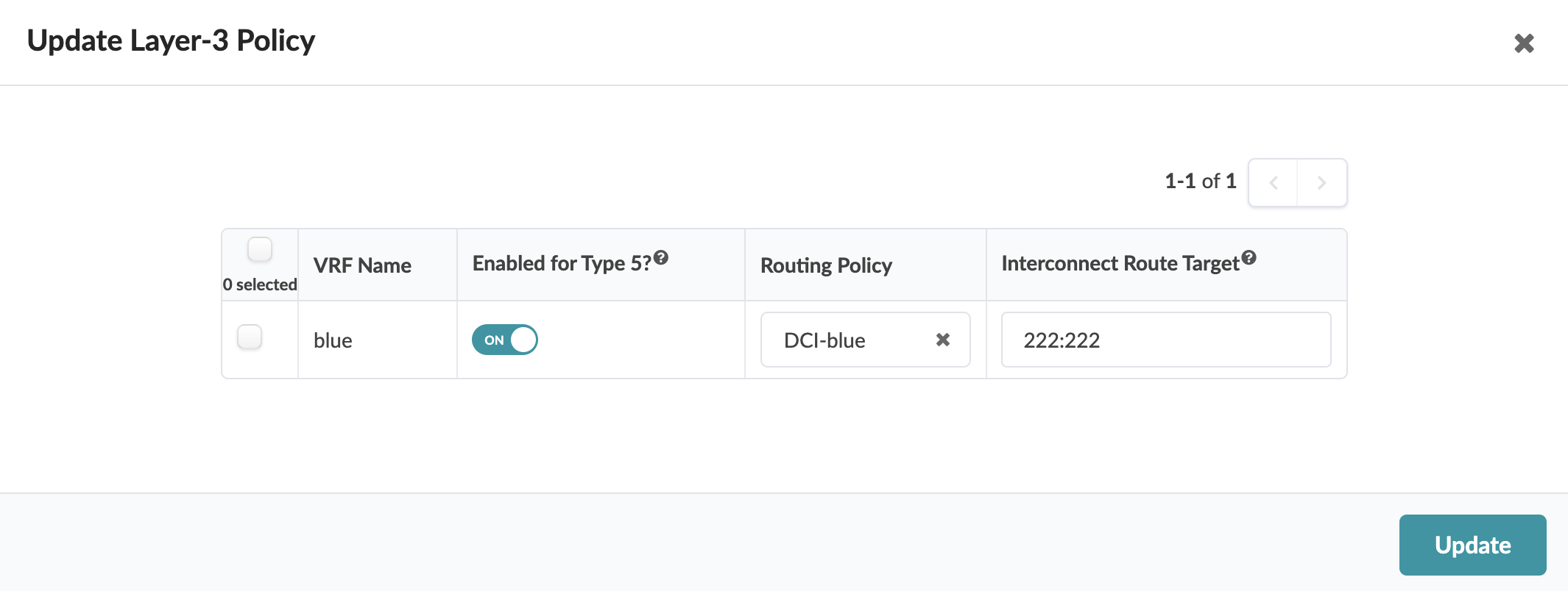
    User interface for updating Layer-3 policy with table showing VRF Name blue, Enabled for Type 5 toggled on, Routing Policy DCI-blue, Interconnect Route Target 222:222, and Update button at bottom right.
  7. Click Update to save your changes and return to the Integrated Interconnect page.

5. Update Connectivity Type

This configuration section allows extending VNI EVPN Type 2 routes across data centers via Integrated DCI. Let's configure virtual networks to be exchanged via Integrated DCI.
  1. From the Integrated Interconnect page, click Connection Type (in right panel).
  2. Select the check boxes for the Layer 2 virtual networks and Layer 3 VRFs that need to extend to the remote DCI gateway. Remember, for every VRF that is to be enabled for Type 5 EVPN route exchange, it must be enabled on the Layer-3 Policy tab.
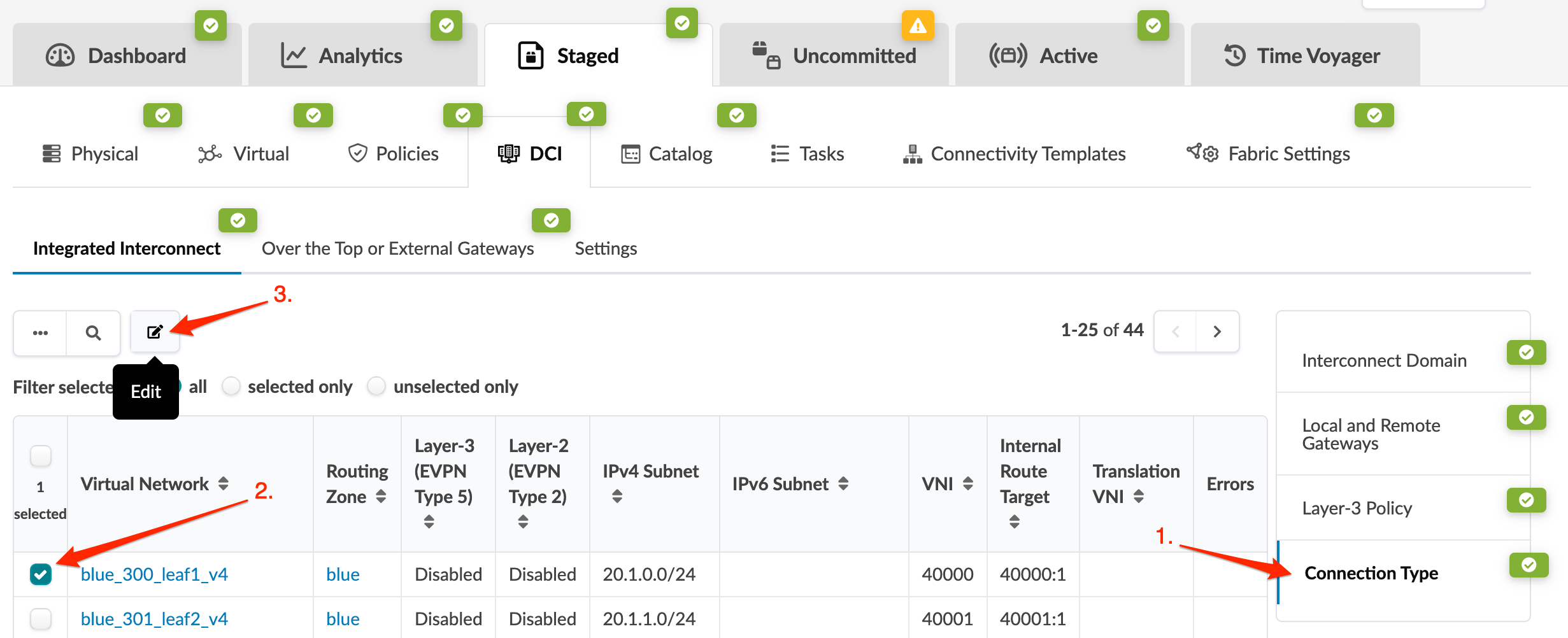
    User interface of a network management tool showing tabs like Dashboard, Analytics, and Time Voyager, submenu options like Physical and Virtual, the Integrated Interconnect section with sub-tabs Over the Top Gateways and Settings, a table of virtual networks with columns for Routing Zone and Subnets, and highlighted actions including connection type, selected virtual network blue_300_leaf1_v4, and edit button.
  3. Click the Edit button that appears above the table.
    The Update Connectivity Type dialog opens.
  4. Enable Layer 2 EVPN Type 2 route exchange. Translation VNI is the intermediate VNI to be used. It isn't required, but it needs to match the remote VNI either by translation on the other side or by both data centers using the same VNI for the virtual network that's being extended.
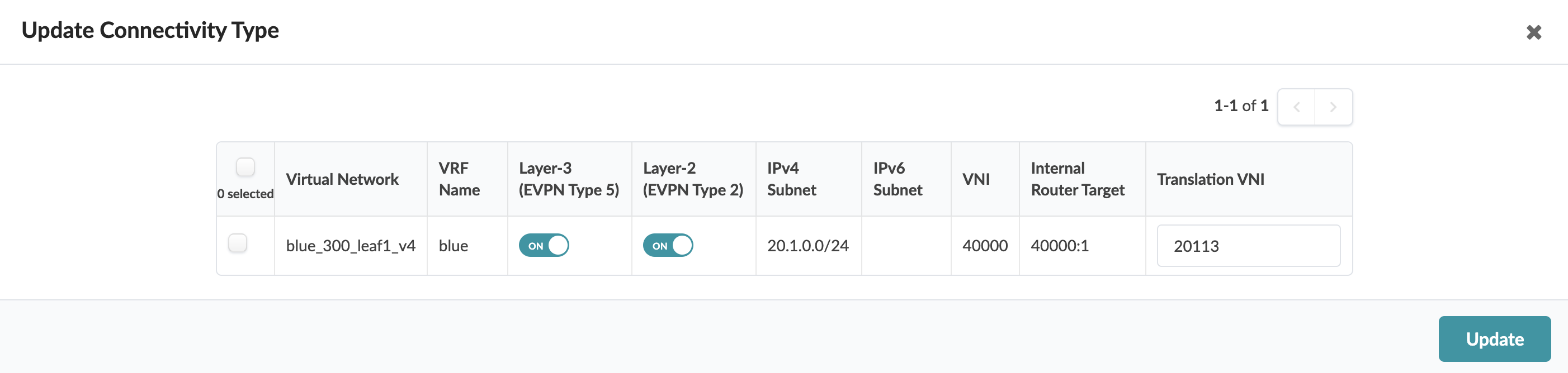
    Update Connectivity Type interface showing a table with columns for network details. A row displays Virtual Network blue_300_leaf1_v4, VRF Name blue, Layer-3 EVPN Type 5 ON, Layer-2 EVPN Type 2 ON, IPv4 Subnet 20.1.0.0/24, IPv6 Subnet empty, VNI 40000, Internal Router Target 40000:1, Translation VNI 20113. Row selection checkbox and Update button included.
  5. Click Update to save your changes and return to the Integrated Interconnect page.
  6. After enabling all virtual networks and VRFs that will be extended to the remote DCI gateway, ensure that the Uncommitted tab is green and that you can commit the changes to enable the local Integrated DCI gateways that have been configured. (You'll repeat all these steps for the remote DCI gateway.)
Repeat the process for all Layer 2 virtual networks and Layer 3 VRFs that need to extend to the remote DCI gateway. Remember, every VRF that is to be enabled for Type 5 EVPN route exchange must be enabled on the Layer-3 Policy tab.

6. Configure Remote DCI Gateway

Repeat the above steps to configure the remote DCI gateway.