Add Links to Spine

To add links to a spine using the GUI:
  1. From the blueprint, navigate to Staged > Physical > Topology and select a node that can connect to a spine. In our example, we've selected an external generic system.
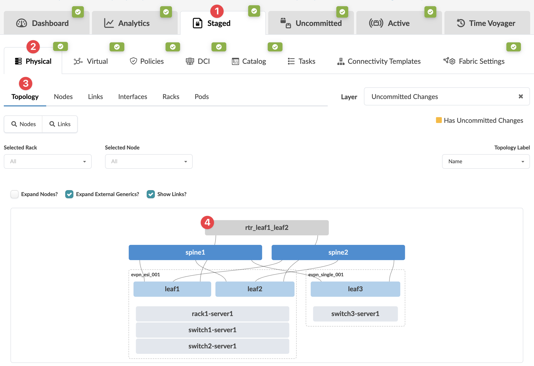
    Network management interface showing tabs for Dashboard, Analytics, Staged, and others. Topology view with spine-leaf architecture: two spine nodes, three leaf nodes, and connected devices. Uncommitted changes layer is active.
    The Topology selection view appears.
  2. Select the node check box to see the operations available for that node (and that you have permissions for).
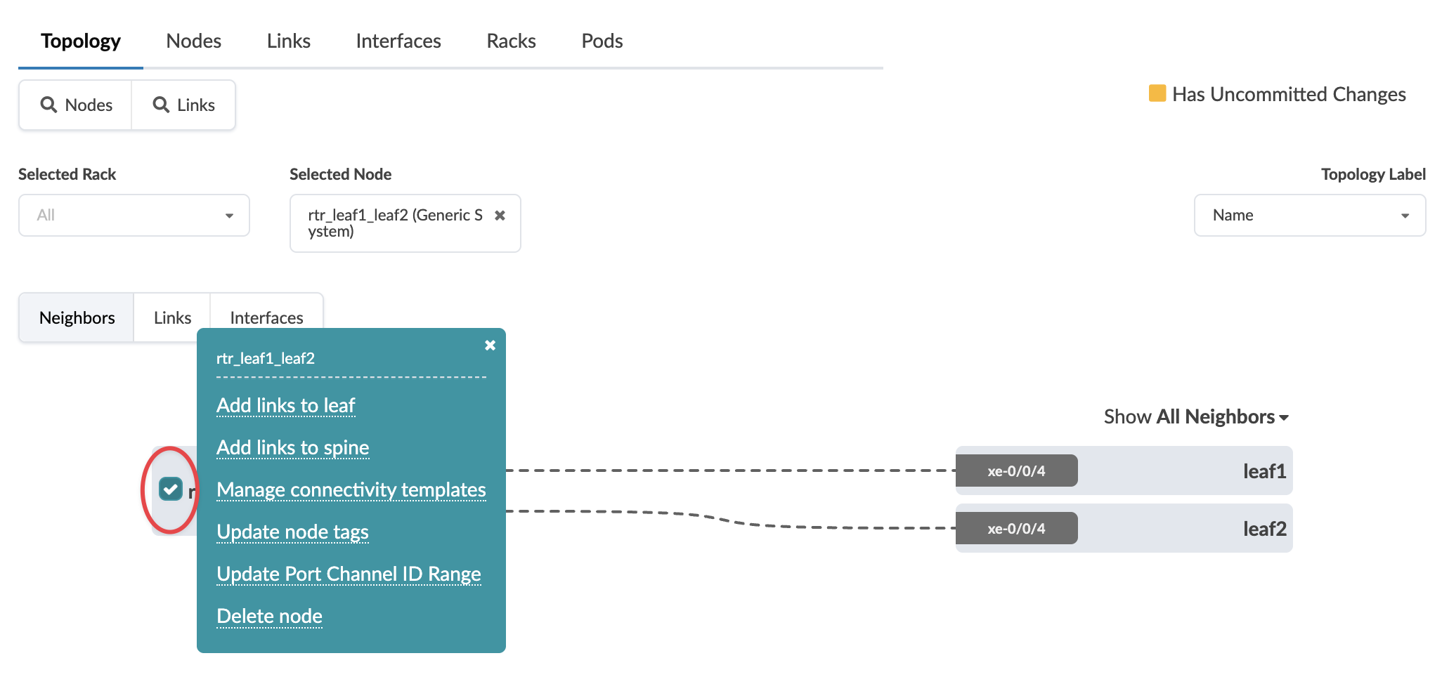
    Network management interface showing Topology tab with node rtr_leaf1_leaf2 selected. Node options menu open with choices like Add links to leaf. Neighbors tab displays connections to leaf1 and leaf2 via xe-0/0/4. Uncommitted changes indicator visible.
    Note:

    You can also get to the selection page from the Nodes view. From the blueprint, navigate to Staged > Physical > Nodes, click the node name in the table, then click the node name that appears at the top of the Selection panel (on the right side of the page).

  3. Click Add links to spine.
    The Create Links dialog opens.
  4. Select the spine to link to from the drop-down menu.
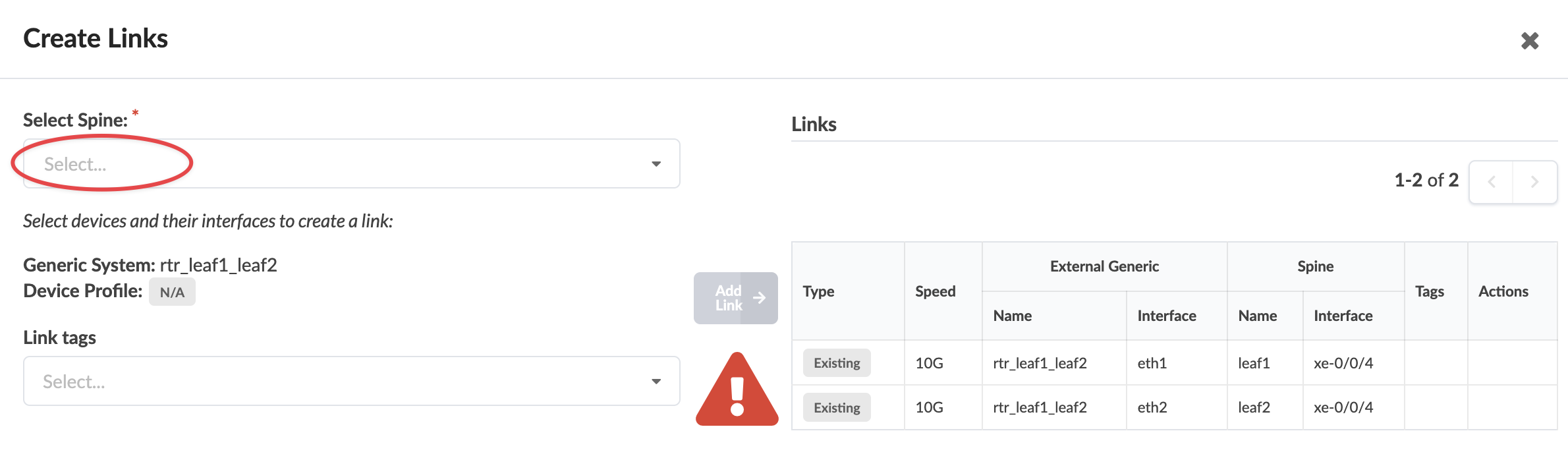
    User interface for creating network links with a dropdown for selecting spine, empty link tags field, existing links table showing two 10G connections, and a disabled Add Link button highlighted by a red warning icon. Pagination shows 1-2 of 2 entries.
    Ports and transformations appear.
  5. Select an available port and transformation.
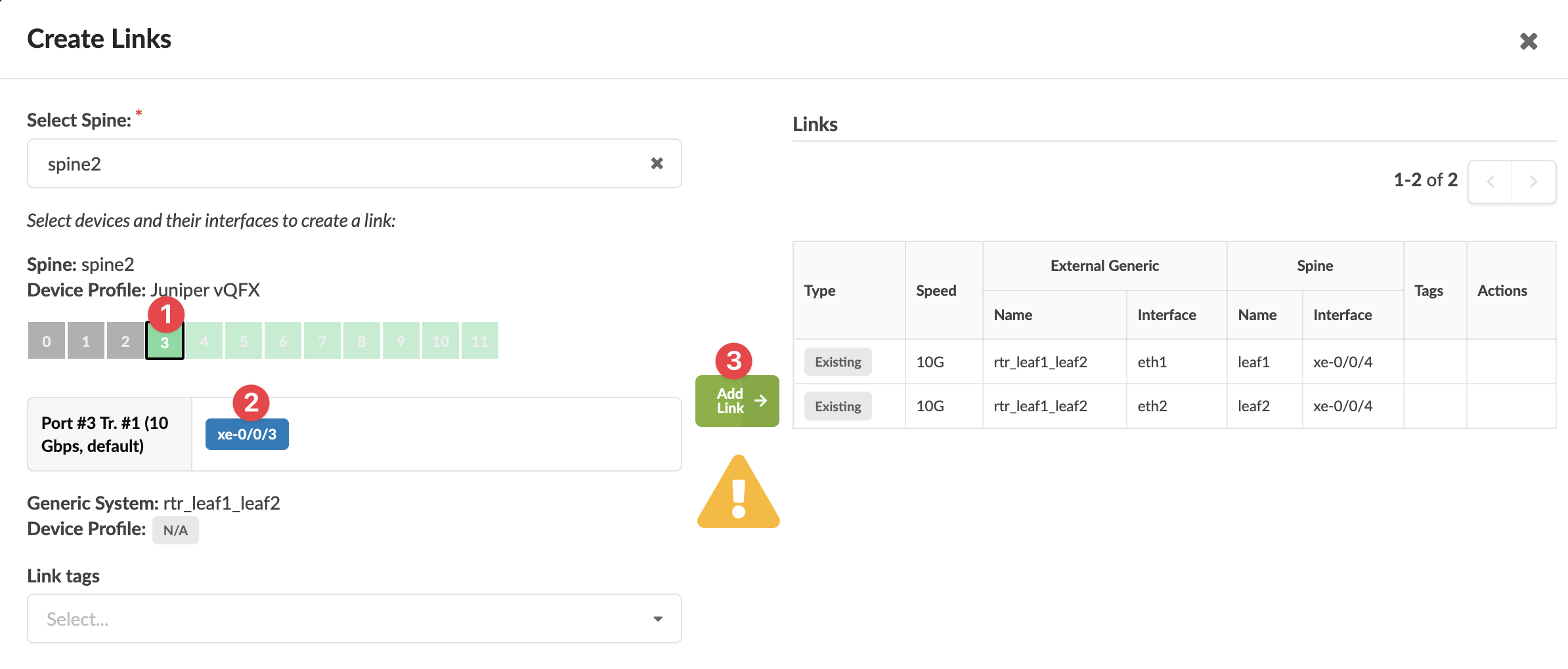
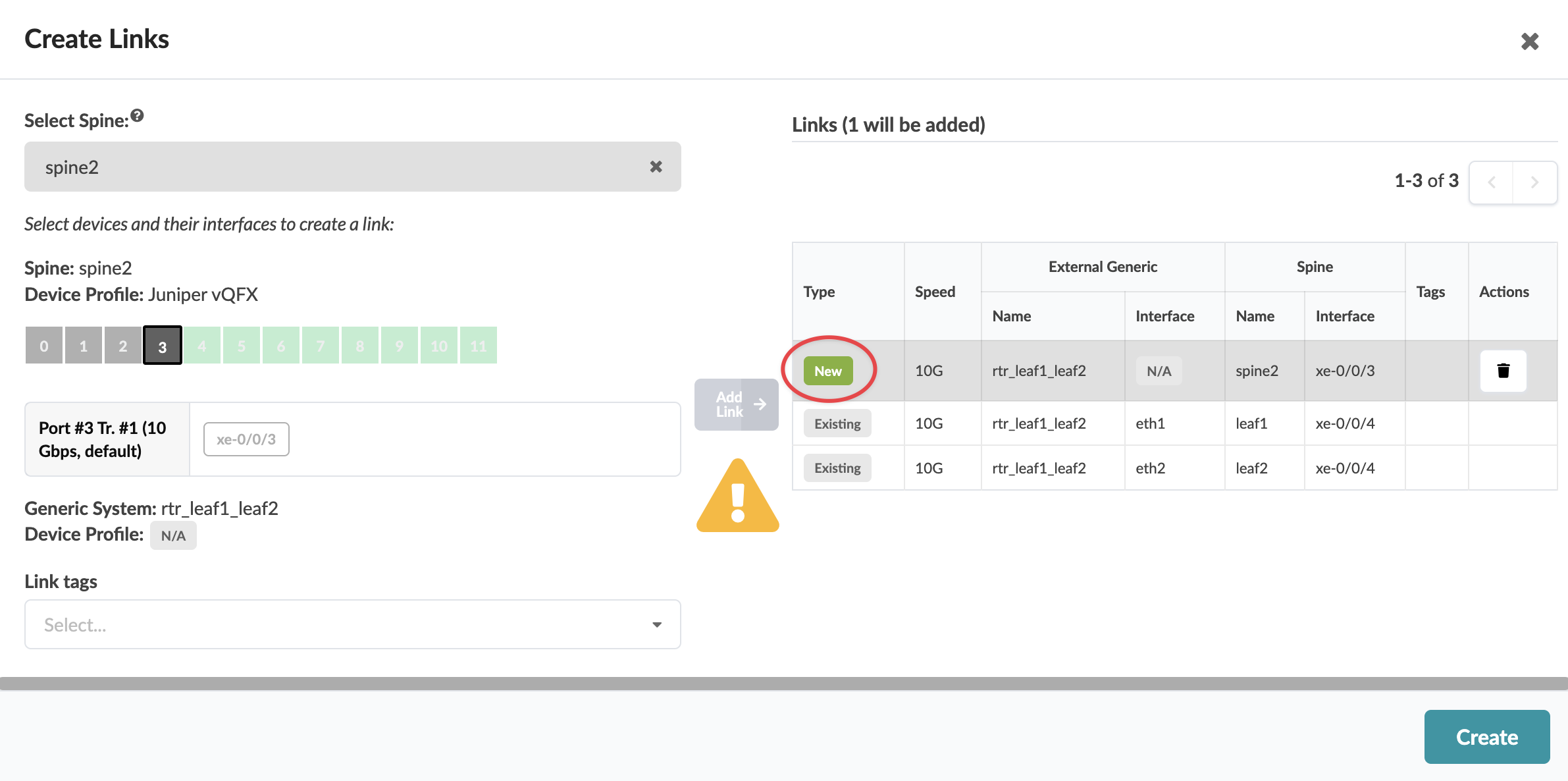
    User interface for creating network links with options to select spine device spine2, port xe-0/0/3, add link, and assign tags. Table shows existing links with type, speed, external device details, spine device details, tags, and actions.
    The gray Add Link button turns green.
  6. Click Add Link.
    The link is added to the link table.
  7. Click CreateCreate Links interface for network configuration; spine device spine2 with Juniper vQFX profile. Port xe-0/0/3 at 10 Gbps selected. External device rtr_leaf1_leaf2 linked. New link highlighted in table. Warning triangle indicates issue. Trash icon available for deletion. Create button at bottom right.
The change is staged and you're returned to the Topology view.

When you're ready to activate your changes, go to the Uncommitted tab to review and commit (or discard) your changes.