Add Links to Internal Generic System

To add links to an internal generic system using the GUI:
  1. From the blueprint, navigate to Staged > Physical > Topology and select a node that can connect to a generic system.
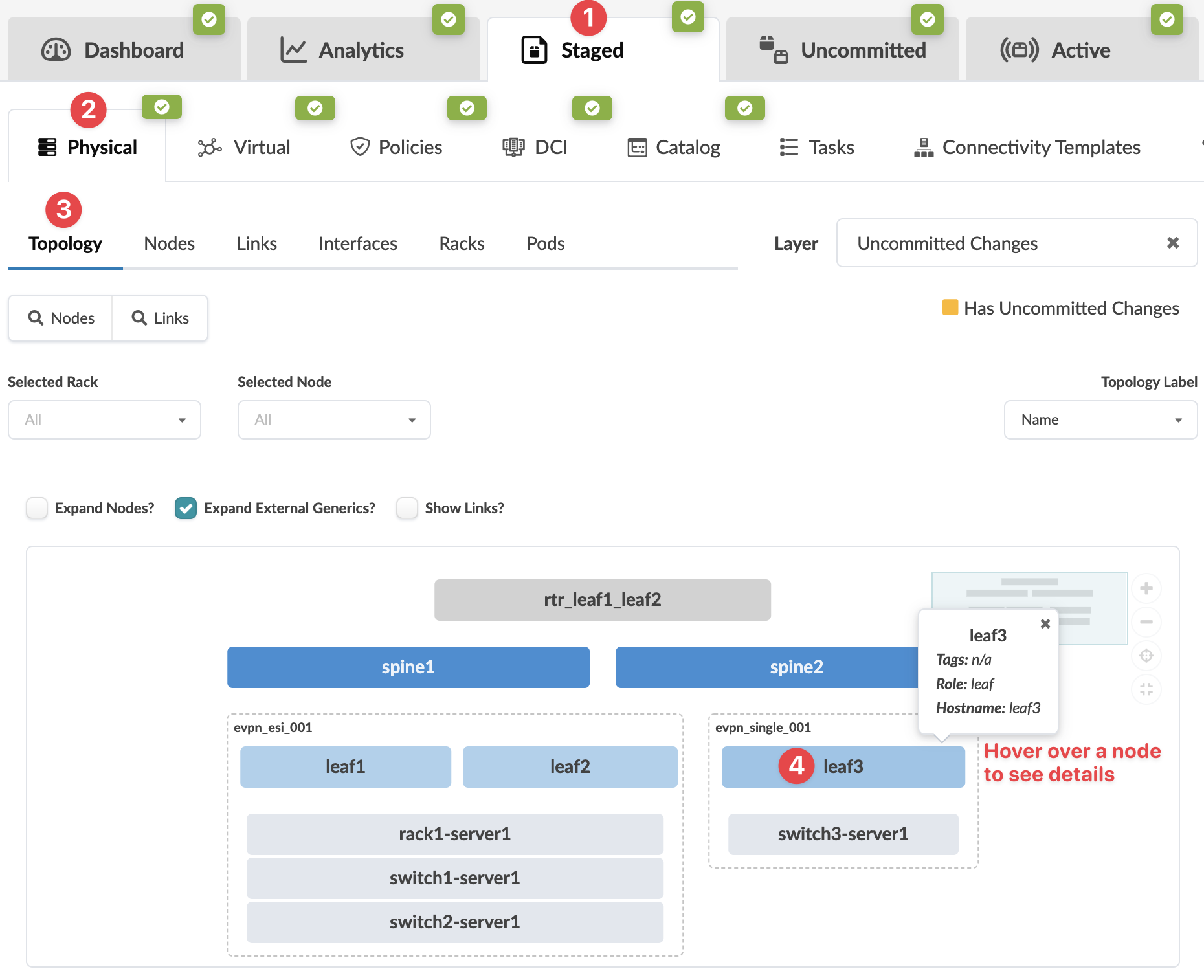
    Network management interface with topology view showing nodes and devices. Tabs for Dashboard, Analytics, and network states. Spine and leaf switches with connected servers. Options for physical and virtual management.
    The Topology view of the selection appears.
  2. Select the node check box to see the operations available for that node (and that you have permissions for).
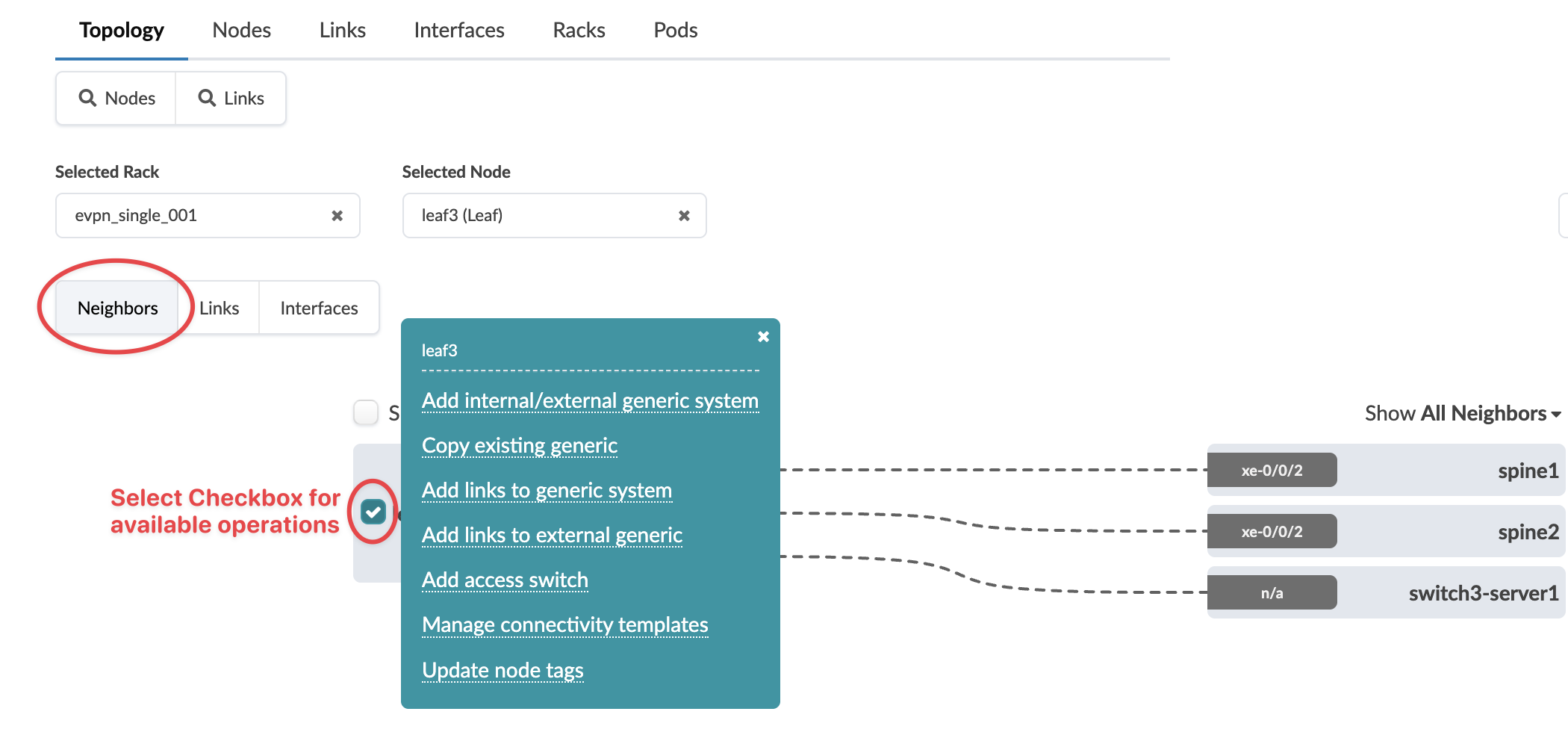
    GUI for network topology management with tabs: Topology, Nodes, Links, Interfaces, Racks, Pods. Selected Rack: evpn_single_001, Node: leaf3. Connections from leaf3 to neighbors: spine1, spine2, switch3-server1. Operations menu available with options like Add internal/external system, Copy existing, Manage templates. Dashed lines show links, interfaces labeled xe-0/0/2. Dropdown: Show All Neighbors.
    Note:

    You can also get to the selection page from the Nodes view. From the blueprint, navigate to Staged > Physical > Nodes, click the node name in the table, then click the node name that appears at the top of the Selection panel (on the right side of the page).

  3. Click Add links to generic system
    The Create Links dialog opens.
  4. Select an available port and transformation, then select the generic system to link to from the drop-down menu .
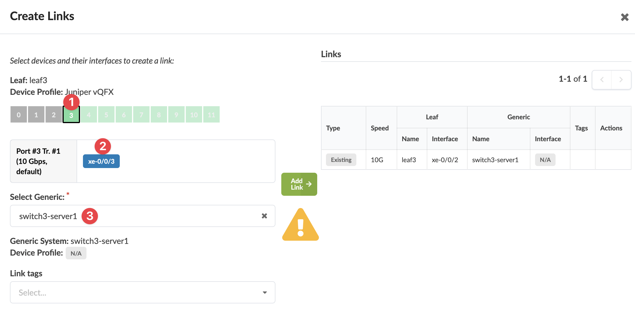
    Network configuration interface showing device leaf3 with Juniper vQFX profile. Port xe-0/0/3 at 10 Gbps selected. Dropdown for generic device switch3-server1. Add Link button and warning icon present. Existing links table displayed.
    The gray Add Link button turns green.
  5. Click Add Link.
    The link is added to the link table.
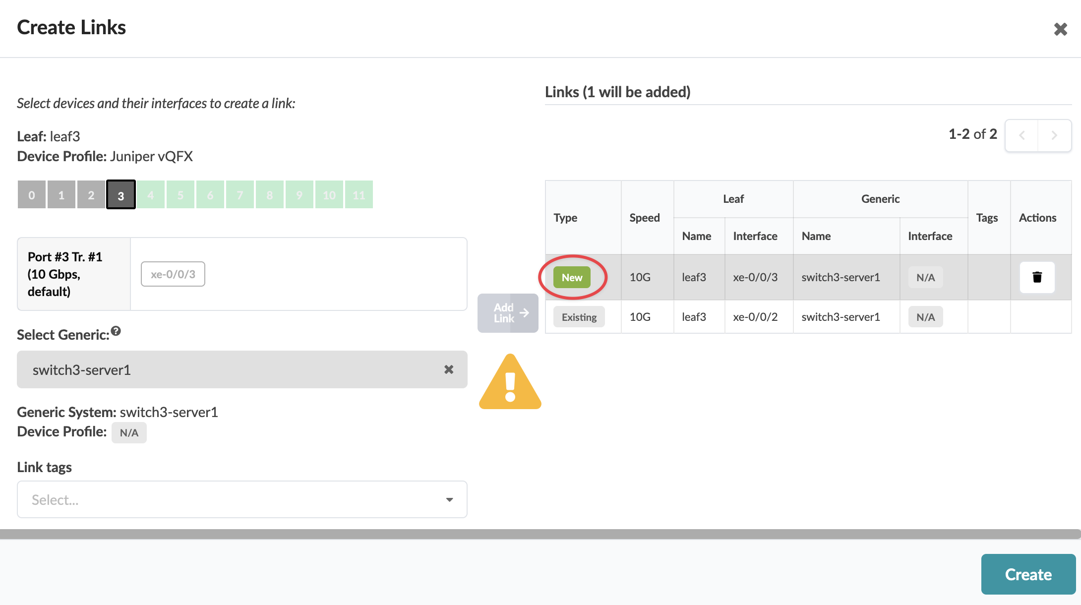
  6. Click Create.
    User interface for creating network links with title Create Links, device leaf3 with Juniper vQFX profile, selected port xe-0/0/3 at 10 Gbps, generic system switch3-server1, links table showing details, warning icon displayed, and actions Add Link, Create, and delete link available.

The new link is staged and you're returned to the Topology view.
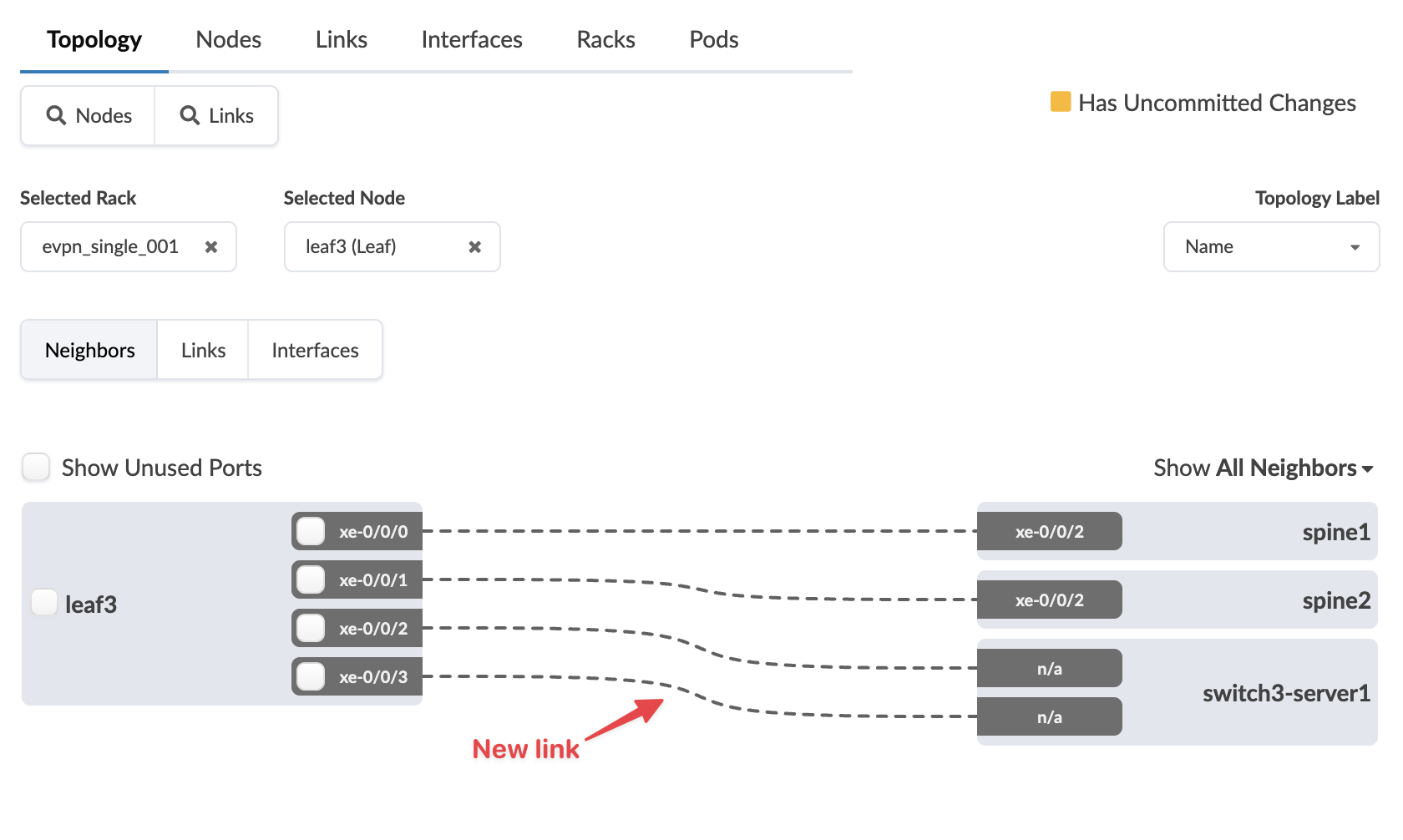
Network topology interface showing rack evpn_single_001 and node leaf3 with four ports xe-0/0/0 to xe-0/0/3. Connections include spine1 and spine2 via xe-0/0/2, switch3-server1 via n/a ports, and a new link marked by a red arrow. Neighbors view displayed with options for nodes, links, interfaces, racks, and pods. Features include a checkbox for unused ports, yellow indicator for uncommitted changes, and dropdown for topology labels set to Name.

When you're ready to activate your changes, go to the Uncommitted tab to review and commit (or discard) your changes.