Add Leaf Peer Links
If your platform does not support it, do not attempt to create leaf peer links. Currently, Junos devices do not support any peer links, and SONiC devices do not support L3 peer links.
To add leaf peer links using the GUI
-
From the blueprint, navigate to Staged > Physical >
Topology and select the MLAG member that needs a peer link.
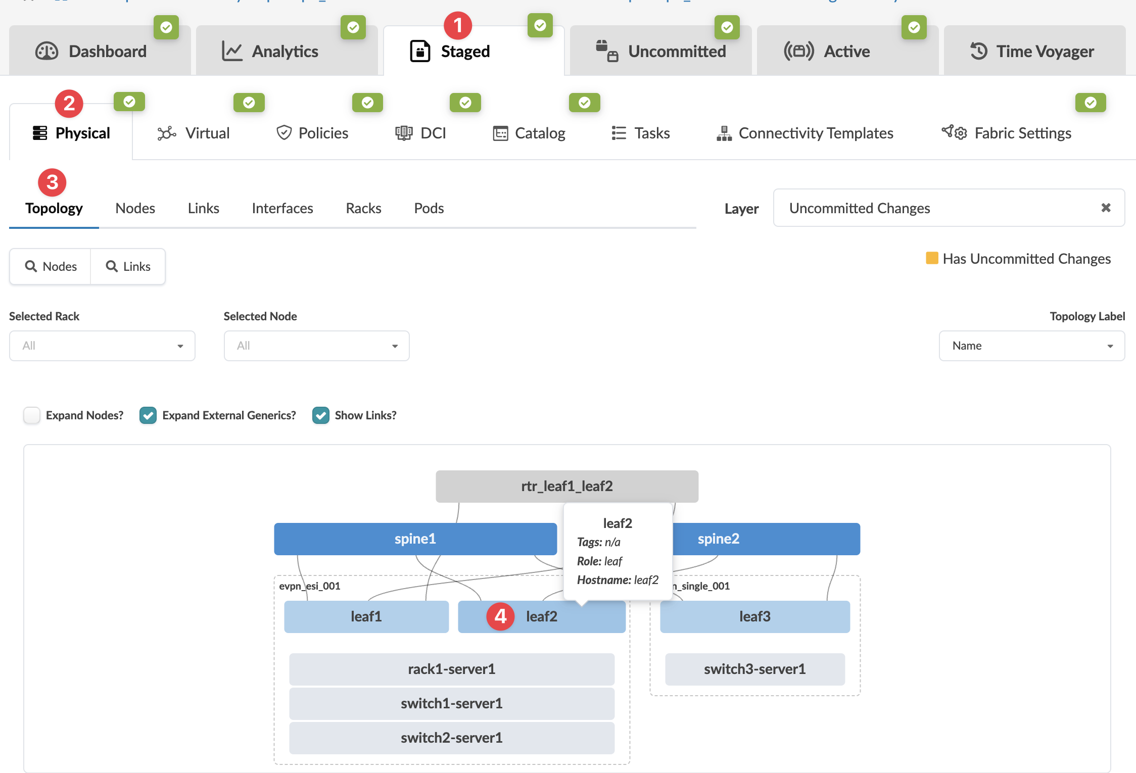 The Topology selection view of appears.
 -
Select the node check box to see the operations available for that node (and that you
have permissions for).
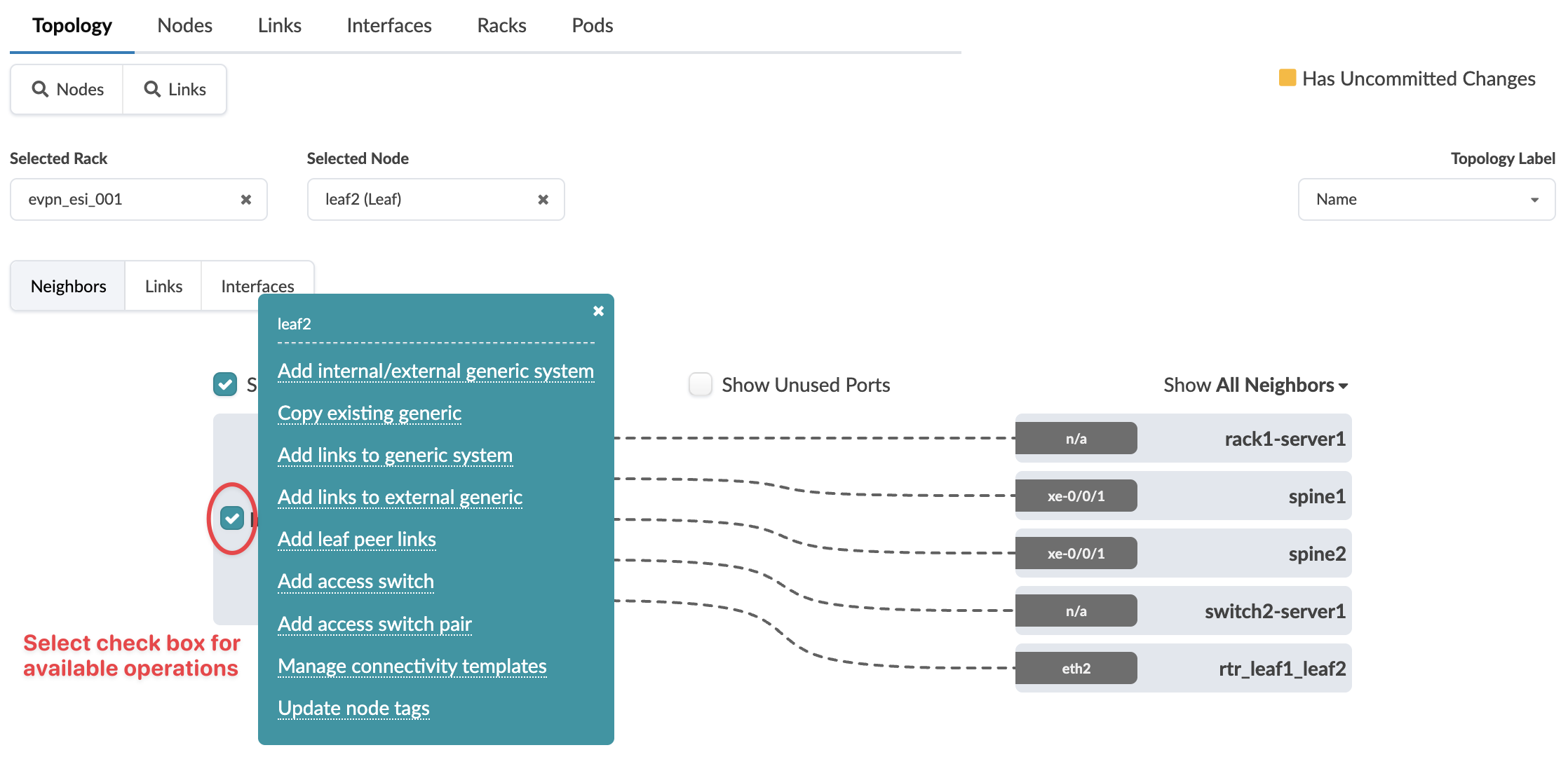 Note:
Note:You can also get to the selection page from the Nodes view. From the blueprint, navigate to Staged > Physical > Nodes, click the node name in the table, then click the node name that appears at the top of the Selection panel (on the right side of the page).
-
Select the link type (peer link, L3 peer link) and an available port and transformation
for each leaf member. (Only unused ports are selectable.)
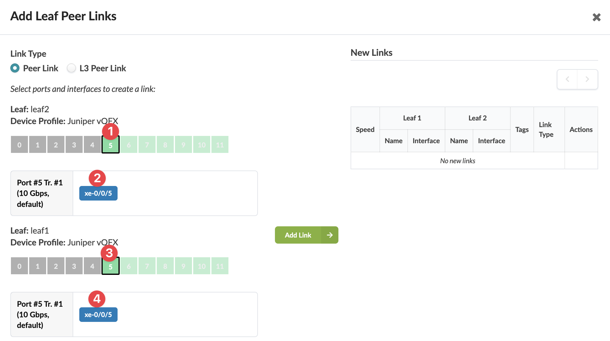 The gray Add Link button turns green.
The new link is staged and you're returned to the
Topology view. (BGP session is added as applicable.)
When you're ready to activate your changes, go to the Uncommitted tab to review and commit (or discard) your changes.