Form LAG
You can form a LAG using the GUI.
When you form a LAG, it inherits any connectivity templates assigned on the individual links. The LAG is created, but LACP configuration won't be pushed to the device until connectivity templates are applied. When you form a LAG, it inherits any connectivity templates assigned on the individual links.
To form a LAG using the GUI:
-
From the blueprint, navigate to Staged > Physical >
Topology and select the node to add as a member of a LAG. In our example,
we've selected leaf3.
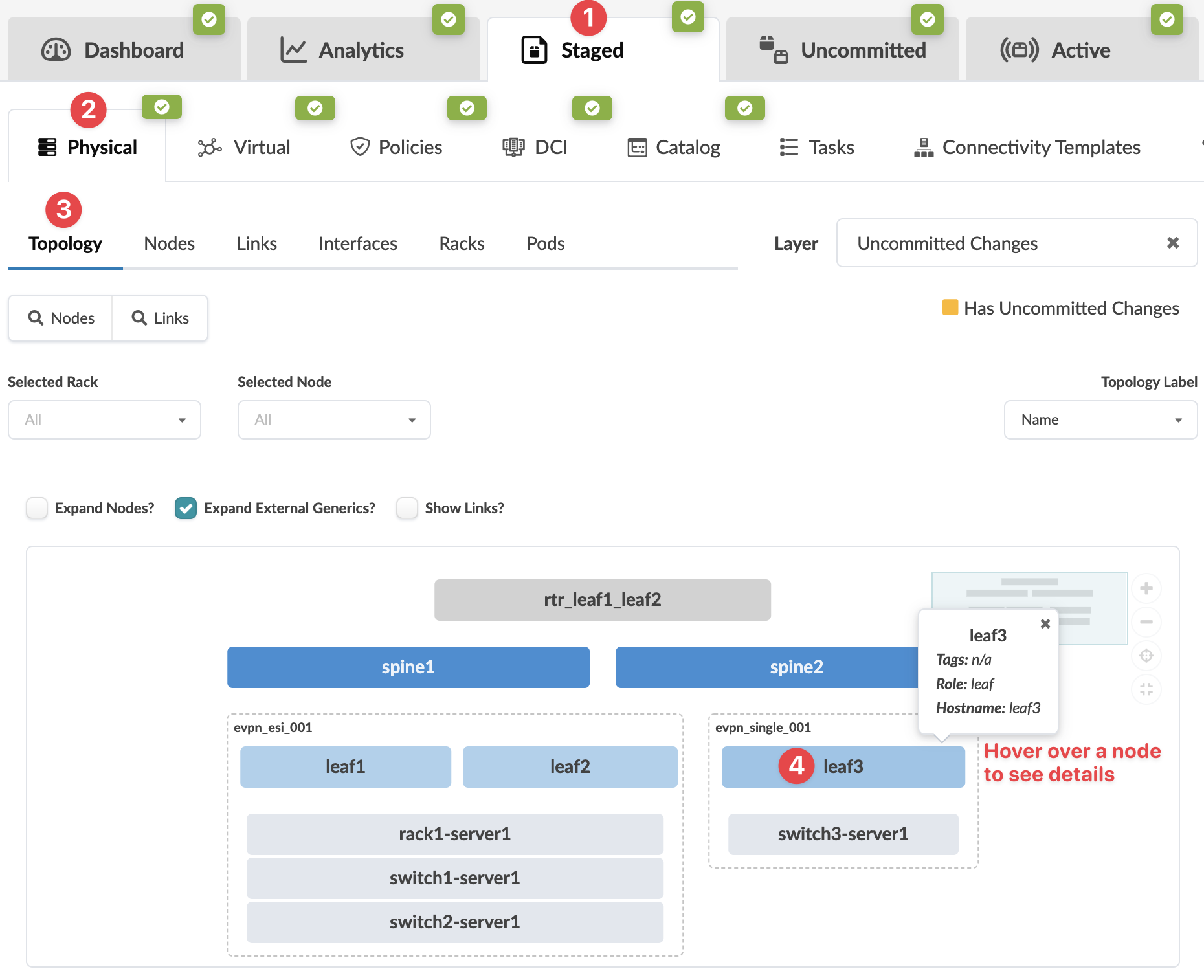 The Topology selection view appears.
 -
From the Neighbors view (default view), select the interface check box to see
the operations available for that link (and that you have permissions for).
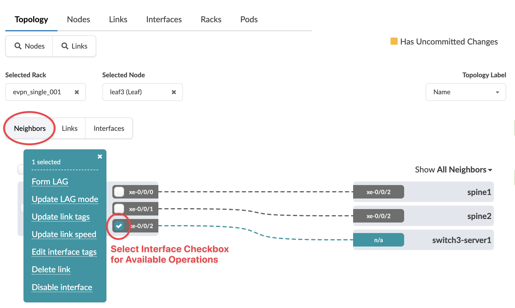
-
Select the LAG mode:
- LACP (Active) - actively advertises LACP BPDU even when neighbors do not.
- LACP (Passive) - doesn't generate LACP BPDU until it sees one from a neighbor.
- Static LAG (no LACP) - Static LAGs don't participate in LACP and will conditionally operate in forwarding mode.
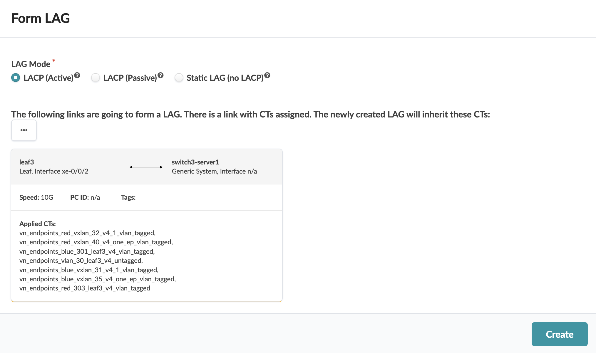
The changes are staged and you're returned to the Topology selection view
When you're ready to activate your changes, go to the Uncommitted tab to review and commit (or discard) your changes.