Maintain the QFX5241-32OD-DO-T1 Cooling System
The fan modules in the QFX5241-32OD-T1 switch are hot-removable and hot-insertable Field-Replaceable Units (FRUs), allowing them to be removed and installed without powering down the switch or disrupting normal switching operations. Fan modules can also be replaced when the switch is powered off and off-rack.
The ORv3-compliant QFX5241-32OD-DO-T1 switches support the replacement of field replaceable units (FRUs) such as fans. For more information on the fan module, redundancy support, and airflow, see QFX5241-32OD Cooling System. The fan can be replaced at the following operational states:
- On rack (fully installed)—You can replace the fan while the switch is installed on the ORv3 rack. The switch-tray assembly is powered by the busbar in this state and fully operational.
- Off rack, on tray—You can replace the PSU and fan after the switch is removed from the ORv3 rack, but still attached to the tray. The switch is not operational in this state.
Remove a Fan Module from QFX5241-32OD-DO-T1 Switch While Operational
We ship the QFX5241-32OD-T1 switch from the factory with seven fan modules.
Before you remove a fan module from QFX5241-32OD-T1 switch, ensure that you have taken the necessary precautions to prevent electrostatic discharge (ESD) damage.
To ensure proper airflow, keep a failed fan module in place until you have a replacement fan module at hand. Do not run the device with an open fan tray slot for an extended amount of time.
Ensure that you have the following parts and tools available to remove the fan module from QFX5241-32OD-T1 switch:
-
ESD grounding strap
-
Antistatic bag or an antistatic mat
-
Replacement fan module
Based on the ambient temperature, the time allowed to replace a fan module in the chassis varies.
|
Ambient Temperature (°C) |
Duration |
|---|---|
|
40 |
2 minutes |
-
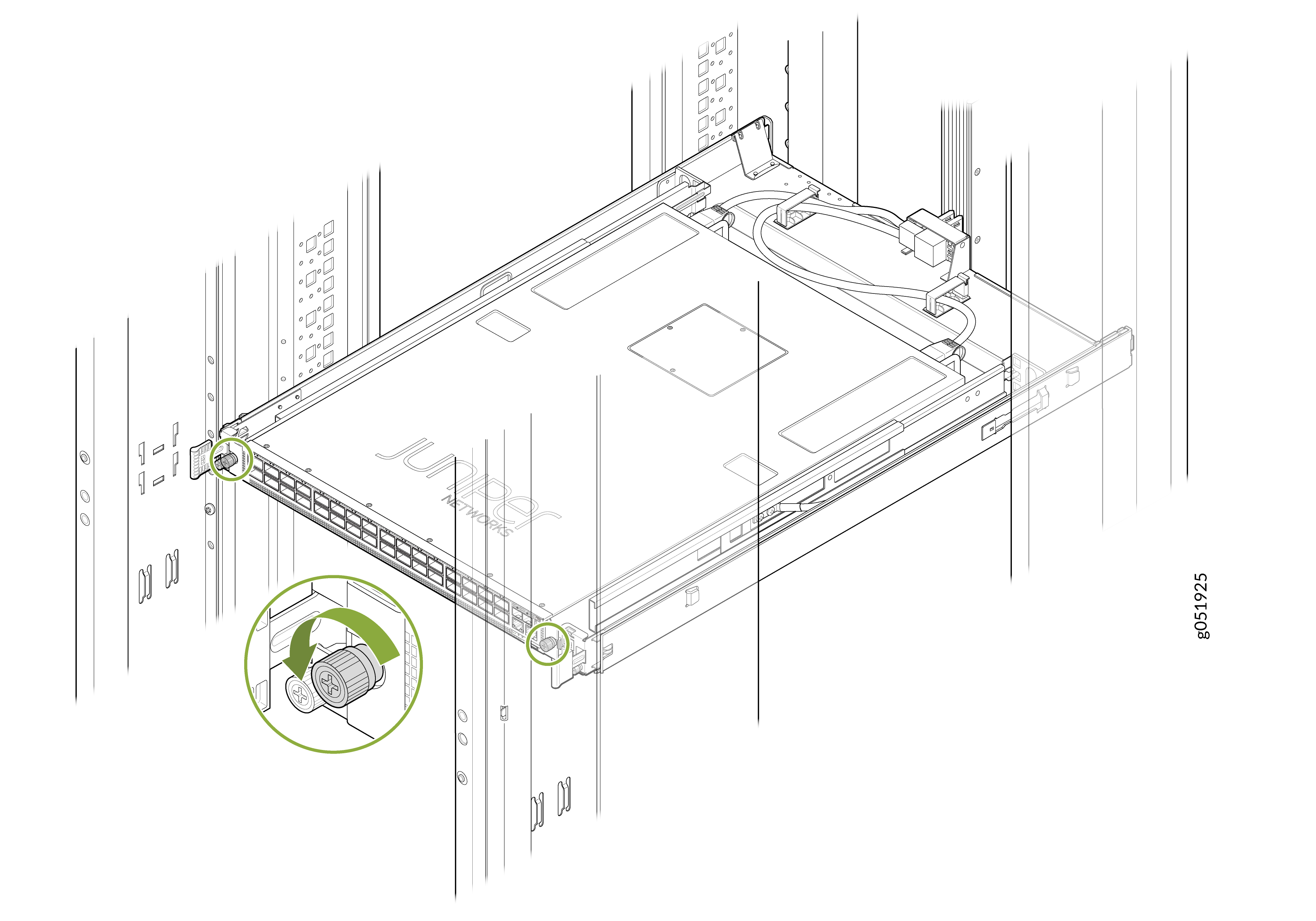
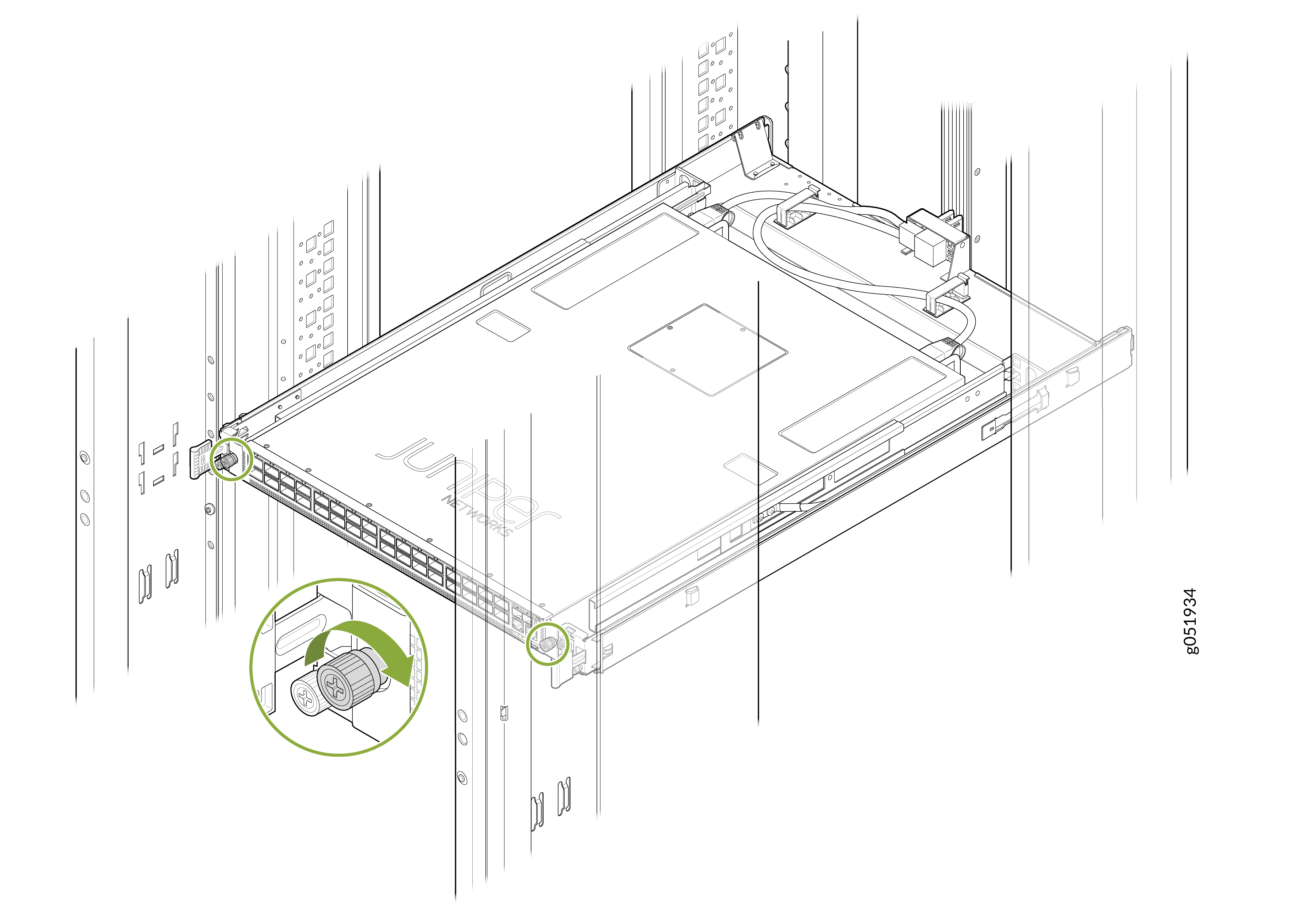
Loosen and remove the thumbscrews on both sides of the chassis to unfasten
the switch from the switch-tray assembly.
Figure 1: Remove the Thumbscrews
-
Slide the switch chassis toward the front until the fan module is
accessible.
Note: You must slide the chassis to the front in the switch-tray assembly by approximately 150 mm to ensure that the fans are accessible.Figure 2: Slide the Switch

-
Grasp the handle on the fan module and squeeze the outside of the handle to
release the module.
Figure 3: Remove the Fan Module from QFX5241-32OD-T1 Switch While Operational
 Warning:
To avoid injury, do not touch the fan with your hands or any tools as you slide the fan module out of the chassis—the fan might still be running.
When you remove a fan module, the CLI message Fan/Blower is Absent is logged in the system log, and the system raises a major alarm.
Remove a Fan Module from QFX5241-32OD-DO-T1 Switch While Off-Rack
We ship the QFX5241-32OD-T1 switch from the factory with seven fan modules.
Before you remove a fan module from QFX5241-32OD-T1 switch, ensure that you have taken the necessary precautions to prevent electrostatic discharge (ESD) damage.
Ensure that you have the following parts and tools available to remove the fan module from QFX5241-32OD-T1 switch:
-
ESD grounding strap
-
Antistatic bag or an antistatic mat
-
Replacement fan module
-
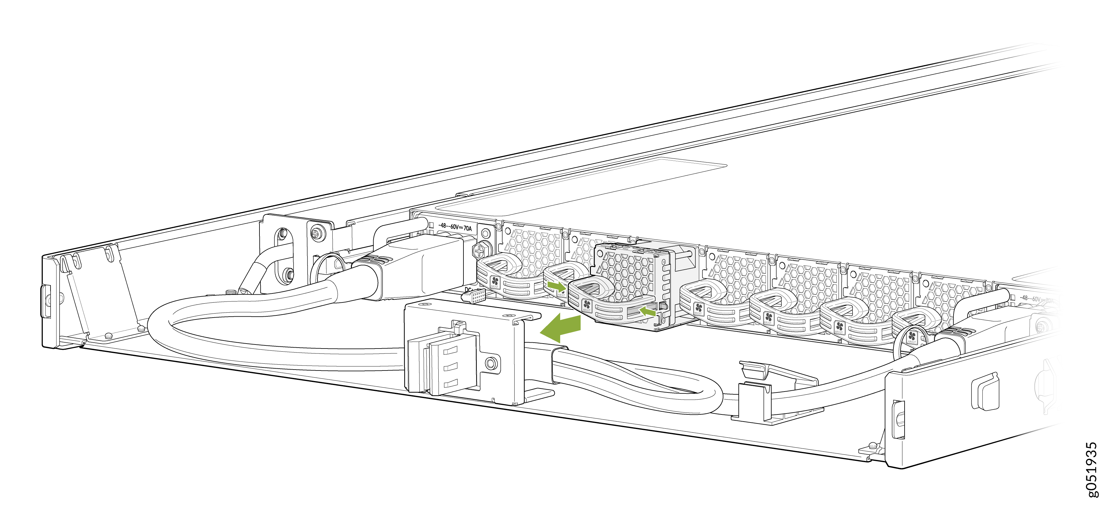
Grasp the handle on the fan module and squeeze the outside of the handle to
release the module.
Figure 4: Remove the Fan Module from QFX5241-32OD-T1 Switch While Off-Rack
When you remove a fan module, the CLI message Fan/Blower is Absent is logged in the system log, and the system raises a major alarm.
Install a Fan Module in QFX5241-32OD-DO-T1 Switches While Operational
Before you install a fan module in QFX5241-32OD-T1 switch, ensure that you have taken the necessary precautions to prevent ESD damage.
The fan modules in the QFX5241-32OD-T1 switch are hot-removable and hot-insertable FRUs. You can remove and replace them without powering off the switch or disrupting switch functions.
To ensure proper airflow, keep a failed fan module in place until you have a replacement fan module at hand. Do not run the device with an open fan tray slot for an extended amount of time.
For the QFX5241-32OD-T1 switch, the fan module provides AFO or front-to-back airflow.
To install a fan module in QFX5241-32OD-T1 switch:
-
Loosen and remove the thumbscrews on both sides of the chassis to unfasten
the switch from the switch-tray assembly.
Figure 5: Remove the Thumbscrews
-
Slide the switch chassis toward the front until the fan module is
accessible.
Note: You must slide the chassis to the front in the switch-tray assembly by approximately 150 mm to ensure that the fans are accessible.Figure 6: Slide the Switch
-
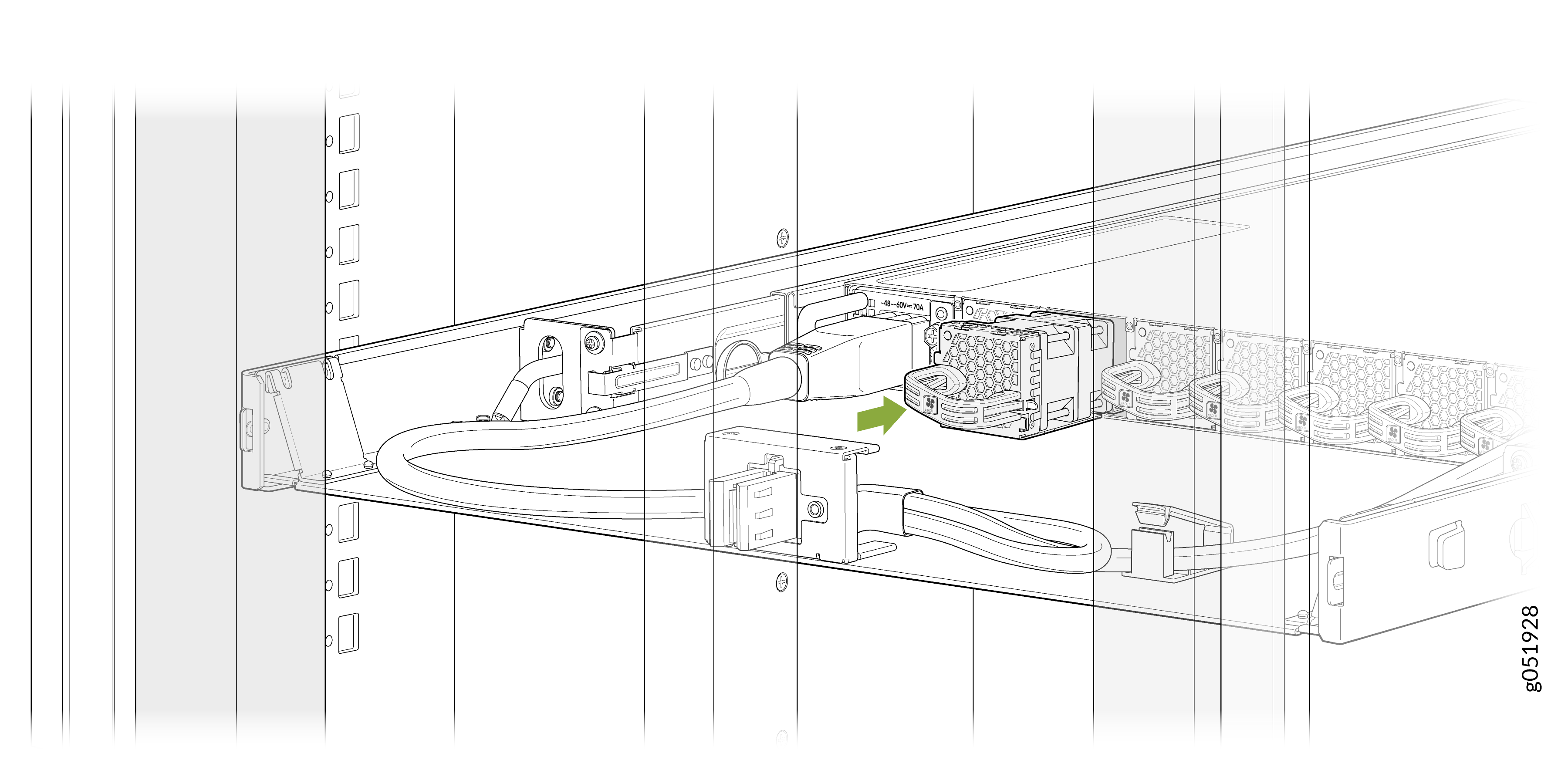
With the chassis tray slid toward the front, align the module with the open
slot and slide it in until it is fully seated.
Figure 7: Install a Fan Module in a QFX5241-32OD-T1 Switch While Operational
 CAUTION:
Damage can occur if you attempt to install a fan module into a chassis with a different airflow direction. Compare the switch product variant with the airflow marking on the handle to ensure that you are installing a fan module with the same airflow direction as the chassis. The fan modules are designed so that they can only be inserted into the QFX5241-32OD-T1 product variant that supports the same airflow type. See Maintain the QFX5241-32OD Power System for more information.
-
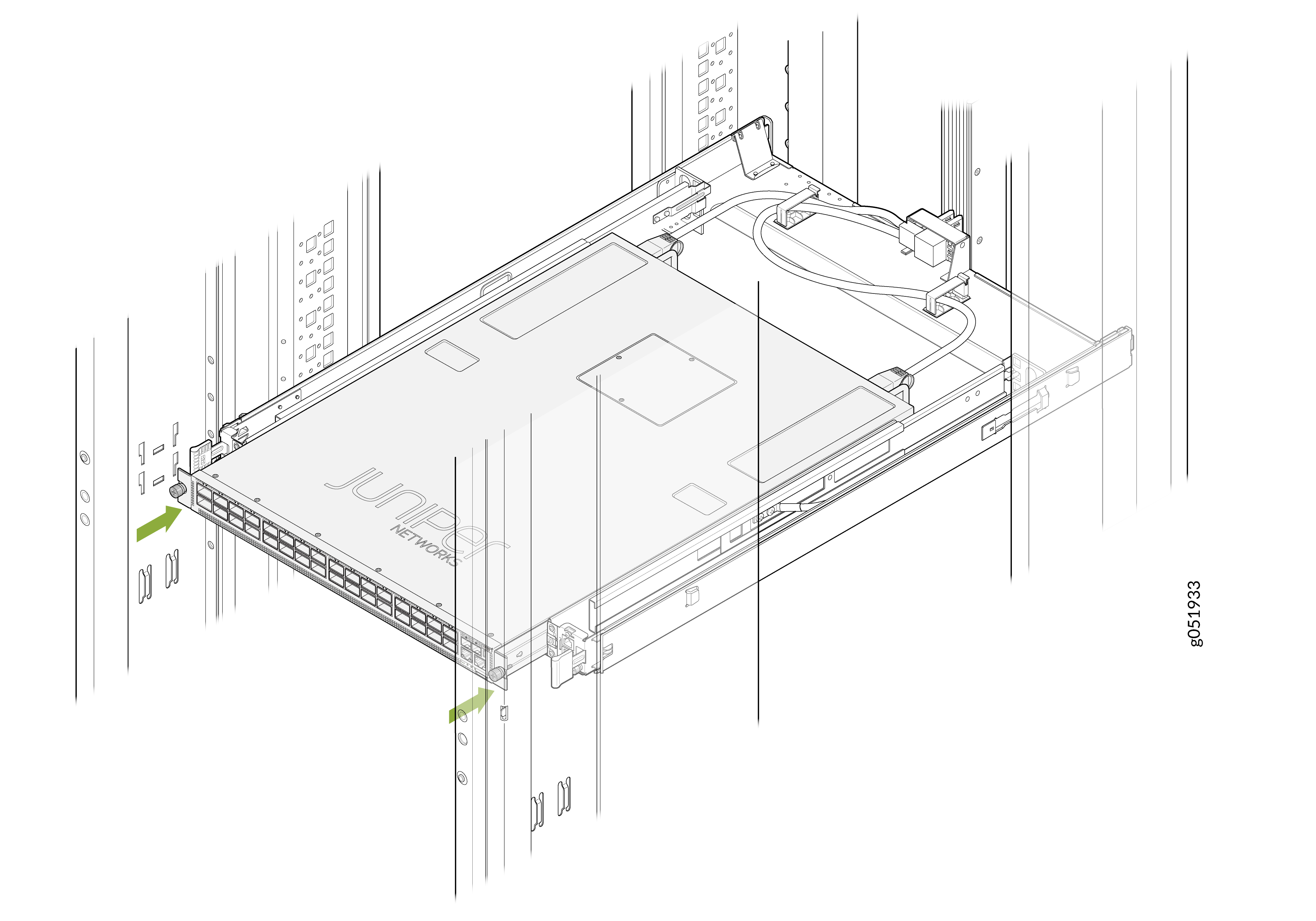
Slide the switch-tray assembly back into place.
Figure 8: Slide the Switch-Tray into Position
-
Tighten the thumbscrews on both sides of the chassis.
Figure 9: Tighten the Thumbscrews
Install a Fan Module in QFX5241-32OD-DO-T1 Switches While Off-Rack
Before you install a fan module in QFX5241-32OD-T1 switch, ensure that you have taken the necessary precautions to prevent ESD damage.
For the QFX5241-32OD-T1 switch, the fan module provides AFO or front-to-back airflow.
To install a fan module in QFX5241-32OD-T1 switch:
-
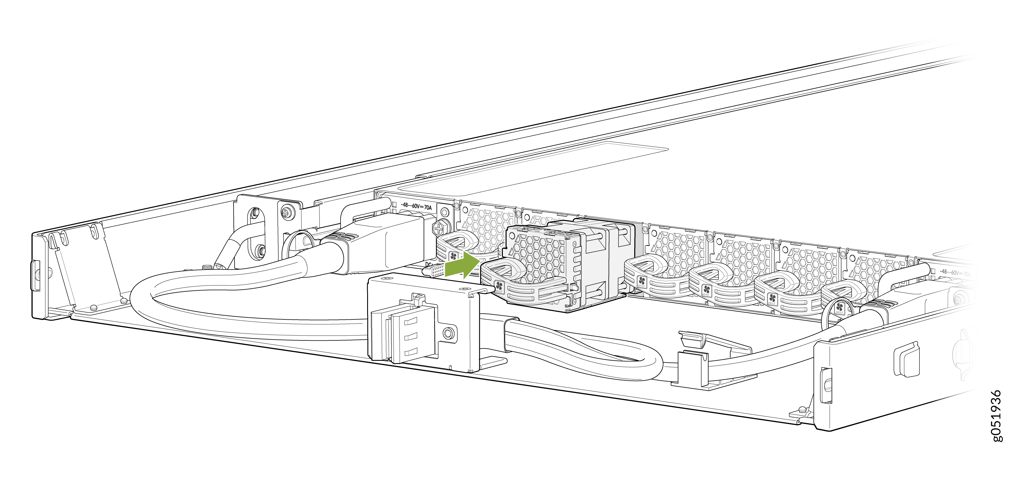
Align the module with the open slot and slide it in until it is fully
seated.
Figure 10: Install a Fan Module in the QFX5241-32OD-T1 Switch While Off-Rack
 CAUTION:
Damage can occur if you attempt to install a fan module into a chassis with a different airflow direction. Compare the switch product variant with the airflow marking on the handle to ensure that you are installing a fan module with the same airflow direction as the chassis. The fan modules are designed so that they can only be inserted into the QFX5241-32OD-T1 product variant that supports the same airflow type. See Maintain the QFX5241-32OD Power System for more information.