PTX12012 Power System
The PTX12012 power system includes AC/HVAC/HVDC and DC power supply modules and related power cords and cables.
The PTX12012 is powered by 36 power supply modules (PSMs).
The router supports the following PSMs:
-
3.7 kilowatt (kW) AC/HVAC/HVDC PSM (model number: JNP-PWR-3K-AC)
-
3 kW AC/HVAC/HVDC PSM (model number: JNP-PWR3K20A-AC)
-
DC PSM (model number: JNP-PWR-3K-DC)
The PSMs are hot-insertable and hot-removable field-replaceable units (FRUs). You can install the PSMs in the PSM slots on the rear panel of the chassis.
Do not install AC/HVAC/HVDC and DC PSMs in the same chassis.
Power Shelf
The power shelf provides the housing and electrical connections for the PSMs. It provides point-to-point connections for power and signal and DC power and connections between the PSMs and the PTX12012 chassis.
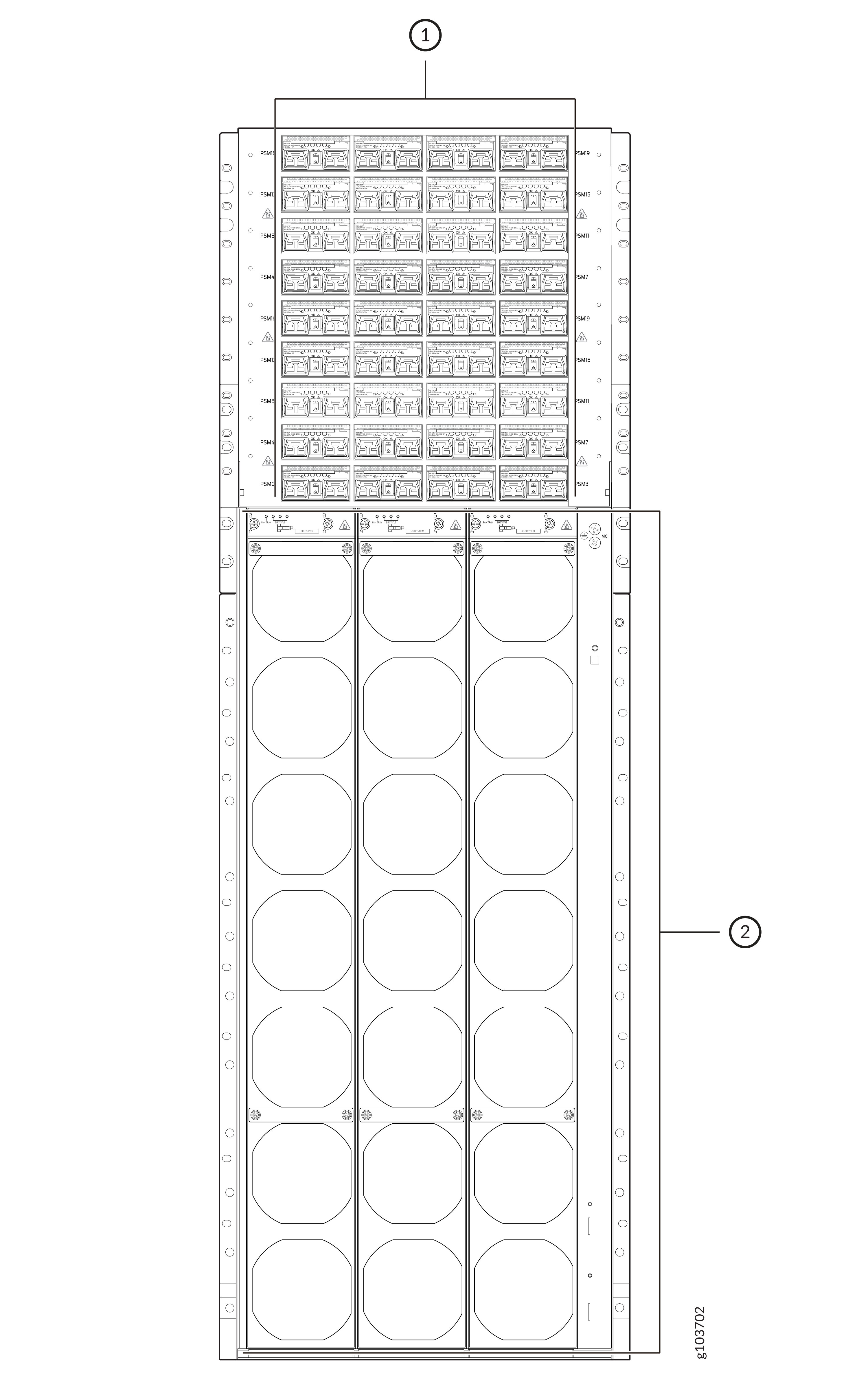
1 — Power shelf | 2 — Fan trays |
Table 1 shows the physical specifications of the power shelf.
|
Specification |
Values |
|---|---|
|
Number of PSMs that the power shelf can hold |
36 |
|
PSM numbering |
0 through 35 |
|
Height |
17.5 in. (44.45 cm) |
|
Width |
18.9 in. (48 cm) |
|
Depth |
32.75 in. (83.2 cm) |
|
Weight |
209 lb (95 kg) |
JNP-PWR-3K-AC PSM
Learn about the JNP-PWR-3K-AC PSM used on the PTX12012 and its specifications.
The JNP-PWR-3K-AC PSM supports AC, high-voltage AC (HVAC), or high-voltage DC (HVDC) input. The PSM automatically detects whether there is AC, HVAC, or HVDC input and manages the power accordingly. The PSM provides 3700-watt (W) DC output.

1 — Handle | 3 — AC/HVAC/HVDC inlets |
2 — Ejector lever | 4 — Power switch |
Each PSM has its own built-in fan and is cooled by its own internal cooling system. Hot air exhausts from the rear of the chassis.
Each PSM has two independent 24-Amperes (A) rated AC/HVAC/HVDC inlets on the faceplate. Though each inlet provides sufficient input power to provide full output, always connect both inlets to dedicated AC/HVAC/HVDC power sources to provide redundancy.
Each JNP-PWR-3K-AC PSM has a handle, an ejector lever, a power switch with international markings for on (|) and off (O), two AC/HVAC/HVDC inlets, and four status LEDs on the faceplate.
Table 2 shows the physical specifications of the PSM.
|
Specification |
Values |
|---|---|
|
Height |
1.6 in. (4 cm) |
|
Width |
3.2 in. (8 cm) |
|
Depth |
21 in. (53.3 cm) |
|
Weight |
6.8 lb (3.1 kg) |
JNP-PWR-3K-AC operates within the AC/HVAC/HVDC input voltage range listed in Table 3.
|
Parameter |
Minimum |
Rated |
Maximum |
|---|---|---|---|
|
Input voltage—AC/HVAC |
180 VAC |
200–277 VAC |
305 VAC |
|
Frequency for input—AC/HVAC |
47 Hz |
50-60 Hz |
63 Hz |
|
Input voltage—HVDC |
190 VDC |
240–380 VDC |
410 VDC |
JNP-PWR-3K-AC PSM LEDs
Learn about the LEDs on the JNP-PWR-3K-AC PSM used on the PTX12012.
The JNP-PWR-3K-AC PSM has four LEDs on its faceplate: 0 (INP0), 1 (INP1), OK (Power OK), and ! (Fault). These LEDs display information about the status of the PSM.

1 — 0 (INP0) LED | 3 — ! (Fault) LED |
2 — OK (Power OK) LED | 4 — 1 (INP1) LED |
|
LED |
Color |
State |
Description |
|---|---|---|---|
|
0 (INP0) and 1 (INP1) |
Green |
Solid |
The input power is within normal operating range. |
|
Amber |
Blinking |
The input power is not within normal operating range. |
|
|
None |
Unlit |
The PSM is switched off; the voltage is zero. |
|
|
OK (Power OK) |
Green |
Solid |
The output power is within normal operating range. |
|
Amber |
Blinking |
The output power is not within normal operating range. |
|
|
! (Fault) |
Red |
Solid |
The PSM has failed; you must replace it. |
|
None |
Unlit |
The PSM is functioning normally. |
You can get additional information about the status of the PSMs by using the show chassis power command.
JNP-PWR-3K-AC PSM Power Cord Specifications
Learn about the power cords for the JNP-PWR-3K-AC PSM used on the PTX12012 and their specifications.
Table 5 lists the specifications of the AC/HVAC power cord provided for each country or region.
|
Power Cord Type |
Locale |
Cord Set Rating |
Plug Standards |
Connector |
Spare Juniper Model Number |
|---|---|---|---|---|---|
|
HVDC power cord |
Any |
30-A, 400 VAC |
No plug used, only bare wire |
Anderson/straight to bare wire |
CBL-PWR2-BARE |
|
AC/HVAC power cord |
Continental Europe |
30-A 250 VAC |
IEC 332P6 |
Anderson/straight to IEC 332P6 |
CBL-PWR2-332P6W |
|
North America |
30-A 250 VAC |
IEC 330P6 |
Anderson/straight to IEC 330P6 |
CBL-PWR2-330P6W |
JNP-PWR3K20A-AC PSM
Learn about the JNP-PWR3K20A-AC PSM used on the PTX12012 and its specifications.
The JNP-PWR3K20A-AC PSM supports AC, high-voltage AC (HVAC), or high-voltage DC (HVDC) input. The PSM automatically detects whether there is AC, HVAC, or HVDC input and manages the power accordingly. The PSM provides 3000-watt (W) DC output.
1 — Handle | 3 — AC/HVAC/HVDC inlets |
2 — Ejector lever | 4 — Power switch |
Each PSM has its own built-in fan and is cooled by its own internal cooling system. Hot air exhausts from the rear of the chassis.
Each PSM has two independent 16-Amperes (A) rated AC/HVAC/HVDC inlets on the faceplate. Though each inlet provides sufficient input power to provide full output, always connect both inlets to dedicated AC/HVAC/HVDC power sources to provide redundancy.
Each JNP-PWR3K20A-AC PSM has a handle, an ejector lever, a power switch with international markings for on (|) and off (O), two AC/HVAC/HVDC inlets, and four status LEDs on the faceplate.
Table 6 shows the physical specifications of the AC/HVAC/HVDC PSM.
|
Specification |
Values |
|---|---|
|
Height |
1.6 in. (4 cm) |
|
Width |
3.2 in. (8 cm) |
|
Depth |
21 in. (53.3 cm) |
|
Weight |
6.8 lb (3.1 kg) |
JNP-PWR3K20A-AC operates within the AC/HVAC/HVDC input voltage range listed in Table 7.
|
Parameter |
Minimum |
Rated |
Maximum |
|---|---|---|---|
|
Input voltage—AC/HVAC |
180 VAC |
200–277 VAC |
305 VAC |
|
Frequency for input—AC/HVAC |
47 Hz |
50-60 Hz |
63 Hz |
|
Input voltage—HVDC |
190 VDC |
240–380 VDC |
410 VDC |
JNP-PWR3K20A-AC PSM LEDs
Learn about the LEDs on the JNP-PWR3K20A-AC PSM used on the PTX12012.
The JNP-PWR3K20A-AC PSM has four LEDs on its faceplate: 0 (INP0), 1 (INP1), OK (Power OK), and ! (Fault). These LEDs display information about the status of the PSM.

1 — 0 (INP0) LED | 3 — ! (Fault) LED |
2 — OK (Power OK) LED | 4 — 1 (INP1) LED |
|
LED |
Color |
State |
Description |
|---|---|---|---|
|
0 (INP0) and 1 (INP1) |
Green |
Solid |
The input power is within normal operating range. |
|
Amber |
Blinking |
The input power is not within normal operating range. |
|
|
None |
Unlit |
The PSM is switched off; the voltage is zero. |
|
|
OK (Power OK) |
Green |
Solid |
The output power is within normal operating range. |
|
Amber |
Blinking |
The output power is not within normal operating range. |
|
|
! (Fault) |
Red |
Solid |
The PSM has failed; you must replace it. |
|
None |
Unlit |
The PSM is functioning normally. |
You can get additional information about the status of the PSMs by using the show chassis power command.
JNP-PWR3K20A-AC PSM Power Cord Specifications
Learn about the power cords for the JNP-PWR3K20A-AC PSM used on the PTX12012 and their specifications.
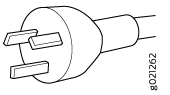
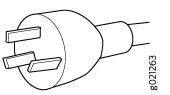
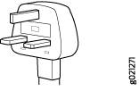
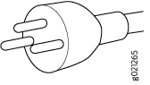
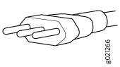
Table 9 lists the specifications of the AC/HVAC power cord provided for each country or region.
|
Locale |
Cord Set Rating |
Plug Standards |
Spare Juniper Model Number |
Graphic |
|---|---|---|---|---|
|
Argentina |
16 A, 250 VAC |
IRAM 2073 Type RA/3 |
CBL-JNP-SG4-AR |

|
|
Australia and New Zealand |
16 A, 250 VAC |
AS/NZS 4417 |
CBL-JNP-SG4-AU |
|
|
Brazil |
16 A, 250 VAC |
NBR 14136 Type BR/3 |
CBL-JNP-SG4-BR |

|
|
China |
16 A, 250 VAC |
GB2099 |
CBL-JNP-SG4-CH |
|
|
China, Europe, and Japan |
16 A, 250 VAC |
C20 to Anderson 3-5958p4 |
CBL-JNP-SG4-C20-CH |

|
|
Europe (except Italy, Switzerland, and United Kingdom) |
16 A, 250 VAC |
CEE 7/7 STRAIGHT |
CBL-JNP-SG4-EU |

|
|
Great Britain |
16 A, 250 VAC, |
BS1363 |
CBL-JNP-SG4-UK |
|
|
India |
16 A, 250 VAC |
SANS 164/1 |
CBL-JNP-SG4-SA |

|
|
Israel |
16 A, RA, 250 VAC |
SI 32/1971 Type IL/3G |
CBL-JNP-SG4-IL |
|
|
Italy |
16 A, 250 VAC |
CEI 23-16 |
CBL-JNP-SG4-IT |
|
|
Japan |
16 A, 250 VAC |
Nema L-20 |
CBL-JNP-SG4-JPL |

|
|
North America |
20 A, 250 VAC |
C20 to Anderson 3-5958p4 |
CBL-JNP-SG4-C20 |

|
|
North America |
20 A, 250 VAC |
Locking NEMA L6-20P |
CBL-JNP-SG4-US-L |
|
|
North America |
20 A, 250 VAC |
NEMA 6-20P |
CBL-JNP-SG4-US |

|
|
North America |
20 A, 277 V |
NEMA L7-20P |
CBL-JNP-SG4-HVAC |

|
|
South Africa |
16 A, 250 VAC |
SANS 164/1 |
CBL-JNP-SG4-SA |
|
|
Switzerland |
16 A, 250 VAC |
CEI 23-50 |
CBL-JNP-SG4-SZ |
|
Table 10 lists the specifications of the HVDC power cord.
|
Cord Set Rating |
Spare Juniper Model Number |
|---|---|
|
16 A, 400 HVDC |
CBL-PWR2-BARE |
JNP-PWR-3K-DC PSM
Learn about the JNP-PWR-3K-DC PSM used on the PTX12012 and its specifications.
The JNP-PWR-3K-DC PSM can operate with an input current of either 60 A or 80 A. The PSM has two independent pairs of DC input lugs (labeled Input 0, RTN, –48V/–60V and Input 1, RTN, –48V/–60V) on the faceplate of the PSM. Each inlet requires a dedicated DC power feed. You must always connect each of inlet the PSM to a dedicated DC power feed to provide redundancy. Only one power feed is operational at a time. You can configure the input using a dual inline package (DIP) switch on the PSM faceplate.

1 — Handle | 4 — Ejector lever |
2 — Power switch | 5 — Input tray handle |
3 — DIP switch |
Each PSM has its own built-in fan and is cooled by its own internal cooling system. Hot air exhausts from the rear of the chassis.
Each JNP-PWR-3K-DC PSM has a handle, a power switch with international markings for on (|) and off (O), a dual inline package (DIP) switch, an ejector lever, an input tray, and four status LEDs on the faceplate.
Table 11 shows the physical specifications of the DC PSM.
|
Specification |
Values |
|---|---|
|
Height |
1.6 in. (4 cm) |
|
Width |
3.2 in. (8 cm) |
|
Depth |
21 in. (53.3 cm) |
|
Weight |
5.1 lb (2.3 kg) |
Table 12 provides the specifications of the DC PSMs.
|
Item |
Specification |
|---|---|
|
Input voltage |
Rated operating voltage: –48 VDC |
|
Input current rating |
60 A |
JNP-PWR-3K-DC PSM LEDs
Learn about the LEDs on the JNP-PWR-3K-DC PSM used on the PTX12012.
The JNP-PWR-3K-DC PSM has four LEDs on its faceplate: 0 (INP0), 1 (INP1), OK (Power OK), and ! (Fault). These LEDs display information about the status of the PSM.

1 — 0 (INP0) LED | 3 — ! (Fault) LED |
2 — OK (Power OK) LED | 4 — 1 (INP1) LED |
|
LED |
Color |
State |
Description |
|---|---|---|---|
|
0 (INP0) and 1 (INP1) |
Green |
Solid |
The input power is within normal operating range. |
|
Yellow |
Blinking |
The input power is not within normal operating range. |
|
|
Unlit |
Off |
The PSM is switched off; the voltage is zero. |
|
|
OK (Power OK) |
Green |
Solid |
The output power is within normal operating range. |
|
Yellow |
Blinking |
The output power is not within normal operating range. |
|
|
! (Fault) |
Red |
Solid |
The PSM has failed; you must replace it. |
|
Unlit |
Off |
The PSM is functioning normally. |
You can get additional information about the status of the PSMs by using the show chassis power command.