EX5200 Switch Uplink Modules/Extension Modules
Learn about the uplink modules/extension modules used on the EX5200 switch and their specifications.
Extension modules are hot-insertable field-replaceable units (FRUs). You can replace them without powering off the device or disrupting the device functions.
The supported extension modules are only hot-insertable and not hot-removable. To replace an extension module, the extension module should be taken offline first, the extension module removed, then replaced with the new extension module.
To take an extension module offline use this command: request chassis pic
offline fpc-slot <fpc-slot> pic-slot <pic-slot>
To bring an extension module online use this command: request chassis pic
online fpc-slot <fpc-slot> pic-slot <pic-slot>
You can use the ports on the extension module to connect your device to other devices. Extension modules help you to increase the port density of your device.
Table 1 lists the supported extension modules:
|
Uplink Module |
Model Number |
|---|---|
|
8 x 25-GbE (SFP 28) |
EX5200-EM-8Y |
|
2 x 100-GbE (QSFP 28) |
EX5200-EM-2C |
8 x 25-GbE (SFP 28) Uplink/Extension Module
8x25-GbE SFP28 uplink module is a pluggable module and supports 1-Gbps, 10-Gbps, and 25-Gbps transceivers. The ports in the 8x25-GbE SFP28 extension module operate at the default 25-Gbps speed. See Figure 1.
The ports of the uplink modules are categorized into two port groups. A port group comprises of four ports. Port 0 configuration is applied to ports 0-3 and port 4 configuration is applied to ports 4-7. The two port groups can operate in different speeds and are independent of each other.
You use the set chassis fpc <slot> pic <pic> port
<port-group-number> speed <speed to configure port
speeds.
In the following example both port groups are configured with 25-Gbps speeds.
set chassis fpc 0 pic 2 port [0, 4] speed 25G
In the following example both port groups are configured with 1-Gbps/10-Gbps speeds.
set chassis fpc 0 pic 2 port [0, 4] speed 1G/10G
In the following example, port 0 through 3 (part of first port group) is configured with a speed of 25-Gbps and ports 4 through 7 (part of second port group) is configured with a speed of 1-Gbps/10-Gbps.
set chassis fpc 0 pic 2 port 0 speed 25G
set chassis fpc 0 pic 2 port 4 speed 1G/10G
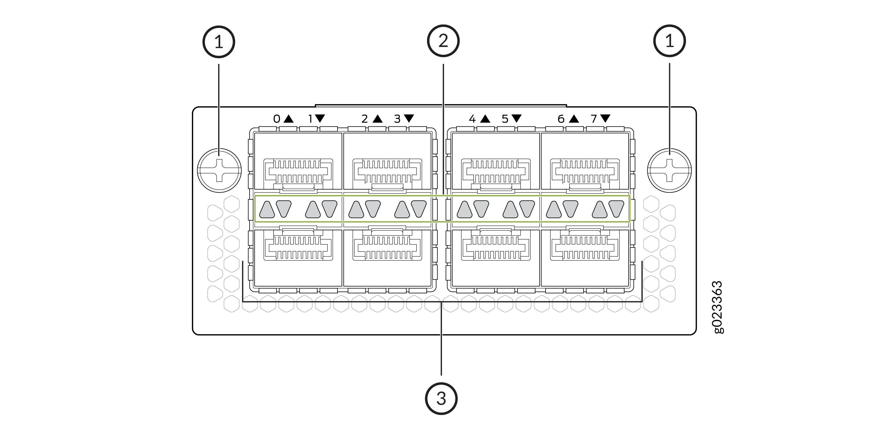
| Callout | Description |
|---|---|
|
1 |
Captive screws |
|
2 |
LEDs |
|
3 |
SFP28 ports |
| Height | Width | Depth | Weight |
|---|---|---|---|
|
36.4 mm |
80.6 mm |
168.4 mm |
0.22 Kg |
2 x 100-GbE (QSFP 28) Uplink/Extension Module
2x100-GbE QSFP28 extension module / uplink module is a pluggable module and
supports 40-Gbps and 100-Gbps transceivers. See Figure 2. The ports in the 2x100-GbE
QSFP28 extension module operate at the default 100-Gbps speed. The two ports can
operate in different speeds independently. You can channelize a port operating
at 40-Gbps into 4 x 10-Gbps and a port operating at 100-Gbps into 4 x 25-Gbps.
To channelize a port, use the set chassis fpc <fpc-slot-no> pic
<pic-slot-no> port <port-no> channel-speed
<speed> command and use a breakout cable.
For example, to channelize port 0, operating at 40-Gbps, into 4 x 10-Gbps, apply
set chassis fpc 0 pic 2 port 0 channel-speed 10 to the
port, and use a 4x10GbE breakout cable. To channelize port 1, operating at
100-Gbps, into 4 x 25-Gbps, apply set chassis fpc 0 pic 2 port 1
channel-speed 25 to the port, and use a 4x15GbE breakout cable.
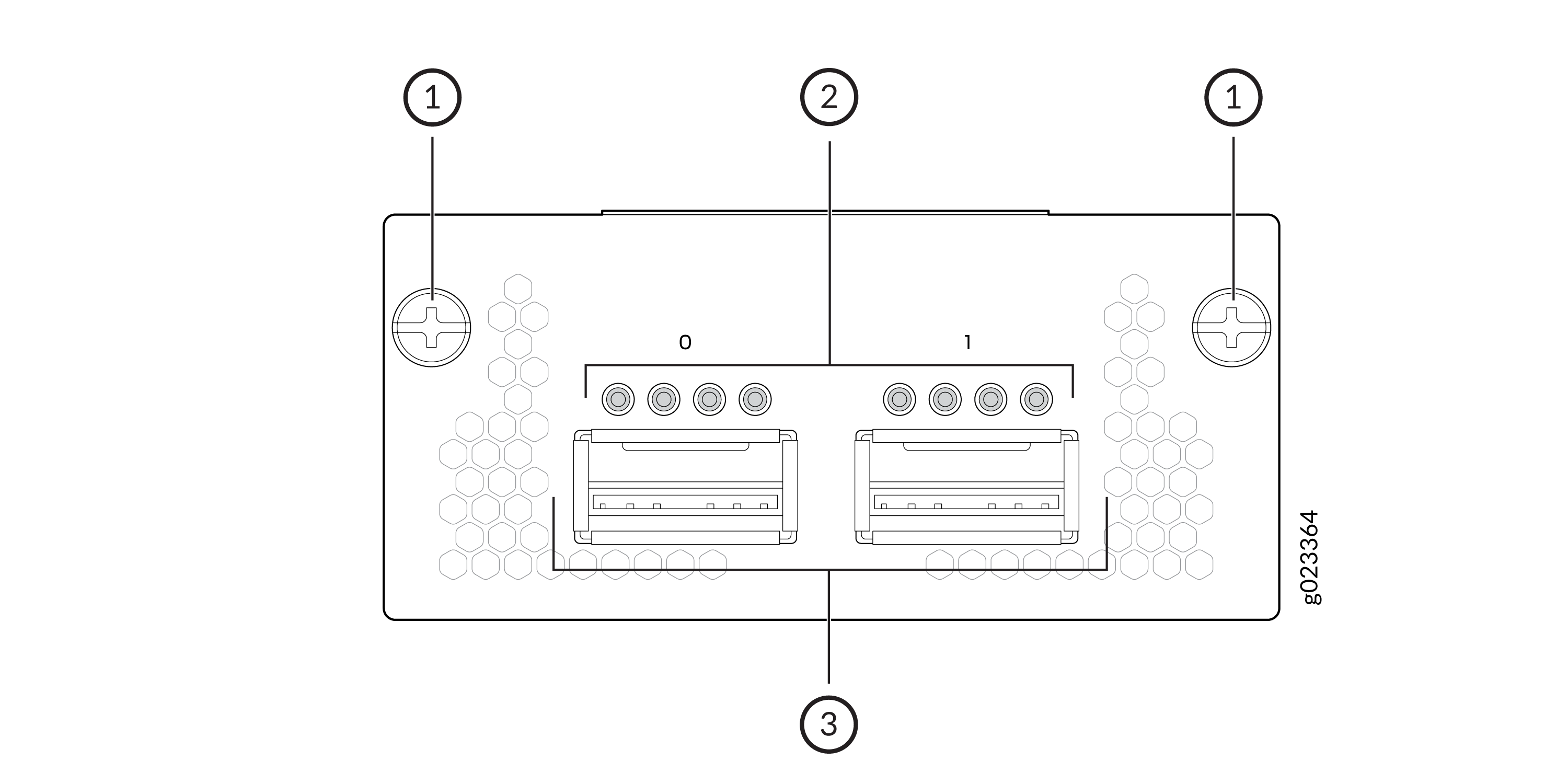
| Callout | Description |
|---|---|
|
1 |
Captive screws |
|
2 |
LEDs |
|
3 |
SFP28 ports |
| Height | Width | Depth | Weight |
|---|---|---|---|
|
36.4 mm |
80.6 mm |
168.4 mm |
0.28 Kg |