EX5200 Cooling System
The EX5200 switch uses fans for cooling.
The cooling system in an EX5200 switch consists of two fan modules for the chassis and a single built-in fan in each power supply. The airflow direction depends on the fan modules and power supplies installed in the switch. The fans and power supplies support Airflow-Out (AFO) airflow direction.
EX5200 switch models are cooled by field-replaceable fans.
-
EX5200-48MP - AFO 3 x Fan FRU
-
EX5200-24MP - AFO 2 x Fan FRU
-
EX5200-48T - AFO 2 x Fan FRU
-
EX5200-24T - AFO 2 x Fan FRU
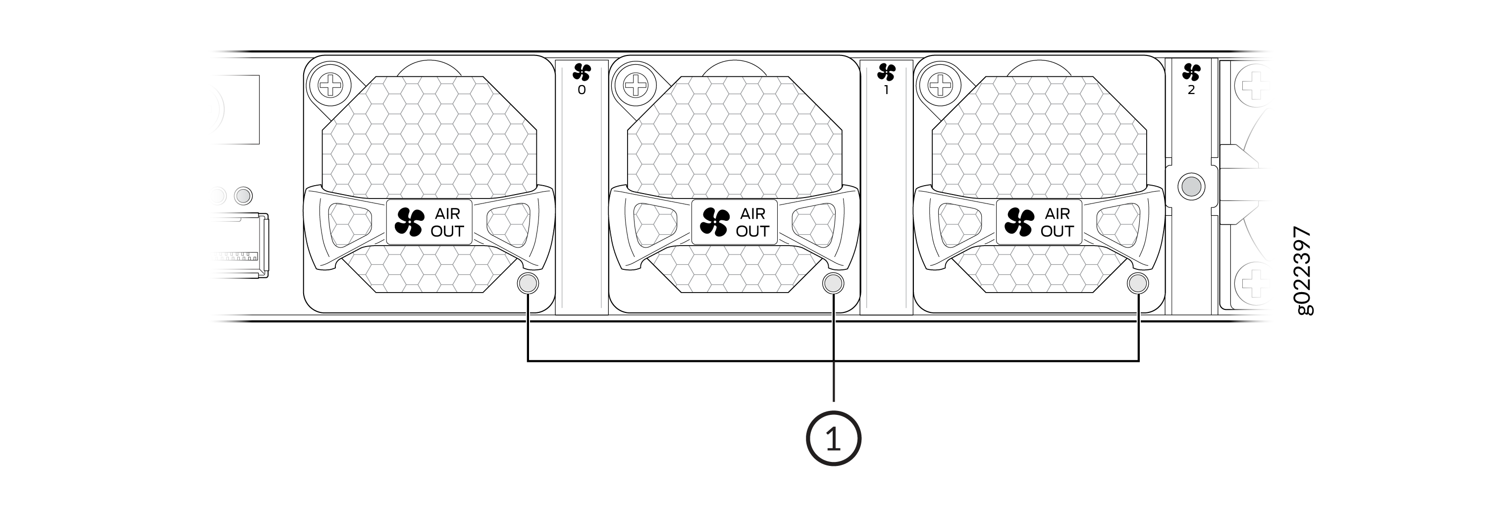
The fan modules are hot-insertable and hot-removable field-replaceable units (FRUs). You can install the fan modules in the fan module slots on the rear of the device.
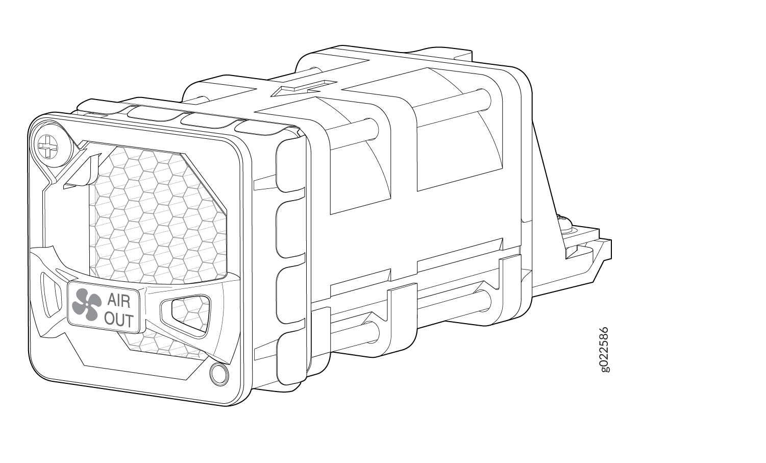
You must install all the fan modules and they must be operational for optimal functioning of the switch.
Leave at least 6 in. (15.2cm) clearance in front and 6 in. (15.2cm) clearance behind the chassis for airflow.
If the switch is operational while you are replacing fan modules, you must remove only one fan module at a time. The switch continues to operate for 60 seconds without thermal shutdown while you are replacing a fan module.
Under normal operating conditions, the fan modules operate at a moderate speed. Temperature sensors in the chassis monitor the temperature within the chassis.
If a fan module fails or if the ambient temperature inside the chassis rises above the acceptable range, Junos OS raises an alarm. If the temperature inside the chassis rises above the threshold temperature, the system shuts down automatically.
Front-to-Back Airflow
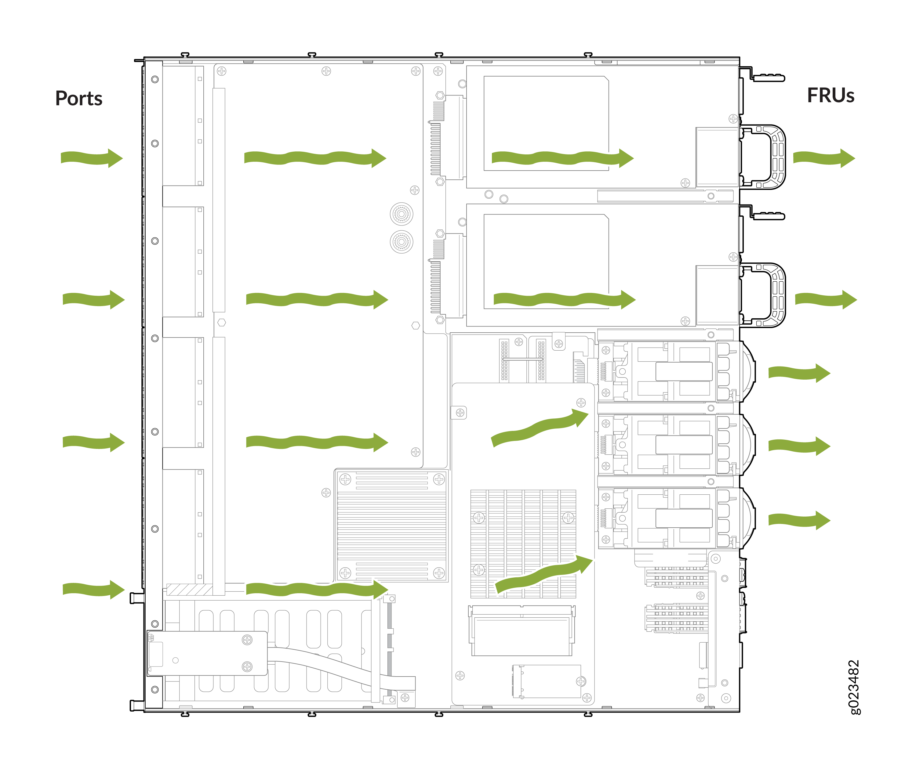
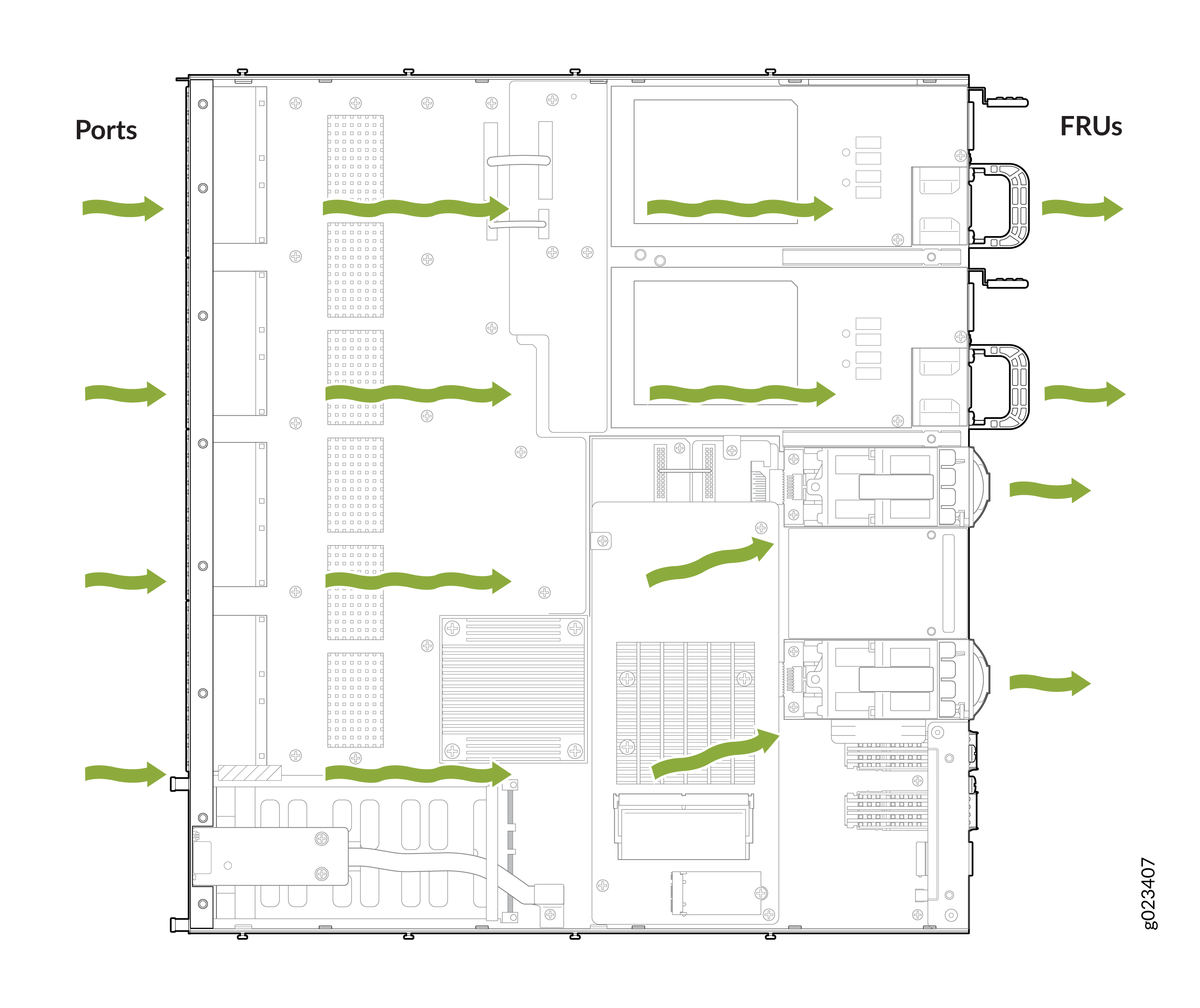
The EX5200 switch has a front-to-back (AIR IN) cooling system. Air is pulled through the front of the chassis toward the fans, which exhaust the air out of the device.
How to Position the Switch
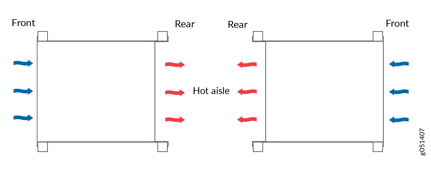
Position the switch with front-to-back airflow in such a manner that the AIR OUT labels on the fan modules and power supplies are next to the hot aisle.
Fan Module Status
Each fan module has a status LED on it that indicates the status of the fan module
|
State |
Description |
|---|---|
|
Lit green |
The fan module is functioning normally. |
|
Blinking amber |
The fan rotor has failed. Replace the fan module. |
|
Unlit |
Indicates one of the following:
|