Connect the EX5200 Switch to the Network
Connecting network cables to the EX5200 switch involves the following steps and safety precautions to prevent equipment damage and personal injury.
The transceivers for Juniper Networks devices are hot-removable and hot-insertable field-replaceable units (FRUs). You can remove and replace the transceivers without powering off the device or disrupting the device functions.
We recommend that you use only optical transceivers and optical connectors purchased from Juniper Networks with your Juniper Networks device.
The Juniper Networks Technical Assistance Center (JTAC) provides complete support for Juniper-supplied optical modules and cables. However, JTAC does not provide support for third-party optical modules and cables that are not qualified or supplied by Juniper Networks. If you face a problem running a Juniper device that uses third-party optical modules or cables, JTAC may help you diagnose host-related issues if the observed issue is not, in the opinion of JTAC, related to the use of the third-party optical modules or cables. Your JTAC engineer will likely request that you check the third-party optical module or cable and, if required, replace it with an equivalent Juniper-qualified component.
Use of third-party optical modules with high-power consumption (for example, coherent ZR or ZR+) can potentially cause thermal damage to or reduce the lifespan of the host equipment. Any damage to the host equipment due to the use of third-party optical modules or cables is the users’ responsibility. Juniper Networks will accept no liability for any damage caused due to such use.
After you insert a transceiver or after you change the media-type configuration, wait for 6 seconds for the interface to display operational commands.
Cable Requirements for Multi-Gigabit Ethernet
For reliable operation at 5 Gbps and 10 Gbps, Cat6A cabling is recommended.
For Cat5e cabling, 100 Mbps, 1 Gbps, and 2.5 Gbps operation is supported as the guaranteed deployment configuration.
Although a link may successfully auto-negotiate to 5 Gbps over Cat5e cabling, 5 Gbps operation over Cat5e is dependent on cable quality, length, installation conditions, and environmental factors. Therefore, successful 5 Gbps link establishment and performance over Cat5e cannot be guaranteed for all deployments.
If deterministic and reliable 5 Gbps operation is required, Cat6A cabling should be used.
Install a Transceiver
Before you install a transceiver in a device, ensure that you have taken the necessary precautions for the safe handling of lasers (see Laser and LED Safety Guidelines and Warnings).
Ensure that you have a rubber safety cap available to cover the transceiver.
Figure 1 shows how to install a QSFP+ transceiver. The installation procedure is same for all types of transceivers except the QSFP28 transceivers.
To prevent electrostatic discharge (ESD) damage to the transceiver, do not touch the connector pins at the end of the transceiver.
To install a transceiver:
-
Slide the transceiver in gently until it is fully seated. If you are installing a C
form-factor pluggable (CFP) transceiver, use your fingers to tighten the captive screws on
the transceiver.
Figure 1: Install a Transceiver

Install a QSFP28 Transceiver
Before you install a transceiver in a device, ensure that you have taken the necessary precautions for safe handling of lasers (see Laser and LED Safety Guidelines and Warnings).
Ensure that you have a rubber safety cap available to cover the transceiver.
To prevent electrostatic discharge (ESD) damage to the transceiver, do not touch the connector pins at the end of the transceiver.
To install a QSFP28 transceiver:
-
Position the transceiver in front of the port on the device so that the QSFP28
connector faces the port.
Figure 2: Install a QSFP28 Transceiver

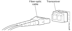
Connect a Fiber-Optic Cable
Before you connect a fiber-optic cable to an optical transceiver installed in a device, ensure that you have taken the necessary precautions for the safe handling of lasers (see Laser and LED Safety Guidelines and Warnings).
Do not look directly into a fiber-optic transceiver or into the ends of fiber-optic cables. Fiber-optic transceivers and fiber-optic cables connected to transceivers emit laser light that can damage your eyes.
To connect a fiber-optic cable to an optical transceiver installed in a device:
-
Insert the cable connector into the optical transceiver.
Figure 3: Connect a Fiber-Optic Cable to an Optical Transceiver Installed in a Device