キャンパス ファブリック EVPN マルチホーミングの設定(EX および QFXシリーズスイッチ)
EVPNマルチホーミングを設定して、コア層とディストリビューション層を1台のスイッチに統合するには、以下の手順に従います。
ジュニパーネットワークス のキャンパスファブリックEVPN マルチホーミングソリューションは、コラプストコアアーキテクチャをサポートします。このアーキテクチャは、コア層とディストリビューション層を1台のスイッチに統合します。これらの層を1台のスイッチに統合すると、従来の3層の階層型ネットワークが2層のネットワークに変わります。また、このアーキテクチャでは、アクセスレイヤーからコアレイヤーまでのマルチホーミング機能を提供することで、キャンパスネットワーク全体でSTPが不要になります。
-
トポロジータイプEVPNマルチホーミングは、サイト固有のキャンパスファブリックでのみ使用できます。組織レベルで構築することはできません。
-
2025年5月の更新以降にMist クラウドに構築されたトポロジーでは、MistがEVPNループと重複するMACアドレスを自動的に検出して報告します。これらの問題は、スイッチのインサイトページに表示されます。
-
EVPNループ検知—EVPN-VXLAN軽量PE-CEループ検知は、ダウンストリームのリーフツーサーバーまたはアクセスポート上のLANイーサネットループの検知と遮断に役立ちます。この機能は、ファブリックコンポーネントの配線ミスやサードパーティ製スイッチのファブリックへの誤接続などの問題によって引き起こされるループを検出できます。この機能を使用するには、スイッチで Junos OS バージョン 24.4R1 以降が実行されている必要があります。詳細については、「 EVPN-VXLAN Lightweight Leaf to Server Loop Detection」を参照してください。
-
重複MACアドレス検知—EVPN環境内の異なるインターフェイスまたはデバイス間のMACモビリティMACアドレスの移動から生じる問題を特定して軽減します。ある程度のMACモビリティは想定されますが(たとえば、デバイスが実際に動いたとき)、急激な変化はネットワークループや設定ミスなどの問題を示している可能性があります。詳細については、重複MAC アドレスのループ検出の設定を参照してください。
-
重複するVLAN ID —EVPNオーバーレイとアンダーレイ(APトランクポートなど)で重複するVLAN IDによって引き起こされる非コアスイッチのファブリック内のループを検出します。このオーバーラップにより、レイヤー2の並列転送パスが作成され、特にAPトラフィックがMist Edgeにトンネリングされる場合、ブリッジングループ、ブロードキャストストーム、サービスの低下が発生する可能性があります。イベントは、インサイトページにファブリックループが検出されたと表示されます。
-
詳細な設定例については、 キャンパスファブリックEVPNマルチホーミングワークフローを参照してください。
キャンパスファブリック構成のベストプラクティス
- スイッチテンプレートレベルでVLANを設定し、キャンパスファブリックの設定中にインポートします。テンプレートは、スイッチまたはサイトレベルで特に必要とされない限り、すべてのVLANとポートプロファイルの信頼できる唯一の情報源である必要があります。
- アクセス層では、明示的に必要な場合を除き、すべてのVLANを許可するトランクポートプロファイルを使用しないでください。
- スイッチテンプレートではなく、キャンパスファブリックを介してVRFおよびVRFネットワーク設定を作成します。
- ロールごとにポート割り当てを作成し、必要に応じて個々のデバイスの設定を上書きします。
- サービスブロックデバイスを除く、キャンパスファブリックのワークフローを介してDHCPリレー設定を管理します。
キャンパスファブリックEVPNマルチホーミングを設定するには:
- 左側のナビゲーションメニューから、組織>キャンパスファブリックを選択します。
- ページ見出しの横にあるサイトドロップダウンリストから、キャンパスファブリックを構築するサイトを選択します。
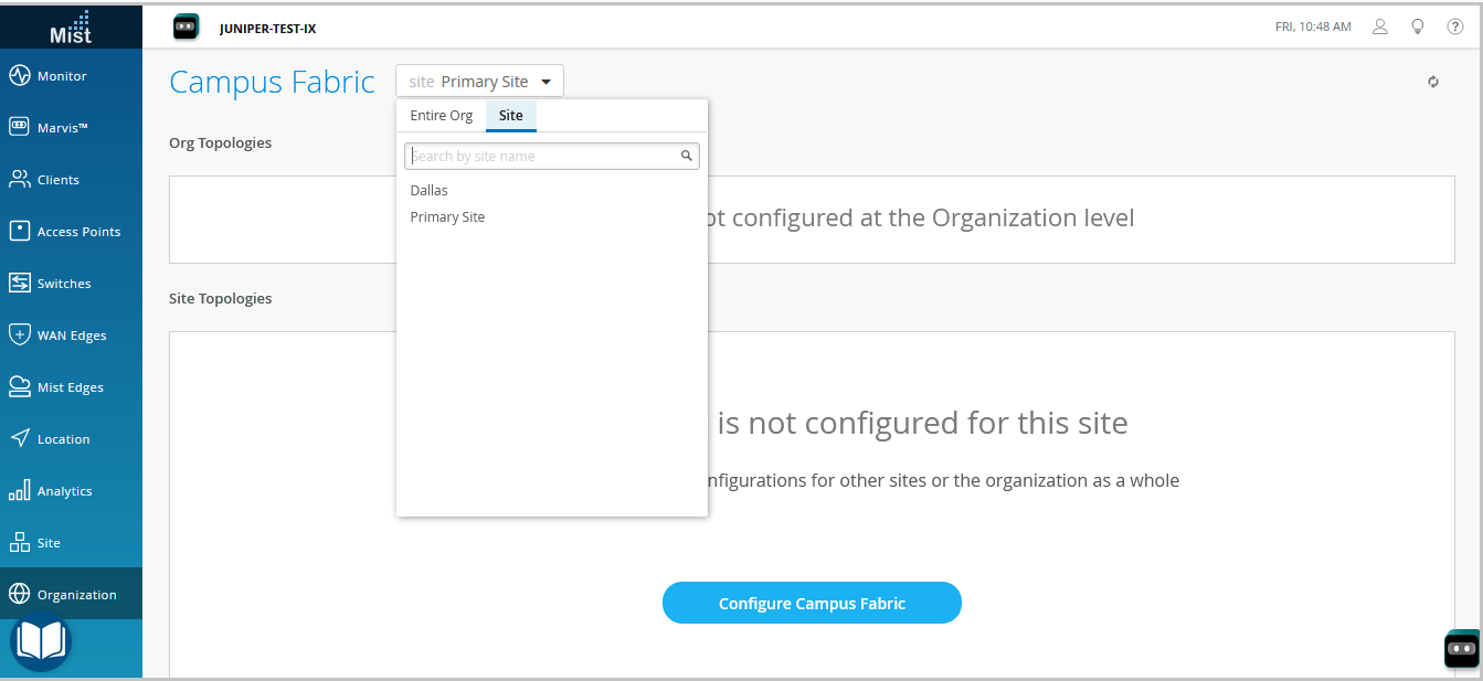
- 関連するオプションをクリックします。クリック:
-
キャンパスファブリックの設定ボタン(サイトにキャンパスファブリック設定が関連付けられていない場合に表示されます)。
-
キャンパスファブリックの作成ボタン(サイトに少なくとも1つのキャンパスファブリック設定が関連付けられている場合に表示されます)。
トポロジータブが表示されます。 -
- トポロジータイプ EVPNマルチホーミングを選択します。

- トポロジータブで残りの設定を、以下で説明するように構成します。
注:
キャンパスファブリックに接続されているネットワークと競合しない限り、この画面のデフォルト設定を使用することをお勧めします。各レイヤー間のポイントツーポイントリンクは、アドレスを節約するために/31アドレッシングを利用します。
- CONFIGURATIONセクションで、以下を設定します。
-
トポロジー名—トポロジーの名前を入力します。
-
仮想ゲートウェイv4 MACアドレス—このオプションを有効にすると、WLAN上のゲストポータルのリダイレクトがサポートされます。の場合、Mistは各レイヤー3(L3)仮想ゲートウェイに(ネットワークごと)に一意のMACアドレスを提供します。デフォルトでは無効になっています。
-
- (デフォルト設定を使用しない場合)オーバーレイ設定セクションに以下を入力します。
-
BGPローカルAS—Mistが各デバイスに自動的に割り当てるプライベートBGP AS番号の開始点を表します。導入に合った任意のプライベートBGP AS番号範囲を使用できます。Mistは、ファブリックのアンダーレイでループバックIPアドレスのみが交換されるように、ルーティングポリシーをプロビジョニングします。
-
- (デフォルト設定を使用しない場合) アン ダーレイ設定 セクションで、以下を設定します。
-
ASベース—ASベース番号。デフォルトは65001です。
-
アンダーレイ—アンダーレイのインターネットプロトコルバージョンを選択します。オプションはIPv4とIPv6です。
-
サブネット—Mistがデバイス間のポイントツーポイントリンクに使用するIPアドレスの範囲。導入に合わせて範囲を使用できます。Mistは、このサブネットをリンクごとに/31サブネットアドレスに分割します。この数は、特定の導入規模に合わせて変更できます。たとえば、/24 ネットワークは最大 128 のポイントツーポイント /31 サブネットを提供します。
-
IPv6ループバックインターフェイス—ファブリック内の各デバイスでIPv6ループバックインターフェイスを自動設定するために使用されるIPv6ループバックインターフェイスサブネットを指定します。
-
自動ルーターID サブネット/ループバックインターフェイス—Mistは、このサブネットを使用して、ファブリック内の各デバイス(EVPNが設定されているかどうかに関係なく、アクセスデバイスを含む)にルーターIDを自動的に割り当てます。ルーターIDは、デバイス間のオーバーレイピアリングに使用されるループバックインターフェイス(lo0.0)です。新しいトポロジーの場合、このフィールドにはデフォルトのサブネット値(172.16.254.0/23)が自動入力されます。これは変更できます。既存のトポロジーを編集する場合、このフィールドにはデフォルト値は入力されません。ルーターIDは、BGPなどのルーティングプロトコルを展開する際の識別子として使用されます。スイッチをコラプストコアレイヤーに追加した後、スイッチアイコンをクリックして、関連するルーターIDを確認します。
IPv4導入では、自動ルーターID割り当てを無効にし、ルーターIDを手動で設定するオプションがあります。そのためには、このフィールドを空白のままにしてから、ノードタブからルーターIDを手動で設定 します 。
IPv4導入の場合、スイッチ設定ページ(スイッチ名>スイッチ)のルーティングタイルにあるルーターIDフィールドでループバックインターフェイスを手動設定することで、自動的に割り当てられたルーター IDを上書きすることもできます。ただし、その後キャンパスファブリックの設定を変更すると、MistはルーターIDの自動割り当てを再度実行し、手動で設定したループバックインターフェイスと置き換えます。
-
- CONFIGURATIONセクションで、以下を設定します。
- 続行をクリックしてノードタブに移動します。ここでは、キャンパスファブリックの導入の一部を構成するデバイスを選択できます。

- コラプストコア層とアクセス層にスイッチを追加します。
キャンパスファブリックを作成する前に、スイッチのインベントリに各デバイスの存在を検証することをお勧めします。
スイッチを追加するには:
- スイッチの選択をクリックします。
- キャンパスファブリックに追加するスイッチを選択します。
- 選択をクリックします。
注:トポロジータブの自動ルーターIDサブネット/ループバックインターフェイスフィールドを空白のままにした場合、スイッチのルーターIDを手動で設定する必要があります。そのためには、ファブリックに追加したスイッチを選択し、右側に表示されるペインでルーターIDを設定します。手動ルーターIDの割り当ては、IPv4導入でのみサポートされています。
- スイッチを選択したら、[ 続行] をクリックして[ ネットワーク設定 ]タブに移動し、そこでネットワークを設定できます。
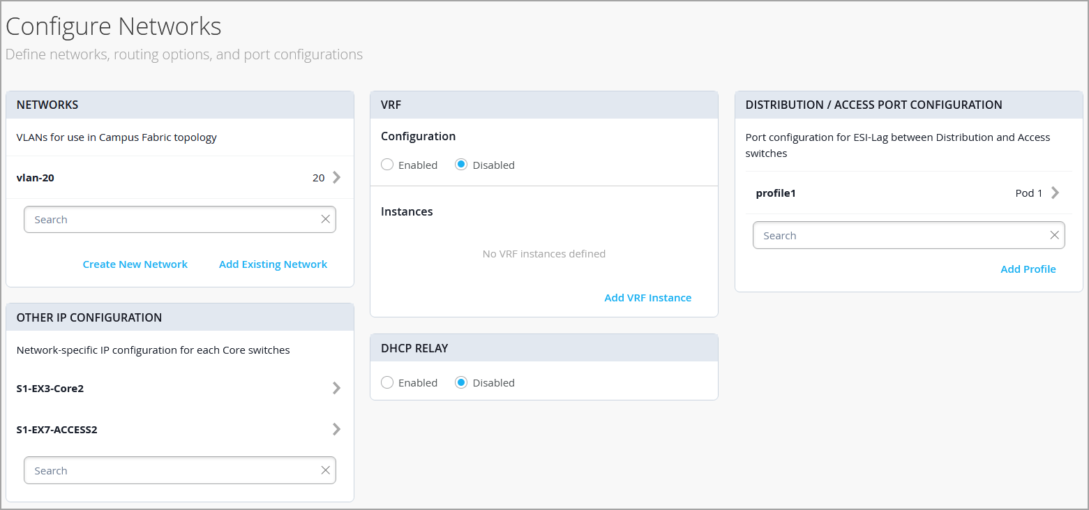
- 以下の説明に従ってネットワーク設定を構成します。
- ネットワークタイルで、ネットワークまたはVLANを設定に追加します。新しいネットワークを作成するか、組織>スイッチテンプレートページで定義されたスイッチテンプレートからネットワークをインポートできます。
新しいVLANを追加するには、 新しいネットワークを作成 をクリックし、VLANを設定します。設定には、名前、VLAN ID、サブネットが含まれます。サブネットにIPv4またはIPv6アドレスを指定できます。
テンプレートからVLANをインポートするには:
-
既存のネットワークを追加をクリックします。
-
テンプレートドロップダウンリストからスイッチテンプレートを選択すると、そのテンプレートで使用可能なVLANが表示されます。
-
表示されたリストから必要なVLANを選択し、✓マークをクリックします。
VLAN は仮想ネットワーク識別子(VNI)にマッピングされます。オプションでVLANを仮想ルーティングおよび転送(VRF)インスタンスにマッピングして、トラフィックを論理的に分離できます。
-
- [ その他の IP 設定] タイルの設定を確認します。このセクションでは、「ネットワーク」セクションでネットワークを指定すると、設定が自動的に入力されます。
- オプションで、VRFインスタンスを設定します。セグメントベースのキャンパスファブリックアーキテクチャでタイプ5(IPプレフィックス)ポリシーを適用する場合は、VRFの使用を推奨します。デフォルトでは、MistはすべてのVLANをデフォルトのVRFに配置します。VRF オプションを使用すると、トラフィック分離の要件に応じて、共通の VLAN を同じ VRF または個別の VRF にグループ化できます。各VRF内のすべてのVLANは、相互および他の外部ネットワークリソースと完全な接続を持っています。一般的な使用例は、インターネット接続を除くほとんどのエンタープライズドメインからゲストの無線トラフィックを分離することです。デフォルトでは、キャンパスファブリックはVRF間を完全に分離し、VRF間の通信がファイアウォールを通過することになります。VRF 間通信が必要な場合は、VRF への追加ルートを含める必要があります。追加ルートは、外部ルーターを使用するようにキャンパスファブリックに指示するデフォルトルートにすることができます。また、セキュリティ検査やルーティング機能を強化するためのファイアウォールになることもあります。
VRFを作成するには:
-
VRFタイルで、 VRFインスタンスを追加 をクリックし、設定を指定します。設定には、VRF の名前と、VRF に関連付けるネットワークが含まれます。
-
ルートを追加するには、新しいVRFインスタンスページにあるルートを追加リンクをクリックし、ルートを指定します。IPv4またはIPv6アドレスを指定できます。
-
- [CORE / ACCESS PORT CONFIGURATION] タイルで、コラプストコアとアクセス スイッチ間の ESI-LAG のポート構成を完了します。設定には、名前やその他のポート構成要素が含まれます。デフォルトでは、この設定には、同じページのネットワークタイルに追加されたネットワークが含まれます。設定を削除または変更する場合は、[詳細を表示]をクリックして設定を構成します。画面のヒントを使用して、ポートプロファイル設定を構成します。
- DHCP RELAYタイルで、DHCPリレー設定を構成します。以下のオプションがあります。
-
有効—キャンパスファブリック内のすべてのIRB対応デバイスでDHCPリレーを設定します。このオプションを使用すると、選択したネットワークでDHCPリレーを有効にできます。ネットワークは、同じページのネットワークタブに表示されている限り、DHCPリレータイル内に入力されます。
-
無効—キャンパスファブリック内のデバイスのDHCPリレーを無効にします。このオプションを選択すると、すべての IRB 対応デバイスで DHCP リレーが無効になります。このオプションは慎重に選択する必要があります。スイッチの詳細ページでローカルで定義されたDHCPリレーが削除されます。
-
なし—このオプションは、キャンパスファブリックトポロジーにDHCPリレー設定に関してデバイスが混在している場合に自動的に選択されます。つまり、DHCP リレーが有効になっているデバイスもあれば、無効になっているデバイスもあれば、定義されていないデバイスもあります。このオプションは、個々のスイッチでローカルにDHCPリレーが定義されているすべてのキャンパスファブリックトポロジーに表示されます。
ローカルで定義されたすべてのDHCPリレーネットワークを削除する場合は、[ 有効] を選択し、[ 既存のデバイスレベルのDHCPネットワークをすべて削除する]を選択します。キャンパスファブリックのワークフローからの設定変更を一元化することで、DHCPリレーの導入を簡素化できます。
キャンパスファブリック設定でDHCPリレーを有効にすると、ファブリック内のすべてのIRB定義デバイスで有効になり、残りのデバイスで無効になります。例えば、EVPNマルチホーミングトポロジーでは、コラプストコアデバイスではDHCPリレーが有効になり、残りのデバイスでは無効になります。
-
- ネットワークタイルで、ネットワークまたはVLANを設定に追加します。新しいネットワークを作成するか、組織>スイッチテンプレートページで定義されたスイッチテンプレートからネットワークをインポートできます。
- 続 行 をクリックして ポート タブに移動します。このタブではポートを設定し、コア、ディストリビューション、アクセスレイヤースイッチ間の接続を作成できます。
- コラプストコア層のスイッチポートを次のように設定します。
- [Collapsed Core]セクションでスイッチを選択して、スイッチポートパネルを開きます。
- スイッチのポートパネルから、設定するポートを選択します。
- ポートタイプを指定します(例:
ge、xe)。 - 選択:
-
ポートをコアスイッチに接続するには、Collapsed Coreにリンクします。
コラプストコア層では、各スイッチを他のスイッチに接続して、フルメッシュトポロジーを形成できます。フルメッシュトポロジーにより、EVPNマルチホーミングキャンパスファブリックの耐障害性が向上し、1台のデバイスに障害が発生した場合でもネットワーク機能を継続できます。
-
リンクして、 ポートをアクセス スイッチに接続します。
-
- リンクを終端するコアまたはアクセススイッチを選択します(前のステップでの選択に基づいて)。キャンパスファブリックの一部となる必要があるすべてのポートを設定する必要があります。
 アクセスレイヤーでスイッチポートを設定するには:
- アクセスセクションでスイッチを選択し、スイッチポートパネルを開きます。
- スイッチのポートパネルから、設定するポートを選択します。
- ポートタイプ(
geやxeなど)を指定します。アクセスレイヤーでバーチャルシャーシ(VC)を使用する場合は、[プライマリ]タブと[バックアップ]タブでポートを設定できます。
アクセススイッチでは、分散型スイッチとの相互接続に使用するインターフェイスのみを選択します。システムは、AEインデックスオプションを使用して、すべてのインターフェイスを単一のイーサネットバンドルにバンドルします。アクセス デバイスのAEインデックス値を指定できます。
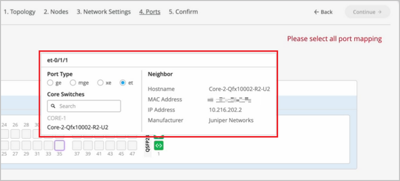
特定のポートの設定とステータス情報を表示したい場合は、ポートパネルUIでそのポートを表す番号付きボックスにカーソルを合わせます。
- 続 行をクリックして 、 確認 タブに移動します。
- 各スイッチアイコンをクリックして、設定を表示および検証します。
- 設定を確認したら、 変更を適用 > 確認をクリックします。
この手順では、キャンパスファブリックの設定をMistクラウドに保存し、スイッチに適用します。スイッチがオフラインの場合、次回オンラインになったときに設定が適用されます。スイッチの設定が完了するまでに最大 10 分かかることがあります。
- キャンパスファブリック設定を閉じるをクリックします。
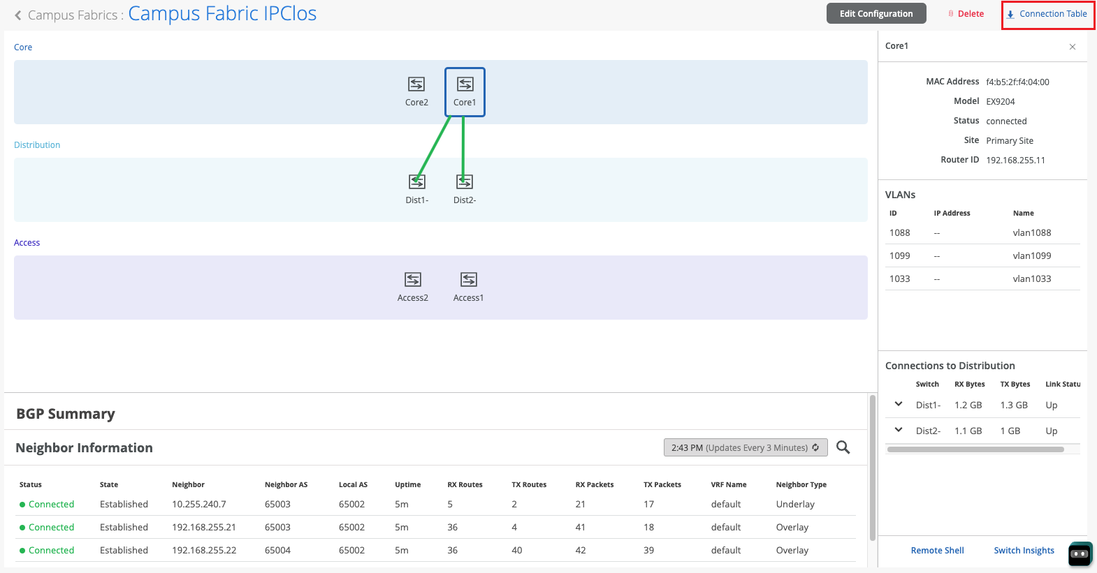
Mistがキャンパスファブリックを構築した後、またはファブリックを構築している間に接続テーブルをダウンロードできます。接続テーブルは、キャンパスファブリックの物理的なレイアウトを表しています。このテーブルを使用して、物理キャンパスファブリックの構築に参加しているデバイスのすべてのスイッチ相互接続を検証できます。接続 テーブル をクリックしてダウンロードします(.csv形式)。
- キャンパスファブリック構成を検証します。確認するには、キャンパスファブリックEVPNマルチホーミングワークフローの検証セクションに記載されている手順に従います。
Hello and welcome to this edition of Wired Assurance. My name is Rohan Chada and today I'll be talking about building an EVPN week stand campus fabric in just four steps. Today we're going to talk about the deployment of EVPN multi homing topology. I'll walk you through the different steps that are required and I can promise you none of those require any CLI configuration.
Everything will be done through the UI and it'll be as simple as you can expect it to be. So let's just jump right into it and talk about EV Pin Multi Hamming. Before we jump into building the EV Pin Multi Hamming topology, let's understand the building blocks of it from a device perspective. Today as you can see, we're going to be using 2 core devices and two access devices.
The EVPN Multi Hamming topology can support up to 4 core devices, a minimum of two and a maximum of four and as many access devices as you'd like. But for this purposes of this video, we'll be using 2 core devices and two access devices. So to begin with, we click on organization and we under the wire tab we see Campus fabric. So as we click on Campus fabric, we can see that we are inside the site EVPN campus primary one and there is no campus fabric configured at this time.
And that's exactly where we'll begin. Click on configure campus fabric and we see that there are three topologies that are presented to us. EVPN multi homing which is collapse code with ESI lag, campus fabric Code distribution which is EVPN code distribution with ESI lag and canvas fabric IP cloth. What you see on the left side of each of these three names is a small diagram that basically depicts the topology that this this entails.
So you basically have above the line that you see the horizontal line in the diagram on each of these topologies. Above the line is where your your evpn vxlan construct exists. And what I mean by that is that's where those devices are, the devices that run Evpn vxlan configuration. Anything below the horizontal line are just pure access devices layer to they can be, they have to be non evpn VXLAN capable devices.
So once you've selected the EVPN multi homing we see that it's a collapsed core and what that means is that two or three layers of EVPN configuration is collapsed into just one layer. So we'll jump right in there by giving it a topology name. We're going to go ahead and call it evpn image. There are two settings that you have to provide on the initial page and that's for the overlay and the underlay settings.
For overlay we use ibgp today and for underlay we use ebgp. The default values will be presented to you, there is no reason to change it if there isn't a purpose behind it. And 65,000 is the local AS and 65,001 is the AS base to begin with for the underlay ebgp. And then we'll increment sequentially on a device spaces starting with 65001.
The loopback prefix as you can see is the the prefix that's used to assign to all the interfaces, all the loopback interfaces on all the devices. These interfaces are used to peer with every other VTAP in the campus fabric. And then last is the subnet, which is again a default value provided that can be changed by the user. This subnet is used to connect the underlying physical interfaces between the campus fabric.
Let's jump right into the next step and click on Continue. At this step we'll be selecting the Campus fabric nodes. In this Campus fabric configuration we'll be selecting 2 Campus course and I'll select Code one and Code 3 for this demo. And as you can see in this nice drop down, you have all the information provided to you and that includes the model as well as the Mac address so you don't have to go back and forth between different pages of the UI.
Every information is provided right here. For the access devices, I'll be picking switch one and switch two. My core devices are EX 465048 wise that are EVPN capable. My access devices are EX 2300 and 4300 that do not understand EVPN.
Hence I am putting these in an access layer. The platform support on a topology basis is on the on the website and we've listed every platform that's supported on a per layer basis. So once you've selected this topology, we know that there are two core devices, 2 access devices. I can click on these core devices and I can see that the basic information about core one I see there is a router ID assigned.
This router ID is assigned as needed for the loop back interface. As I mentioned earlier, that's used for peering between the two core devices. In case of a collapsed core, the two core devices will act as the as the two vtips that basically they will be forming A VXLAN tunnel between each other. The access, which is on the other hand do not necessarily need a router ID, but we've provided them for consistency's sake.
They do not need it, but let's go ahead with that. Step three is basically configuring networks. So networks are basically of Vlans. So we'll go ahead and start creating some new networks here.
I'm going to be assigning some generic names here and I'll call it image vlan 10 and S and vlan ID 10 and I'll give it the subnet 190 to one 6810.0 slash 24 and I'll give it a virtual gateway for 190 to 168 dot 10.1. Now providing this subnet is. This is the only I would say.
This is the second step wherein you'll be providing us a subnet. The IP addressing for the IRB slash SVI interfaces or any IP addressing in the underlying physical interfaces in our fabric is taken care by missed Wire Assurance Campus Fabric. As a user and administrator, you don't have to worry about it. So once you've provided us a subnet, we'll take care of it.
So this virtual gateway will essentially be used for as a common address between the two core devices. So any underlying device, for example an access switch or any any device connected to the access switch will have its gateway as 190 to 168 or 10.1 which will be advertised via avpn and that's why we come in here and manually define it. So as you can see, I created a VLAN, VLAN 10 and voila, we see two IP addresses that have already been chosen to be assigned for the corresponding IRB slash SVI interfaces that will be assigned to code one and code 3 for VLAN 10.
Let's go ahead and create another one and we'll call it image VLAN 20. But in this case I'm not going to assign a subnet or virtual git net because I want to route for this particular VLAN. I want to route on the the the firewall of the campus fabric. So my the two core devices that I have will be connected dual home to a firewall and I want the routing to happen for this particular VLAN on the firewall.
So I'm going to skip this and this is basically a bridged overlay design wherein we'll assign the VNI to the corresponding VLAN 20, but we will not be configuring A subnet or a gateway on the 2 core devices. This is one way of creating a VLAN. The other way of adding a VLAN to the campus fabric is if you have existing network on the sites already. So we'll click on existing network and what we see is that there is a common VLAN that we already created earlier before we started this demo on an entire site.
So using the site configuration here, I created a VLAN called site wide VLAN with a VLAN ID of 100 and that's it. And what that did was all the devices in that site inherited the site wide VLAN. So I'm going to take site wide VLAN and I'm going to add that. So now I'm told that there is a virtual gateway that is required.
OK, there is a virtual gateway required. So we'll go ahead and add the virtual gateway. The subnet basically was inherited from the the site configuration where I had created VLAN printer. So I'm being told that the provided gateway is already used.
OK, so here we have 3 Vlans and as we already see that for two of them the static IP addresses have already been defined. For VLAN 10 there are two IP addresses, code one and code 3. Similarly for site VLAN 100, we have two IP addresses, one each for core one and core 3. And as we already know VLAN 20 is a doesn't have a virtual gateway on the collapse core, so we do not have a gateway for that.
Now let's jump into VRF and understand this is virtual routing and forwarding wherein you can create separate routing instances. You can basically increase the security in your network by segregating the Vlans in different routing instances. A different routing instance basically means that there is a different routing table on a per VLAN basis or however many Vlans you would like in that particular VRF. So we'll go and assign this name vrf one and then we'll we'll add image vlan 10 to vrf one if if there is a need.
I can always add extra routes within the VRF as well and that is an option. You go ahead and another VRF called VRF 2 and I'll use site by vlan for this particular VRF 2. The last step on this page is to basically configure the core access port configuration. This is the port configuration towards the access switches from the collapse code as it if you read the description it says this is the ESL configuration.
So let's just assign it a name and let's call it Yesi LAG, any name of the book, but Yesi Haffen LAG is what I've assigned. We presume that all the Vlans and networks that you've defined here are going to be a part of the ESI LAG configuration, and so we automatically add them to the trunk networks. You can come in here and manually change any settings that you would like. If you would like a smaller MTU or if you would like to manipulate the MTU size here to your environment needs, you can do that.
You can enable storm control. You can also enable Poe if that's a requirement, change the speed, duplex, add native VLAN. All of that is an option that we've provided. This is the last and final step and what we see here is there are different port panels.
These port panels are on a platform basis. For the purposes of this video, we are using EX4650 and two other platforms. So we'll show you the appropriate port panels as needed whenever any platform other than these are used. So let's jump right into it and let's let I'll go ahead and I'll configure these interfaces quickly.
So what I've done at this point is I've connected all the two collapsed core devices with the other two access devices. Basically the requirement is that there should be two interfaces connected to each other between the two core devices. Evpn multi Homing has that requirement for redundancy and then core one needs to connect to both access switch one and Access switch 2. Similarly code 3 needs to connect to both access switch one and access Switch 2.
So once those interfaces have been have been connected here you've told the missed UI that these are the interfaces. We can proceed and we can click on continue. This is the last step wherein you confirm that the topology changes that you want are there and if you click on code 1, we can see that on the right. We see a lot of information about everything that we've done so far.
We see the model, we see the router ID, we see the Vlans that we wanted in the campus fabric. Along with the Vlans we also see the IP addresses. I see that there are two IP addresses and three Vlans. One of them is and doesn't have an IP address and that is basically a bridge overlay design as I mentioned earlier.
We also see the connections by the way. I can see and I can verify here the connections connections to collapsed core or three and access switch one and access switch two at any point in this entire step. If you'd like to access the remote shell, we've provided you that option as well. So before you hit apply changes, if you'd like to log into your device you can do that here.
You can click on remote shell and pop up window will open for you and at this point you can you can look at your configuration. You can look at how your devices are connected. I see here that my devices are connected or one connects to two core 3 interfaces and core one has a connection to switch to and switch one as well. So a a little handy tool here where you can verify by logging into the device.
Let's click apply changes and confirm. At this time, what has happened is that the configuration that we decided to push to the devices is being pushed and is being committed to the junuper devices and right after that's committed, BGP Underlay as well as Overlay will be provisioned. Once BGP Underlay is provisioned, overlay and the VX LAN tunnels will come up, the VX LAN tunnel will be two way between collapsed Core one and collapsed Core 2. Let's just jump right into the switches while this configuration is happening.
We look at what's the scenario and the switches and the configuration that we pushed under the hood. Remember, everything that we did so far was based on UI. We did not touch the CLI. We did not make any CLI changes manually.
You did not have to define the EVPN configuration or the BGP configuration or the underlying physical connectivity. This is the value of Missed Wire Assurance Campus Fabric. Let's click on Utilities and click on Download JS Config. We see that configuration file has been downloaded.
This is a. This is a handy tool. What this does is it enables us to verify the configuration. All of us have been used to configuring things while the CLI and so it is very important that we verify that if you're doing this for the first time that everything that you want in the configuration should be there.
You could be a Greenfield environment or or a brownfield environment. You should be able to verify your configuration. So let's dive right into it. Let's look at this.
So as we can see, the first thing I see is I see some BGP configuration here. That's very important. We see the underlay BGP configuration here between the two core devices. There are two peers here on 2 interfaces.
We see the overlay configuration here since there's only one peer for core one and that is core three. There is only one neighbor. We see some EVPN configuration here, right? We also see the ESI LAG configuration here that was pushed by Campus Fabric.
None of that required us to push anything through CLI. We see 22 LAG interfaces AE0 and AE1AE0. It's towards switch one and AE three is towards switch two. We see the IRB configuration as we discussed earlier.
IRB 10 is the the first VLAN that we defined with a gateway and IRB 100 is the third one that was inherited from the site wide template. We also see the VRF configuration here. So as we can see, there's VRF one configuration that has one VLAN IRB .10. We also have type 5 routes as a part of it.
We also see VRF 2 configuration in this VRF 2 configuration, what we see is IRP 100. The second, I'm sorry, the third VLAN that we chose is also there. And then if you look at the configuration here, we see all three Vlans, even the VLAN, even the VLAN that we made bridged overlay is a part of the configuration has a VNI. So we can go ahead and we can assign the gateway for this particular VLAN on either the router of the campus fabric or the firewall based on your environment.
So now that we've looked at the configuration, let's look at how our EVPN campus fabric is doing and what do the EVPN insights tell us. So the EVPN insights, it's basically a pretty layer on top of the campus fabric that tells you about a few green and red links. And those green and red links are not not just the the interface status. They tell you some good information about your peering in the network.
So we looked at there are a few green links. We see that the status is up, but we see these triangles. And these triangles are not, they do not look great. So when I hover over this topology, I am being told that the selected port is not connected to the correct switchboard in the campus traffic topology.
What that basically means is that the the the back end of the campus fabric knows that the core one to core 3 port that I've selected is not the right port and instead it is something else. It is smart enough to understand that there was another port that should have been connected, but I have connected the wrong the wrong port and that is absolutely right. So I'm going to jump right into the campus fabric and change that quickly for you guys. So I'll click on edit configuration and go right to the last step and I'll change this zero to 1 and we'll hit continue and we'll apply changes and save them while the provisioning takes a while.
I'll be right back in a minute. So, so we're back. So as we can see our pretty green lines are back. What and what that means is that we've you corrected the interface that was not correct in the right way.
Campus Fabric was smart enough to let us know that the interfaces that were connected between code one and code three were not right. As you can see, I had 000 earlier and I switched that over to 001 and after doing that my BGP neighborship came back. And then here we can see if I click on any device the statistics between the two devices. We can also see, as I mentioned earlier, the Vlans and the IP addresses.
Thank you. This concludes our campus fabric demo today. I'll summarize all the things that we did today in this last 2025 minute session. So we built a campus fabric using the Mist UI.
None of those steps included anything to do on the CLI. We built a campus fabric in four steps wherein we as a step one, we selected the kind of topology that the user would want. As a second step, we chose the campus fabric nodes that will participate in the campus fabric. The third step was to provide us the networks that will be participating in the in the campus fabric.
And the last and final step was the connectivity of the devices itself. It's as simple as that.