このページの内容
MPLSのトラブルシューティング
MPLSインターフェイスの検証
目的
ネットワーク内のルーターに MPLS プロトコルが正しく設定されていない場合、インターフェイスは MPLS スイッチングを実行できません。
ラベル付きルートがインターフェイス上で解決されるには、ルートが正常に解決されるように、[edit interfaces]階層レベルでfamily mplsが設定されている必要があります。インターフェイスにfamily mplsが設定されていない場合、ラベルの付いたルートは解決されません。
アクション
MPLS インターフェイスを検証するには、以下の Junos OS コマンドライン インターフェイス(CLI)運用モード コマンドを入力します。
user@host> show mpls interface
サンプル出力 1
コマンド名
次のサンプル出力は、 MPLS ネットワーク トポロジーで示すネットワーク内のすべてのルーターの出力例です。
user@R1> show mpls interface
Interface        State       Administrative groups
so-0/0/0.0       Up         <none>
so-0/0/1.0       Up         <none>
so-0/0/2.0       Up         <none>

user@R2> show mpls interface
Interface        State       Administrative groups
so-0/0/0.0       Up         <none>
so-0/0/1.0       Up         <none>
so-0/0/2.0       Up         <none>
so-0/0/3.0       Up         <none>

user@R3> show mpls interface
Interface        State       Administrative groups
so-0/0/0.0       Up         <none>
so-0/0/1.0       Up         <none>
so-0/0/2.0       Up         <none>
so-0/0/3.0       Up         <none>

user@R4> show mpls interface
Interface        State       Administrative groups
so-0/0/0.0       Up         <none>
so-0/0/1.0       Up         <none>
so-0/0/2.0       Up         <none>
so-0/0/3.0       Up         <none>

user@R5> show mpls interface
Interface        State       Administrative groups
so-0/0/0.0       Up         <none>
so-0/0/1.0       Up         <none>
so-0/0/2.0       Up         <none>

user@R6> show mpls interface
Interface        State       Administrative groups
so-0/0/0.0       Up         <none>
so-0/0/1.0       Up         <none>
so-0/0/2.0       Up         <none>
so-0/0/3.0       Up         <none>
サンプル出力2
コマンド名
user@R6>  show mpls interface
Interface        State       Administrative groups
so-0/0/0.0       Up         <none>
so-0/0/1.0       Up         <none>
so-0/0/3.0       Up         <none>       # so-0/0/2.0 is missing
サンプル出力 3
コマンド名
user@host> show mpls interface
MPLS not configured
意味
サンプル出力 1 では、ネットワーク内のすべてのルーターのすべての MPLS インターフェイスが有効(Up)であり、MPLS スイッチングを実行できることを示しています。[edit protocols mpls]階層レベルで正しいインターフェイスを設定できない場合、または[edit interfaces type-fpc/pic/port unit number ]階層レベルでfamily mpls ステートメントが含まれていない場合、インターフェイスはMPLSスイッチングを行うことができず、show mpls interfaceコマンドの出力には表示されません。
MPLS ネットワーク トポロジーのネットワーク例では、どのインターフェースにも管理グループが設定されていません。ただし、その場合、出力はルーターでどのアフィニティ クラス ビットが有効になっているかを示しています。
サンプル出力 2 は、インターフェイス so-0/0/2.0 がないため、正しく設定されていない可能性があることを示しています。例えば、[edit protocols mpls]階層レベルでインターフェイスが含まれていない場合や、[edit interfaces type-fpc/pic/port unit number]階層レベルでfamily mpls ステートメントが含まれていない場合があります。インターフェイスが正しく設定されている場合、RSVP がまだこのインターフェイス上でシグナリングされていない可能性があります。どのインターフェイスが正しく設定されていないかを判断する方法については、「プロトコルファミリーの検証」を参照してください。
サンプル出力 3 は、MPLS プロトコルが [edit protocols mpls] 階層レベルで設定されていないことを示しています。
プロトコルファミリーの検証
目的
論理インターフェイスで MPLS が有効になっていない場合、MPLS スイッチングを実行することはできません。この手順により、どのインターフェイスに MPLS やその他のプロトコル ファミリーが設定されているかを迅速に判断できます。
アクション
ネットワーク内のルーターに設定されているプロトコルファミリーを確認するには、次の Junos OS CLI 運用モード コマンドを入力します。
user@host> show interfaces terse
サンプル出力 1
コマンド名
user@R1> show interfaces terse
Interface               Admin Link Proto Local                 Remote
so-0/0/0                up    up
so-0/0/0.0              up    up   inet  10.1.12.1/30
                                    iso
                                    mpls
so-0/0/1                up    up
so-0/0/1.0              up    up   inet  10.1.15.1/30
                                   iso
                                   mpls
so-0/0/2                up    up
so-0/0/2.0              up    up   inet  10.1.13.1/30
                                   iso
                                   mpls
so-0/0/3                up    down

user@R2> show interfaces terse
Interface               Admin Link Proto Local                 Remote
so-0/0/0                up    up
so-0/0/0.0              up    up   inet  10.1.12.2/30
                                   iso
                                   mpls
so-0/0/1                up    up
so-0/0/1.0              up    up   inet  10.1.23.1/30
                                   iso
                                   mpls
so-0/0/2                up    up
so-0/0/2.0              up    up   inet  10.1.26.1/30
                                   iso
                                   mpls
so-0/0/3                up    up
so-0/0/3.0              up    up   inet  10.1.24.1/30
                                   iso
                                   mpls

user@R3> show interfaces terse
Interface               Admin Link Proto Local                 Remote
so-0/0/0                up    up
so-0/0/0.0              up    up   inet  10.1.34.1/30
                                   iso
                                   mpls
so-0/0/1                up    up
so-0/0/1.0              up    up   inet  10.1.23.2/30
                                   iso
                                   mpls
so-0/0/2                up    up
so-0/0/2.0              up    up   inet  10.1.13.2/30
                                   iso
                                   mpls
so-0/0/3                up    up
so-0/0/3.0              up    up   inet  10.1.36.1/30
                                   iso
                                   mpls

user@R4> show interfaces terse
Interface               Admin Link Proto Local                 Remote
so-0/0/0                up    up
so-0/0/0.0              up    up   inet  10.1.34.2/30
                                   iso
                                   mpls
so-0/0/1                up    up
so-0/0/1.0              up    up   inet  10.1.46.1/30
                                   iso
                                   mpls
so-0/0/2                up    up
so-0/0/2.0              up    up   inet  10.1.45.1/30
                                   iso
                                   mpls
so-0/0/3                up    up
so-0/0/3.0              up    up   inet  10.1.24.2/30
                                   iso
                                   mpls

user@R5> show interfaces terse
Interface               Admin Link Proto Local                 Remote
so-0/0/0                up    up
so-0/0/0.0              up    up   inet  10.1.56.1/30
                                   iso
                                   mpls
so-0/0/1                up    up
so-0/0/1.0              up    up   inet  10.1.15.2/30
                                   iso
                                   mpls
so-0/0/2                up    up
so-0/0/2.0              up    up   inet  10.1.45.2/30
                                   iso
                                   mpls
so-0/0/3                up    down

user@R6>  show interfaces terse
Interface               Admin Link Proto Local                 Remote
so-0/0/0                up    up
so-0/0/0.0              up    up   inet  10.1.56.2/30
                                   iso
                                   mpls
so-0/0/1                up    up
so-0/0/1.0              up    up   inet  10.1.46.2/30
                                   iso
                                   mpls
so-0/0/2                up    up
so-0/0/2.0              up    up   inet  10.1.26.2/30
                                   iso
                                   mpls
so-0/0/3                up    up
so-0/0/3.0              up    up   inet  10.1.36.2/30
                                   iso
                                   mpls
サンプル出力2
コマンド名
user@R6> show interfaces terse
Interface               Admin Link Proto Local                 Remote
so-0/0/0                up    up
so-0/0/0.0              up    up   inet  10.1.56.2/30
                                   iso
                                   mpls
so-0/0/1                up    up
so-0/0/1.0              up    up   inet  10.1.46.2/30
                                   iso
                                   mpls
so-0/0/2                up    up
so-0/0/2.0              up    up   inet  10.1.26.2/30
                                   iso  #The mpls statement is missing.
so-0/0/3                up    up
so-0/0/3.0              up    up   inet  10.1.36.2/30
                                   iso
                                   mpls
意味
サンプル出力 1 には、インターフェイス、リンクの管理ステータス(Admin)、リンクのデータ リンク層ステータス(Link)、インターフェイスに設定されたプロトコル ファミリー(Proto)、インターフェイス上のローカル アドレスとリモート アドレスが表示されます。
MPLS ネットワーク トポロジーに示されているネットワーク内のすべてのルート上のすべてのインターフェイスは、MPLS および IS-IS で管理上有効で、データ リンク層で機能しており、inet アドレスを持っています。いずれもIPv4プロトコルファミリー(inet)で設定され、[edit interfaces type-fpc/pic/port unit number]階層レベルでIS-IS(iso)およびMPLS(mpls)プロトコルファミリーが設定されています。
サンプル出力 2 は、R6 のインターフェイス so-0/0/2.0 には、[edit interfaces type-fpc/pic/port unit number] 階層レベルに mpls文が含まれていないことがわかります。
MPLS設定の確認
目的
トランジットルーターとイングレスルーターを確認し、 traceroute コマンドを使用してBGPネクストホップを確認し、 ping コマンドを使用してアクティブパスを確認した後、 [edit protocols mpls] および [edit interfaces] 階層レベルでMPLS設定に問題がないか確認できます。
ラベル付きルートがインタフェース上で解決されるためには、ルートを正常に解決するためには、[edit interfaces]階層レベルでfamily mplsを設定する必要があります。インターフェイスにfamily mplsが設定されていない場合、ラベル付きルートは解決されません。
アクション
MPLS設定を確認するには、イングレス、トランジット、およびエグレスの各ルータから以下のコマンドを入力します。
user@host>              show configuration protocols mpls
user@host>              show configuration interfaces
サンプル出力 1
コマンド名
user@R1> show configuration protocols mpls
label-switched-path R1-to-R6 {
    to 10.0.0.6;
}
inactive: interface so-0/0/0.0;
inactive: interface so-0/0/1.0;
interface so-0/0/2.0;
interface fxp0.0 {
    disable;
}

user@R3> show configuration protocols mpls
interface fxp0.0 {
    disable;
}
inactive: interface so-0/0/0.0;
inactive: interface so-0/0/1.0;
interface so-0/0/2.0;
interface so-0/0/3.0;

user@R6> show configuration protocols mpls
label-switched-path R6-to-R1 {
    to 10.0.0.1;
}
inactive: interface so-0/0/0.0;
inactive: interface so-0/0/1.0;
inactive: interface so-0/0/2.0;
inactive: interface so-0/0/3.0; <<< Incorrectly configured
サンプル出力2
コマンド名
user@R6> show configuration interfaces
so-0/0/0 {
    unit 0 {
        family inet {
            address 10.1.56.2/30;
        }
        family iso;
        family mpls;
    }
}
so-0/0/1 {
    unit 0 {
        family inet {
            address 10.1.46.2/30;
        }
        family iso;
        family mpls;
    }
}
so-0/0/2 {
    unit 0 {
        family inet {
            address 10.1.26.2/30;
        }
        family iso;
        family mpls;
    }
}
so-0/0/3 {
    unit 0 {
        family inet {
            address 10.1.36.2/30;
        }
        family iso;
        family mpls;
    }
}
fxp0 {
    unit 0 {
        family inet {
            address 192.168.70.148/21;
        }
    }
}
lo0 {
    unit 0 {
        family inet {
            address 10.0.0.6/32;
            address 127.0.0.1/32;
        }
        family iso {
            address 49.0003.1000.0000.0006.00;
        }
    }
}
意味
イングレス、トランジット、およびエグレス ルーターからのサンプル出力 1 では、egressルーター R6 のインターフェイスの設定が正しくないことが示されています。インターフェイス so-0/0/3.0 は、[edit protocols mpls]階層レベルで非アクティブとして含まれますが、これはLSPが通過するインターフェイスであるため、アクティブである必要があります。
サンプル出力 2 は、egressルーター R6 で MPLS 用にインターフェイスが正しく設定されていることを示しています。また、イングレスルーターとトランジットルーター(図示せず)にもインターフェイスが正しく設定されています。
MPLSレイヤーの確認
目的
ラベルスイッチパス(LSP)を設定し、 show mpls lsp コマンドを発行し、エラーがあると判断した後、エラーが物理層、データリンク層、インターネットプロトコル(IP)、内部ゲートウェイプロトコル(IGP)、またはリソース予約プロトコル(RSVP)層にないことが分かる場合があります。引き続き、ネットワークの MPLS 層の問題を調査します。
図1 は、階層化MPLSモデルのMPLS層を示しています。
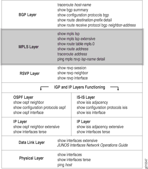 の確認
の確認
MPLS層では、LSPが起動して正しく機能しているかどうかを確認します。ネットワークがこの層で機能していない場合、LSP は設定どおりに機能しません。
図 2 は、このトピックで使用する MPLS ネットワークを示しています。
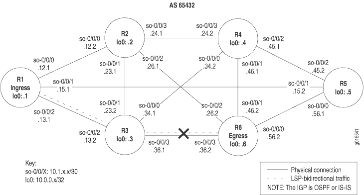 で切断されたMPLSネットワーク
図2に示すネットワークは、直接接続されているすべてのインターフェイスが、他のすべての類似したインターフェイスにパケットを受信および送信できる、完全にメッシュ化された設定です。このネットワークのLSPは、ingressルーターR1からトランジットルーターR3を経て、egressルーターR6に至るように設定されています。さらに、リバースLSPは、R6からR3からR1まで実行するように設定されており、双方向トラフィックを作成します。
しかし、この例では、 R6 から R1 へのパスがなく、リバース LSP がダウンしています。
図2に示す十字は、LSPが壊れている箇所を示しています。LSP が壊れる原因としては、MPLS プロトコルの設定ミスや、MPLS に間違って設定されたインターフェイスなどが考えられます。
図 2 に示すネットワークでは、egressルーター R6 の設定エラーにより、LSP が予想通りにネットワークを通過することができません。
MPLSレイヤーを確認するには、次の手順に従います。
- LSP の検証
- トランジットルーターでLSPルートを検証する
- イングレスルーターでLSPルートを検証する
- tracerouteコマンドによるMPLSラベルの検証
- ping コマンドによる MPLS ラベルの検証
- 適切なアクションを取る
- LSP の再検証
LSP の検証
目的
通常、LSPの検証にはshow mpls lsp extensive コマンドを使用します。ただし、LSP の状態を迅速に確認するには、show mpls lsp コマンドを使用します。LSPがダウンしている場合は、フォローアップとして拡張オプション(show mpls lsp extensive) を使用します。ネットワークに多数のLSPがある場合、名前オプション(show mpls lsp namenameまたはshow mpls lsp name name extensive)を使用して、LSPの名前を指定することを検討できます。
アクション
LSP が稼働していることを確認するには、ingressルーターから以下のコマンドの一部またはすべてを入力します。
user@host> show mpls lsp
user@host> show mpls lsp extensive
user@host> show mpls lsp name name
user@host> show mpls lsp name name extensive
サンプル出力 1
コマンド名
user@R1> show mpls lsp
Ingress LSP: 1 sessions
To              From            State Rt ActivePath       P     LSPname
10.0.0.6        10.0.0.1        Dn     0 -                       R1-to-R6
Total 1 displayed, Up 0,  Down 1

Egress LSP: 0 sessions
Total 0 displayed, Up 0, Down 0

Transit LSP: 0 sessions
Total 0 displayed, Up 0, Down 0

user@R3> show mpls lsp
Ingress LSP: 0 sessions
Total 0 displayed, Up 0, Down 0

Egress LSP: 0 sessions
Total 0 displayed, Up 0, Down 0

Transit LSP: 0 sessions
Total 0 displayed, Up 0, Down 0

user@R6> show mpls lsp
Ingress LSP: 1 sessions
To              From            State Rt ActivePath       P     LSPname
10.0.0.1        10.0.0.6        Dn     0 -                       R6-to-R1
Total 1 displayed, Up 0,  Down 1

Egress LSP: 0 sessions
Total 0 displayed, Up 0, Down 0

Transit LSP: 0 sessions
Total 0 displayed, Up 0, Down 0
サンプル出力2
コマンド名
user@R1> show mpls lsp extensive
Ingress LSP: 1 sessions

10.0.0.6
  From: 10.0.0.1, State: Dn, ActiveRoute: 0, LSPname: R1-to-R6
  ActivePath: (none)
  LoadBalance: Random
  Encoding type: Packet, Switching type: Packet, GPID: IPv4
  Primary                    State: Dn
    Will be enqueued for recomputation in 22 second(s).
    1 Nov  2 14:43:38  CSPF failed: no route toward 10.0.0.6 [175 times]
  Created: Tue Nov  2 13:18:39 2004
Total 1 displayed, Up 0, Down 1

Egress LSP: 0 sessions
Total 0 displayed, Up 0, Down 0

Transit LSP: 0 sessions
Total 0 displayed, Up 0, Down 0

user@R3> show mpls lsp extensive
Ingress LSP: 0 sessions
Total 0 displayed, Up 0, Down 0

Egress LSP: 0 sessions
Total 0 displayed, Up 0, Down 0

Transit LSP: 0 sessions
Total 0 displayed, Up 0, Down 0

user@R6> show mpls lsp extensive
Ingress LSP: 1 sessions

10.0.0.1
  From: 10.0.0.6, State: Dn, ActiveRoute: 0, LSPname: R6-to-R1
  ActivePath: (none)
  LoadBalance: Random
  Encoding type: Packet, Switching type: Packet, GPID: IPv4
  Primary                    State: Dn
    Will be enqueued for recomputation in 13 second(s).
    1 Nov  2 14:38:12  CSPF failed: no route toward 10.0.0.1 [177 times]
  Created: Tue Nov  2 13:12:22 2004
Total 1 displayed, Up 0, Down 1

Egress LSP: 0 sessions
Total 0 displayed, Up 0, Down 0

Transit LSP: 0 sessions
Total 0 displayed, Up 0, Down 0
サンプル出力 3
コマンド名
user@R1> show mpls lsp name R1-to-R6
Ingress LSP: 1 sessions
To              From            State Rt ActivePath       P     LSPname
10.0.0.6        10.0.0.1        Dn     0 -                      R1-to-R6
Total 1 displayed, Up 0, Down 1

Egress LSP: 0 sessions
Total 0 displayed, Up 0, Down 0

Transit LSP: 0 sessions
Total 0 displayed, Up 0, Down 0
サンプル出力 4
コマンド名
user@R1> show mpls lsp name R1-to-R6 extensive
Ingress LSP: 1 sessions

10.0.0.6
  From: 10.0.0.1, State: Dn, ActiveRoute: 0, LSPname: R1-to-R6
  ActivePath: (none)
  LoadBalance: Random
  Encoding type: Packet, Switching type: Packet, GPID: IPv4
  Primary                    State: Dn
    Will be enqueued for recomputation in 10 second(s).
    1 Nov  2 14:51:53 CSPF failed: no route toward 10.0.0.6[192 times]
  Created: Tue Nov  2 13:18:39 2004
Total 1 displayed, Up 0, Down 1

Egress LSP: 0 sessions
Total 0 displayed, Up 0, Down 0

Transit LSP: 0 sessions
Total 0 displayed, Up 0, Down 0
意味
サンプル出力 1 は、イングレス、トランジット、およびエグレス ルーターの LSP の状態の簡単な説明を示しています。ingress ルーターR1 とegress ルーターR6 からの出力は、 R1-to-R6 と R6-toR1の両方のLSPがダウンしていることを示しています。 R1 と R6 に LSP を設定した場合、 R1 と R6 の両方でエグレス LSP セッションが発生することが予想されます。さらに、トランジット ルーター R3 にはトランジット セッションがありません。
サンプル出力 2 には、過去の状態の履歴や LSP が失敗した理由など、LSP に関するすべての情報が表示されます。 R1 と R6 からの出力は、CSPF(Constrained Shortest Path First)アルゴリズムが失敗したため、宛先へのルートがないことを示しています。
サンプル出力 3 および 4 は、extensive オプションを使用した show mpls lsp name コマンドの出力例を示しています。この例では、MPLS層で壊れたネットワークのサンプルネットワークには 1 つの LSP のみが設定されているため、出力は show mpls lsp コマンドと非常によく似ていますMPLS。しかし、多くのLSPが設定された大規模なネットワークでは、2つのコマンドで結果が大きく異なります。
トランジットルーターでLSPルートを検証する
目的
LSP がアップしている場合、LSP ルートは mpls.0 ルーティングテーブルに表示されるはずです。MPLS は、各 LSP の次のラベルスイッチ ルーターのリストを含む MPLS パス ルーティングテーブル(mpls.0)を維持します。このルーティングテーブルは、LSPに沿って次のルーターにパケットをルーティングするためにトランジットルーターで使用されます。トランジット ルーターの出力にルートが存在しない場合は、イングレス ルーターとエグレス ルーターの MPLS プロトコル設定を確認します。
アクション
トランジットルーターでLSPルートを確認するには、トランジットルーターから次のコマンドを入力します。
user@host> show route table mpls.0
サンプル出力 1
コマンド名
user@R3> show route table mpls.0
mpls.0: 3 destinations, 3 routes (3 active, 0 holddown, 0 hidden)
+ = Active Route, - = Last Active, * = Both
0                  *[MPLS/0] 16w2d 21:52:40, metric 1
                      Receive
1                  *[MPLS/0] 16w2d 21:52:40, metric 1
                      Receive
2                  *[MPLS/0] 16w2d 21:52:40, metric 1
                      Receive
サンプル出力2
コマンド名
user@R3> show route table mpls.0
mpls.0: 7 destinations, 7 routes (7 active, 0 holddown, 0 hidden)
+ = Active Route, - = Last Active, * = Both
0                  *[MPLS/0] 16w2d 22:26:08, metric 1
                      Receive
1                  *[MPLS/0] 16w2d 22:26:08, metric 1
                      Receive
2                  *[MPLS/0] 16w2d 22:26:08, metric 1
                      Receive
100864             *[RSVP/7] 00:07:23, metric 1
                    > via so-0/0/2.0, label-switched-path R6-to-R1
100864(S=0)        *[RSVP/7] 00:07:23, metric 1
                    > via so-0/0/2.0, label-switched-path R6-to-R1
100880             *[RSVP/7] 00:07:01, metric 1
                    > via so-0/0/3.0, label-switched-path R1-to-R6
100880(S=0)        *[RSVP/7] 00:07:01, metric 1
                    > via so-0/0/3.0, label-switched-path R1-to-R6
意味
トランジット ルーター R3 からのサンプル出力 1 には、MPLS ラベル エントリーの形式で 3 つのルート エントリーが表示されています。これらの MPLS ラベルは、RFC 3032 で定義された予約済み MPLS ラベルであり、LSP の状態に関係なく、 mpls.0 ルーティングテーブルに常に存在します。RSVP によってアップストリーム ネイバーに割り当てられた受信ラベルが出力から欠落しており、LSP がダウンしていることを示しています。MPLSラベルエントリの詳細については、 LSPの使用を確認するためのチェックリストを参照してください。
対照的に、サンプル出力 2 は、正しく設定された LSP の MPLS ラベルとルートを示しています。3 つの予約済み MPLS ラベルが存在し、他の 4 つのエントリーは、RSVP によってアップストリーム ネイバーに割り当てられた受信ラベルを表しています。これらの4つのエントリは、2つのルートを表しています。MPLSヘッダーのスタック値は異なる場合があるため、ルートごとに2つのエントリーがあります。各ルートについて、2番目のエントリ 100864(S=0) と 100880(S=0) は、スタックの深さが1ではなく、追加のラベル値がパケットに含まれていることを示しています。対照的に、最初のエントリである 100864 と 100880 は、スタックの深さが1であることを示す推定S=1の値を持ち、各ラベルをその特定のパケットの最後のラベルにします。デュアルエントリーは、これが最後から2番目のルーターであることを示しています。MPLSラベルスタックの詳細については、RFC 3032、 MPLSラベルスタックエンコーディングを参照してください。
イングレスルーターでLSPルートを検証する
目的
LSP ルートが、指定されたアドレスの inet.3 ルーティングテーブルのアクティブエントリに含まれているかどうかを確認します。
アクション
LSP ルートを確認するには、ingressルーターから次のコマンドを入力します。
user@host> show route destination
サンプル出力 1
コマンド名
user@R1> show route 10.0.0.6
inet.0 : 27 destinations, 27 routes (27 active, 0 holddown, 0 hidden)
+ = Active Route, - = Last Active, * = Both
10.0.0.6/32        *[IS-IS/18] 6d 01:41:37, metric 20
                      to 10.1.12.2 via so-0/0/0.0
                    > to 10.1.15.2 via so-0/0/1.0
                      to 10.1.13.2 via so-0/0/2.0

user@R6> show route 10.0.0.1

inet.0 : 28 destinations, 28 routes (28 active, 0 holddown, 0 hidden)
+ = Active Route, - = Last Active, * = Both
10.0.0.1/32        *[IS-IS/18] 5d 01:01:38, metric 20
                      to 10.1.56.1 via so-0/0/0.0
                    > to 10.1.26.1 via so-0/0/2.0
                      to 10.1.36.1 via so-0/0/3.0
サンプル出力2
コマンド名
user@R1> show route 10.0.0.6
inet.0: 28 destinations, 28 routes (27 active, 0 holddown, 1 hidden)
+ = Active Route, - = Last Active, * = Both

10.0.0.6/32        *[IS-IS/18] 6d 02:13:42, metric 20
                      to 10.1.12.2 via so-0/0/0.0
                    > to 10.1.15.2 via so-0/0/1.0
                      to 10.1.13.2 via so-0/0/2.0

inet.3 : 1 destinations, 1 routes (1 active, 0 holddown, 0 hidden)
+ = Active Route, - = Last Active, * = Both

10.0.0.6/32        *[RSVP/7] 00:08:07, metric 20
                    > via so-0/0/2.0,  label-switched-path R1-to-R6

user@R6> show route 10.0.0.1

inet.0: 29 destinations, 29 routes (28 active, 0 holddown, 1 hidden)
+ = Active Route, - = Last Active, * = Both

10.0.0.1/32        *[IS-IS/18] 5d 01:34:03, metric 20
                      to 10.1.56.1 via so-0/0/0.0
                    > to 10.1.26.1 via so-0/0/2.0
                      to 10.1.36.1 via so-0/0/3.0

inet.3 : 1 destinations, 1 routes (1 active, 0 holddown, 0 hidden)
+ = Active Route, - = Last Active, * = Both

10.0.0.1/32        *[RSVP/7] 00:10:39, metric 20
                    >  via so-0/0/3.0, label-switched-path R6-to-R1
意味
サンプル出力 1 は、 inet.0 ルーティングテーブルのエントリーのみを示しています。LSP が機能していないため、 inet.3 ルーティングテーブルが出力から欠落しています。 inet.0 ルーティングテーブルは、内部ゲートウェイプロトコル(IGP)と境界ゲートウェイプロトコル(BGP)によってルーティング情報を格納するために使用されます。この場合、IGPは中間システム-中間システム(IS-IS)です。 inet.0 ルーティングテーブルの詳細については、 Junos MPLS アプリケーション設定ガイドを参照してください。
LSP が機能している場合、 inet.3 ルーティングテーブルに LSP を含むエントリーが表示されることが予想されます。 inet.3 ルーティングテーブルは、BGP パケットを宛先egressルーターにルーティングするためにイングレスルーターで使用されます。BGPは、ingressルーターの inet.3 ルーティングテーブルを使用して、ネクストホップアドレスの解決を支援します。BGPは、 MPLSレイヤーで切断されたMPLSネットワークに示されているネットワーク例で設定されています。
サンプル出力 2 は、LSP がアップしたときに受信する出力を示しています。出力には、 inet.0 と inet.3 の両方のルーティングテーブルが表示されており、LSP R1からR6 と R6からR1 が利用可能であることを示しています。
tracerouteコマンドによるMPLSラベルの検証
目的
ルートの BGP ネクストホップが LSP エグレスアドレスである BGP 宛先まで、パケットがたどるルートを表示します。デフォルトでは、BGPは inet.0 および inet.3 ルーティングテーブルを使用してネクストホップアドレスを解決します。BGPルートのネクストホップアドレスがegressルーターのルーターIDではない場合、トラフィックはLSPではなくIGPルートにマッピングされます。 traceroute コマンドをデバッグツールとして使用して、LSPがトラフィックの転送に使用されているかどうかを判断します。
アクション
MPLSラベルを検証するには、ingressルーターから以下のコマンドを入力します。
user@host> traceroute hostname
サンプル出力 1
コマンド名
user@R1> traceroute 100.100.6.1
traceroute to 100.100.6.1 (100.100.6.1), 30 hops max, 40 byte packets
 1  10.1.12.2 (10.1.12.2)  0.627 ms  0.561 ms  0.520 ms
 2  10.1.26.2 (10.1.26.2)  0.570 ms !N  0.558 ms !N  4.879 ms !N

user@R6> traceroute 100.100.1.1
traceroute to 100.100.1.1 (100.100.1.1), 30 hops max, 40 byte packets
 1  10.1.26.1 (10.1.26.1)  0.630 ms  0.545 ms  0.488 ms
 2  10.1.12.1 (10.1.12.1)  0.551 ms !N  0.557 ms !N  0.526 ms !N
サンプル出力2
コマンド名
user@R1> traceroute 100.100.6.1
 to 100.100.6.1 (100.100.6.1), 30 hops max, 40 byte packets
 1  10.1.13.2 (10.1.13.2)  0.866 ms  0.746 ms  0.724 ms
      MPLS Label=100912 CoS=0 TTL=1 S=1
 2  10.1.36.2 (10.1.36.2)  0.577 ms !N  0.597 ms !N  0.546 ms !N

user@R6> traceroute 100.100.1.1
traceroute to 100.100.1.1 (100.100.1.1), 30 hops max, 40 byte packets
 1  10.1.36.1 (10.1.36.1)  0.802 ms  0.716 ms  0.688 ms
      MPLS Label=100896 CoS=0 TTL=1 S=1
 2  10.1.13.1 (10.1.13.1)  0.570 ms !N  0.568 ms !N  0.546 ms !N
意味
サンプル出力 1 では、BGP トラフィックが LSP を使用していないため、MPLS ラベルが出力に表示されていないことが示されています。BGPトラフィックはLSPを使用する代わりに、IGP( MPLS層でネットワークが壊れたMPLSのネットワーク例ではIS-IS)を使用して、BGPネクストホップLSPエグレスアドレスに到達しています。Junos OSデフォルトの動作では、BGPネクストホップがLSPエグレスアドレスと等しい場合、BGPトラフィックにLSPを使用します。
サンプル出力 2 は、正しく設定された LSP の出力例です。出力にはMPLSラベルが表示されており、BGPトラフィックがLSPを使用してBGPネクストホップに到達していることを示しています。
ping コマンドによる MPLS ラベルの検証
目的
特定のLSPにpingを実行する際、エコー要求がMPLSパケットとしてLSPを介して送信されていることを確認します。
アクション
MPLSラベルを検証するには、ingressルーターから以下のコマンドを入力して、egressルーターにpingを実行します。
user@host> ping mpls rsvp lsp-name detail
次に例を示します。
user@R1> ping mpls rsvp R1-to-R6 detail
サンプル出力 1
コマンド名
user@R1> ping mpls rsvp R1-to-R6 detail
LSP R1-to-R6 - LSP has no active path, exiting.

user@R6> ping mpls rsvp R6-to-R1 detail
LSP R6-to-R1 - LSP has no active path, exiting.
サンプル出力2
コマンド名
user@R1> traceroute 10.0.0.6
traceroute to 10.0.0.6 (10.0.0.6), 30 hops max, 40 byte packets
 1  10.1.15.2 (10.1.15.2)  0.708 ms  0.613 ms  0.576 ms
 2  10.0.0.6 (10.0.0.6)  0.763 ms  0.708 ms  0.700 ms

user@R1> ping mpls rsvp R1-to-R6 detail
Request for seq 1, to interface 69, label 100880
Reply for seq 1, return code: Egress-ok
Request for seq 2, to interface 69, label 100880
Reply for seq 2, return code: Egress-ok
Request for seq 3, to interface 69, label 100880
Reply for seq 3, return code: Egress-ok
Request for seq 4, to interface 69, label 100880
Reply for seq 4, return code: Egress-ok
Request for seq 5, to interface 69, label 100880
Reply for seq 5, return code: Egress-ok

--- lsping statistics ---
5 packets transmitted, 5 packets received, 0% packet loss

user@R6> ping mpls rsvp R6-to-R1 detail
Request for seq 1, to interface 70, label 100864
Reply for seq 1, return code: Egress-ok
Request for seq 2, to interface 70, label 100864
Reply for seq 2, return code: Egress-ok
Request for seq 3, to interface 70, label 100864
Reply for seq 3, return code: Egress-ok
Request for seq 4, to interface 70, label 100864
Reply for seq 4, return code: Egress-ok
Request for seq 5, to interface 70, label 100864
Reply for seq 5, return code: Egress-ok

--- lsping statistics ---
5 packets transmitted, 5 packets received, 0% packet loss
意味
サンプル出力 1 は、LSP にエコー要求を転送するためのアクティブなパスがないことを示しており、LSP がダウンしていることを示しています。
サンプル出力 2 は、LSP が立ち上がっていてパケットを転送しているときに受信する出力の例です。
適切なアクションを取る
問題点
説明
調査で発生したエラーに応じて、問題を修正するための適切なアクションを実行する必要があります。この例では、egressルーターR6の[edit protocols mpls]階層レベルでインターフェイスが正しく設定されていません。
ソリューション
この例のエラーを修正するには、次の手順に従います。
-
egress ルーターR6のMPLSプロトコル設定でインターフェイスをアクティブにします。
user@R6> edit
user@R6# edit protocols mpls
[edit protocols mpls]
user@R6# show
user@R6# activate interface so-0/0/3.0
-
設定を確認し、コミットします。
[edit protocols mpls]
user@R6# show
user@R6# commit
出力例
user@R6> edit
Entering configuration mode

[edit]
user@R6# edit protocols mpls

[edit protocols mpls]
user@R6# show
label-switched-path R6-to-R1 {
    to 10.0.0.1;
}
inactive: interface so-0/0/0.0;
inactive: interface so-0/0/1.0;
inactive: interface so-0/0/2.0;
inactive: interface so-0/0/3.0; <<< Incorrectly configured interface

[edit protocols mpls]
user@R6#  activate interface so-0/0/3

[edit protocols mpls]
user@R6# show
label-switched-path R6-to-R1 {
    to 10.0.0.1;
}
inactive: interface so-0/0/0.0;
inactive: interface so-0/0/1.0;
inactive: interface so-0/0/2.0;
interface so-0/0/3.0; <<< Correctly configured interface

[edit protocols mpls]
user@R6# commit
commit complete
意味
サンプル出力は、egressルーターR6で誤って設定されたインターフェイスso-0/0/3.0が[edit protocols mpls]階層レベルでアクティブ化されていることを示しています。これでLSPを立ち上げることができます。
LSP の再検証
目的
エラーを修正するために適切なアクションを実行した後、LSP を再度チェックして、BGP レイヤーの問題が解決されたことを確認する必要があります。
アクション
LSPを再度確認するには、イングレス、トランジット、およびエグレスの各ルータから次のコマンドを入力します。
user@host> show mpls lsp extensive
出力例
コマンド名
user@R1> show mpls lsp extensive
Ingress LSP: 1 sessions

10.0.0.6
  From: 10.0.0.1,  State: Up ,  ActiveRoute: 1 ,  LSPname: R1-to-R6
  ActivePath:  (primary)
  LoadBalance: Random
  Encoding type: Packet, Switching type: Packet, GPID: IPv4
 *Primary                    State: Up
    Computed ERO (S [L] denotes strict [loose] hops): (CSPF metric: 20)
 10.1.13.2 S 10.1.36.2 S
    Received RRO (ProtectionFlag 1=Available 2=InUse 4=B/W 8=Node 10=SoftPreempt):
          10.1.13.2 10.1.36.2
    6 Nov  2 15:48:52 Selected as active path
    5 Nov  2 15:48:52 Record Route:  10.1.13.2 10.1.36.2
    4 Nov  2 15:48:52 Up
    3 Nov  2 15:48:52 Originate Call
    2 Nov  2 15:48:52 CSPF: computation result accepted
    1 Nov  2 15:48:22 CSPF failed: no route toward 10.0.0.6[308 times]
  Created: Tue Nov  2 13:18:39 2004
Total 1 displayed, Up 1, Down 0

Egress LSP: 1 sessions

10.0.0.1
  From: 10.0.0.6,  LSPstate: Up , ActiveRoute: 0
   LSPname: R6-to-R1 , LSPpath: Primary
  Suggested label received: -, Suggested label sent: -
  Recovery label received: -, Recovery label sent: -
  Resv style: 1 FF, Label in: 3, Label out: -
  Time left:  159, Since: Tue Nov  2 15:48:30 2004
  Tspec: rate 0bps size 0bps peak Infbps m 20 M 1500
  Port number: sender 1 receiver 39106 protocol 0
  PATH rcvfrom: 10.1.13.2 (so-0/0/2.0) 10 pkts
  Adspec: received MTU 1500
  PATH sentto: localclient
  RESV rcvfrom: localclient
  Record route: 10.1.36.2 10.1.13.2 <self>
Total 1 displayed, Up 1, Down 0

Transit LSP: 0 sessions
Total 0 displayed, Up 0, Down 0

user@R3> show mpls lsp extensive
Ingress LSP: 0 sessions
Total 0 displayed, Up 0, Down 0

Egress LSP: 0 sessions
Total 0 displayed, Up 0, Down 0

Transit LSP: 2 sessions

10.0.0.1
  From: 10.0.0.6, LSPstate: Up, ActiveRoute: 1
  LSPname: R6-to-R1, LSPpath: Primary
  Suggested label received: -, Suggested label sent: -
  Recovery label received: -, Recovery label sent: 3
  Resv style: 1 FF, Label in: 100864, Label out: 3
  Time left:  123, Since: Tue Nov  2 15:35:41 2004
  Tspec: rate 0bps size 0bps peak Infbps m 20 M 1500
  Port number: sender 1 receiver 39106 protocol 0
  PATH rcvfrom: 10.1.36.2 (so-0/0/3.0) 10 pkts
  Adspec: received MTU 1500 sent MTU 1500
  PATH sentto: 10.1.13.1 (so-0/0/2.0) 10 pkts
  RESV rcvfrom: 10.1.13.1 (so-0/0/2.0) 10 pkts
  Explct route: 10.1.13.1
  Record route: 10.1.36.2 <self> 10.1.13.1

10.0.0.6
  From: 10.0.0.1, LSPstate: Up, ActiveRoute: 1
  LSPname: R1-to-R6, LSPpath: Primary
  Suggested label received: -, Suggested label sent: -
  Recovery label received: -, Recovery label sent: 3
  Resv style: 1 FF, Label in: 100880, Label out: 3
  Time left:  145, Since: Tue Nov  2 15:36:03 2004
  Tspec: rate 0bps size 0bps peak Infbps m 20 M 1500
  Port number: sender 1 receiver 48015 protocol 0
  PATH rcvfrom: 10.1.13.1 (so-0/0/2.0) 10 pkts
  Adspec: received MTU 1500 sent MTU 1500
  PATH sentto: 10.1.36.2 (so-0/0/3.0) 10 pkts
  RESV rcvfrom: 10.1.36.2 (so-0/0/3.0) 10 pkts
  Explct route: 10.1.36.2
  Record route: 10.1.13.1 <self> 10.1.36.2
Total 2 displayed, Up 2, Down 0

user@R6> show mpls lsp extensive
Ingress LSP: 1 sessions

10.0.0.1
  From: 10.0.0.6,  State: Up, ActiveRoute: 1, LSPname: R6-to-R1
  ActivePath:  (primary)
  LoadBalance: Random
  Encoding type: Packet, Switching type: Packet, GPID: IPv4
 *Primary                    State: Up
    Computed ERO (S [L] denotes strict [loose] hops): (CSPF metric: 20)
 10.1.36.1 S 10.1.13.1 S
    Received RRO (ProtectionFlag 1=Available 2=InUse 4=B/W 8=Node 10=SoftPreempt):
          10.1.36.1 10.1.13.1
    6 Nov  2 15:41:44 Selected as active path
    5 Nov  2 15:41:44 Record Route:  10.1.36.1 10.1.13.1
    4 Nov  2 15:41:44 Up
    3 Nov  2 15:41:44 Originate Call
    2 Nov  2 15:41:44 CSPF: computation result accepted
    1 Nov  2 15:41:14 CSPF failed: no route toward 10.0.0.1[306 times]
  Created: Tue Nov  2 13:12:21 2004
Total 1 displayed, Up 1, Down 0

Egress LSP: 1 sessions

10.0.0.6
  From: 10.0.0.1,  LSPstate: Up,  ActiveRoute: 0
   LSPname: R1-to-R6 , LSPpath: Primary
  Suggested label received: -, Suggested label sent: -
  Recovery label received: -, Recovery label sent: -
  Resv style: 1 FF, Label in: 3, Label out: -
  Time left:  157, Since: Tue Nov  2 15:42:06 2004
  Tspec: rate 0bps size 0bps peak Infbps m 20 M 1500
  Port number: sender 1 receiver 48015 protocol 0
  PATH rcvfrom: 10.1.36.1 (so-0/0/3.0) 11 pkts
  Adspec: received MTU 1500
  PATH sentto: localclient
  RESV rcvfrom: localclient
  Record route: 10.1.13.1 10.1.36.1 <self>
Total 1 displayed, Up 1, Down 0

Transit LSP: 0 sessions
Total 0 displayed, Up 0, Down 0
意味
ingress ルーターR1 からのサンプル出力1は、LSP R1-to-R6 に R6 へのアクティブなルートがあり、状態がupであることを示しています。
トランジット ルーター R3 からのサンプル出力 2 では、 R1 から R6 と R6 から R1 の 2 つのトランジット LSP セッションが存在することがわかります。両方のLSPが立ち上がっています。
egress ルーターR6 からのサンプル出力3は、LSPが稼働しており、アクティブなルートがプライマリルートであることを示しています。LSP はこれで、 R1 から R3 から R6 までの予想通りのパスに沿ってネットワークを通過し、リバース LSP は R6 から R3 から R1 へとネットワークを通過しています。
ノードリンク保護が起動していることを確認する
目的
ノードリンク保護を設定した後、バイパスパスが立ち上がっていることを確認する必要があります。また、バイパスパスで保護されているLSPの数を確認することもできます。 ノードリンク保護に示されているネットワークには、 R1 と R2 (またはネクストホップ 10.0.12.14)間のリンクを保護するネクストホップバイパスと、 R2を回避するネクストネクストホップバイパスの2つのバイパスパスが立ち上がっているはずです。
アクション
ノードリンク保護(多対1バックアップ)を検証するには、ingressルーターで以下のJunos OS CLI動作モードコマンドを入力します。また、トランジットルーターやバイパスパスで使用される他のルーターでコマンドを発行すると、若干異なる情報を得ることができます。
show mpls lsp
show mpls lsp extensive
show rsvp interface
show rsvp interface extensive
show rsvp session detail
出力例
コマンド名
user@R1> show mpls lsp
Ingress LSP: 1 sessions
To              From            State Rt ActivePath       P     LSPname
192.168.5.1     192.168.1.1     Up     0 via-r2           *      lsp2-r1-to-r5
Total 1 displayed,  Up 1 , Down 0

Egress LSP: 1 sessions
To              From            State   Rt Style Labelin Labelout LSPname
192.168.1.1     192.168.5.1     Up       0  1 FF       3        -  r5-to-r1
Total 1 displayed,  Up 1 , Down 0

Transit LSP: 2 sessions
To              From            State   Rt Style Labelin Labelout LSPname
192.168.0.1     192.168.6.1      Up        0  1 FF 100464   101952  lsp1-r6-to-r0
192.168.6.1     192.168.0.1      Up        0  1 FF  100448        3  r0-to-t6
Total 2 displayed, Up 2, Down 0
意味
show mpls lspコマンドのR1からのサンプル出力には、設定済みLSPとアクティブなLSPの状態の簡単な説明が表示されており、R1がイングレス、トランジット、およびegressルーターです。すべてのLSPが立ち上がっています。R1は、LSP2-R1-to-R5のingressルーターであり、リターンLSP r5-to-r1のegressルーターです。2つのLSPがR1、lsp1-r6からr0、およびリターンLSP r0からt6を通過します。LSPの詳細については、show mpls lsp コマンドを発行するときにextensiveオプションを含めます。
出力例
user@R1> show mpls lsp extensive
Ingress LSP: 1 sessions

192.168.5.1
  From: 192.168.1.1,  State: Up , ActiveRoute: 0,  LSPname: lsp2-r1-to-r5
  ActivePath: via-r2 (primary)
   Node/Link protection desired
  LoadBalance: Random
  Encoding type: Packet, Switching type: Packet, GPID: IPv4
 *Primary   via-r2           State: Up
    SmartOptimizeTimer: 180
    Computed ERO (S [L] denotes strict [loose] hops): (CSPF metric: 3)
 10.0.12.14 S 10.0.24.2 S 10.0.45.2 S
    Received RRO (ProtectionFlag 1=Available 2=InUse 4=B/W 8=Node 10=SoftPreempt):
          10.0.12.14(Label=101872) 10.0.24.2(Label=101360) 10.0.45.2(Label=3)
    11 Jul 11 14:30:58 Link-protection Up
   10 Jul 11 14:28:28 Selected as active path
    [...Output truncated...]
  Created: Tue Jul 11 14:22:58 2006
Total 1 displayed, Up 1, Down 0

Egress LSP: 1 sessions

192.168.1.1
  From: 192.168.5.1,  LSPstate: Up, ActiveRoute: 0
   LSPname: r5-to-r1, LSPpath: Primary
  Suggested label received: -, Suggested label sent: -
  Recovery label received: -, Recovery label sent: -
  Resv style: 1 FF, Label in: 3, Label out: -
  Time left:  146, Since: Tue Jul 11 14:28:36 2006
  Tspec: rate 0bps size 0bps peak Infbps m 20 M 1500
  Port number: sender 1 receiver 29228 protocol 0
  PATH rcvfrom: 10.0.12.14 (fe-0/1/0.0) 362 pkts
  Adspec: received MTU 1500
  PATH sentto: localclient
  RESV rcvfrom: localclient
  Record route: 10.0.45.2 10.0.24.2 10.0.12.14 <self>
Total 1 displayed, Up 1, Down 0

Transit LSP: 2 sessions

192.168.0.1
  From: 192.168.6.1,  LSPstate: Up, ActiveRoute: 0
   LSPname: lsp1-r6-to-r0, LSPpath: Primary
  Suggested label received: -, Suggested label sent: -
  Recovery label received: -, Recovery label sent: 101952
  Resv style: 1 SE, Label in: 100464, Label out: 101952
  Time left:  157, Since: Tue Jul 11 14:31:38 2006
  Tspec: rate 0bps size 0bps peak Infbps m 20 M 1500
  Port number: sender 1 receiver 11131 protocol 0
   Node/Link protection desired
   Type: Node/Link protected LSP, using Bypass->10.0.12.14->10.0.24.2
      1 Jul 11 14:31:38 Node protection up, using Bypass->10.0.12.14->10.0.24.2
  PATH rcvfrom: 10.0.16.2 (so-0/0/3.0) 509 pkts
  Adspec: received MTU 1500 sent MTU 1500
  PATH sentto: 10.0.12.14 (fe-0/1/0.0) 356 pkts
  RESV rcvfrom: 10.0.12.14 (fe-0/1/0.0) 358 pkts
  Explct route: 10.0.12.14 10.0.24.2 10.0.45.2 10.0.50.2
  Record route: 10.0.16.2 <self> 10.0.12.14 10.0.24.2 10.0.45.2 10.0.50.2

192.168.6.1
  From: 192.168.0.1,  LSPstate: Up, ActiveRoute: 0
  LSPname: r0-to-t6, LSPpath: Primary
  Suggested label received: -, Suggested label sent: -
  Recovery label received: -, Recovery label sent: 3
  Resv style: 1 FF, Label in: 100448, Label out: 3
  Time left:  147, Since: Tue Jul 11 14:31:36 2006
  Tspec: rate 0bps size 0bps peak Infbps m 20 M 1500
  Port number: sender 1 receiver 23481 protocol 0
  PATH rcvfrom: 10.0.12.14 (fe-0/1/0.0) 358 pkts
  Adspec: received MTU 1500 sent MTU 1500
  PATH sentto: 10.0.16.2 (so-0/0/3.0) 350 pkts
  RESV rcvfrom: 10.0.16.2 (so-0/0/3.0) 323 pkts
  Explct route: 10.0.16.2
  Record route: 10.0.50.2 10.0.45.2 10.0.24.2 10.0.12.14 <self> 10.0.16.2
Total 2 displayed, Up 2, Down 0
意味
show mpls lsp extensiveコマンドのR1からのサンプル出力には、R1がイングレス、エグレス、またはトランジットルーターであるすべてのLSPに関する詳細情報が表示され、過去の状態の全履歴とLSPが失敗した理由も含まれています。すべてのLSPが立ち上がっています。主な 2 つの LSP lsp2-r1-to-r5 と lsp1-r6-to-r0 にはノードリンク保護が備わっており、これは出力のイングレスおよびトランジット セクションにあるノード/リンク保護の望ましいフィールドで示されています。出力のイングレスセクションのリンク保護アップフィールドには、lsp2-r1-to-r5にリンク保護がアップしていることが示されています。出力のトランジットセクションのType: Node/Link protected LSPフィールドには、lsp1-r6-to-r0でノードリンク保護が立ち上がっており、障害が発生した場合はバイパスLSP Bypass->10.0.12.14->10.0.24.2が使用されることが示されています。
出力例
user@R1> show rsvp interface
RSVP interface: 4 active
                  Active Subscr- Static      Available   Reserved    Highwater
Interface   State resv   iption  BW          BW          BW          mark
fe-0/1/0.0  Up         2    100%  100Mbps     100Mbps     0bps        0bps
fe-0/1/1.0  Up         1   100%  100Mbps     100Mbps     0bps        0bps
fe-0/1/2.0  Up         0   100%  100Mbps     100Mbps     0bps        0bps
so-0/0/3.0  Up         1   100%  155.52Mbps  155.52Mbps  0bps        0bps
意味
show rsvp interfaceコマンドのR1からのサンプル出力には、4つのインターフェイスでRSVP(Up)が有効になっていることが示されています。インターフェイスfe-0/1/0.0には、2つのメインLSP、lsp1-r6-to-r0およびlsp2-r1-to-r5のセッションを示す可能性のある2つのアクティブなRSVP予約(Active resv)があります。インターフェイスfe-0/1/0.0はR1とR2間の接続インターフェイスであり、両方のLSPはfe-0/1/0.0を介する厳密なパスで構成されています。インターフェイスfe-0/1/0.0で何が起こっているかの詳細については、show rsvp interface extensive コマンドを発行してください。
出力例
user@R1> show rsvp interface extensive
RSVP interface: 3 active
fe-0/1/0.0 Index 67, State Ena/Up
  NoAuthentication, NoAggregate, NoReliable, LinkProtection
  HelloInterval 9(second)
  Address 10.0.12.13
  ActiveResv 2, PreemptionCnt 0, Update threshold 10%
  Subscription 100%,
  bc0 = ct0, StaticBW 100Mbps
  ct0: StaticBW 100Mbps, AvailableBW 100Mbps
    MaxAvailableBW 100Mbps = (bc0*subscription)
    ReservedBW [0] 0bps[1] 0bps[2] 0bps[3] 0bps[4] 0bps[5] 0bps[6] 0bps[7] 0bps
   Protection: On, Bypass: 2, LSP: 2, Protected LSP: 2, Unprotected LSP: 0
      2 Jul 14 14:49:40 New bypass Bypass->10.0.12.14
      1 Jul 14 14:49:34 New bypass Bypass->10.0.12.14->10.0.24.2
     Bypass: Bypass->10.0.12.14, State: Up, Type: LP, LSP: 0, Backup: 0
      3 Jul 14 14:49:42 Record Route:  10.0.17.14 10.0.27.1
      2 Jul 14 14:49:42 Up
      1 Jul 14 14:49:42 CSPF: computation result accepted
     Bypass: Bypass->10.0.12.14->10.0.24.2, State: Up, Type: NP, LSP: 2, Backup:0
      4 Jul 14 14:50:04 Record Route:  10.0.17.14 10.0.79.2 10.0.59.1 10.0.45.1
      3 Jul 14 14:50:04 Up
      2 Jul 14 14:50:04 CSPF: computation result accepted
      1 Jul 14 14:49:34 CSPF failed: no route toward 10.0.24.2
[...Output truncated...]
意味
show rsvp interface extensiveコマンドのR1からのサンプル出力には、すべてのRSVPインターフェイス(3)上のアクティビティに関する詳細情報が表示されます。ただし、fe-0/1/0.0の出力のみが表示されます。保護が有効になっており(保護:オン)、2つのバイパスパス(バイパス:2)が2つのLSP(保護LSP:2)を保護しています。保護されていないLSP:0フィールドで示されているように、すべてのLSPが保護されています。最初のバイパスBypass->10.0.12.14は、R1とR2 fe-0/1/0.0の間のリンクを保護するリンク保護バイパス(タイプ:LP)です。2番目のバイパスパス10.0.12.14->10.0.24.2はノードリンクで保護されたLSPで、ノード障害時にR2を回避します。
出力例
user@R1> show rsvp session detail
Ingress RSVP: 2 sessions

192.168.4.1
  From: 192.168.1.1,  LSPstate: Up, ActiveRoute: 0
   LSPname: Bypass->10.0.12.14->10.0.24.2
  Suggested label received: -, Suggested label sent: -
  Recovery label received: -, Recovery label sent: 102000
  Resv style: 1 SE, Label in: -, Label out: 102000
  Time left:    -, Since: Tue Jul 11 14:30:53 2006
  Tspec: rate 0bps size 0bps peak Infbps m 20 M 1500
  Port number: sender 1 receiver 60120 protocol 0
   Type: Bypass LSP
    Number of data route tunnel through: 2
    Number of RSVP session tunnel through: 0
  PATH rcvfrom: localclient
  Adspec: sent MTU 1500
  Path MTU: received 1500
  PATH sentto: 10.0.17.14 (fe-0/1/1.0) 336 pkts
  RESV rcvfrom: 10.0.17.14 (fe-0/1/1.0) 310 pkts
   Explct route: 10.0.17.14 10.0.79.2 10.0.59.1 10.0.45.1
  Record route: <self> 10.0.17.14 10.0.79.2 10.0.59.1 10.0.45.1

192.168.5.1
  From: 192.168.1.1,  LSPstate: Up, ActiveRoute: 0
   LSPname: lsp2-r1-to-r5, LSPpath: Primary
  Suggested label received: -, Suggested label sent: -
  Recovery label received: -, Recovery label sent: 101872
  Resv style: 1 SE, Label in: -, Label out: 101872
  Time left:    -, Since: Tue Jul 11 14:28:28 2006
  Tspec: rate 0bps size 0bps peak Infbps m 20 M 1500
  Port number: sender 2 receiver 60118 protocol 0
   Node/Link protection desired
  Type: Node/Link protected LSP
  PATH rcvfrom: localclient
  Adspec: sent MTU 1500
  Path MTU: received 1500
  PATH sentto: 10.0.12.14 (fe-0/1/0.0) 344 pkts
  RESV rcvfrom: 10.0.12.14 (fe-0/1/0.0) 349 pkts
   Explct route: 10.0.12.14 10.0.24.2 10.0.45.2
  Record route: <self> 10.0.12.14 10.0.24.2 10.0.45.2
Total 2 displayed, Up 2, Down 0

Egress RSVP: 1 sessions

192.168.1.1
  From: 192.168.5.1,  LSPstate: Up, ActiveRoute: 0
  LSPname: r5-to-r1, LSPpath: Primary
  Suggested label received: -, Suggested label sent: -
  Recovery label received: -, Recovery label sent: -
  Resv style: 1 FF, Label in: 3, Label out: -
  Time left:  147, Since: Tue Jul 11 14:28:36 2006
  Tspec: rate 0bps size 0bps peak Infbps m 20 M 1500
  Port number: sender 1 receiver 29228 protocol 0
  PATH rcvfrom: 10.0.12.14 (fe-0/1/0.0) 348 pkts
  Adspec: received MTU 1500
  PATH sentto: localclient
  RESV rcvfrom: localclient
  Record route: 10.0.45.2 10.0.24.2 10.0.12.14 <self>
Total 1 displayed, Up 1, Down 0

Transit RSVP: 2 sessions

192.168.0.1
  From: 192.168.6.1,  LSPstate: Up, ActiveRoute: 0
   LSPname: lsp1-r6-to-r0, LSPpath: Primary
  Suggested label received: -, Suggested label sent: -
  Recovery label received: -, Recovery label sent: 101952
  Resv style: 1 SE, Label in: 100464, Label out: 101952
  Time left:  134, Since: Tue Jul 11 14:31:38 2006
  Tspec: rate 0bps size 0bps peak Infbps m 20 M 1500
  Port number: sender 1 receiver 11131 protocol 0
   Node/Link protection desired
  Type: Node/Link protected LSP
  PATH rcvfrom: 10.0.16.2 (so-0/0/3.0) 488 pkts
  Adspec: received MTU 1500 sent MTU 1500
  PATH sentto: 10.0.12.14 (fe-0/1/0.0) 339 pkts
  RESV rcvfrom: 10.0.12.14 (fe-0/1/0.0) 343 pkts
   Explct route: 10.0.12.14 10.0.24.2 10.0.45.2 10.0.50.2
  Record route: 10.0.16.2 <self> 10.0.12.14 10.0.24.2 10.0.45.2 10.0.50.2

192.168.6.1
  From: 192.168.0.1,  LSPstate: Up, ActiveRoute: 0
  LSPname: r0-to-t6, LSPpath: Primary
  Suggested label received: -, Suggested label sent: -
  Recovery label received: -, Recovery label sent: 3
  Resv style: 1 FF, Label in: 100448, Label out: 3
  Time left:  158, Since: Tue Jul 11 14:31:36 2006
  Tspec: rate 0bps size 0bps peak Infbps m 20 M 1500
  Port number: sender 1 receiver 23481 protocol 0
  PATH rcvfrom: 10.0.12.14 (fe-0/1/0.0) 344 pkts
  Adspec: received MTU 1500 sent MTU 1500
  PATH sentto: 10.0.16.2 (so-0/0/3.0) 337 pkts
  RESV rcvfrom: 10.0.16.2 (so-0/0/3.0) 310 pkts
  Explct route: 10.0.16.2
  Record route: 10.0.50.2 10.0.45.2 10.0.24.2 10.0.12.14 <self> 10.0.16.2
Total 2 displayed, Up 2, Down 0
意味
R1からのサンプル出力には、R1でアクティブなRSVPセッションに関する詳細な情報が表示されています。すべてのセッションが立ち上がっており、イングレスセッションが2つ、エグレスセッションが1つ、トランジットセッションが2つあります。
イングレスセクション内では、最初のセッションはバイパスパスであり、タイプ:バイパスLSPフィールドで示されています。2番目のセッションは、タイプ:ノード/リンク保護LSPフィールドで示されているように、R1を起点とする保護LSP(lsp2-r1-to-r5)です。
まとめ
MPLS(MPLS)LSP(ラベルスイッチ パス)リンク保護とノードリンク保護は、LSP トラフィックの再ルーティングに必要な時間を短縮するために使用される施設ベースの方法です。これらの保護メソッドは、もう1つのJunos OS LSP保護メソッドである高速再ルートと比較されることがよくあります。
高速再ルートが LSP を 1 対 1 で保護するのに対し、リンク保護とノードリンク保護は、単一の論理バイパス LSP を使用して複数の LSP を保護します。リンク保護はリンクに対して堅牢なバックアップサポートを提供し、ノードリンク保護はノードまたはリンクを迂回します。どちらのタイプの保護も他のベンダーの機器との相互運用性を考慮して設計されています。このような機能性から、リンク保護とノードリンク保護は、MPLS対応ネットワークにおける拡張性、冗長性、パフォーマンスの面で優れた選択肢となります。
関連情報
MPLSの高速再ルートおよびMPLS保護メソッドの詳細については、以下を参照してください。
-
Junosユーザーガイド
-
Junos MPLSアプリケーション構成ガイド
-
セメリア、 チャック。 MPLSトラフィックエンジニアリングのためのRSVPシグナリング拡張 ホワイト ペーパー、2002年
-
セメリア、 チャック。 IPの依存性 ネットワークリンクとノード保護ホワイト ペーパー、2002年
-
RFC 4090、 LSPトンネル向けのRSVP-TEへの高速再ルート拡張
リンク保護が起動していることを確認する
目的
リンク保護を確認するときは、バイパスLSPが起動していることを確認する必要があります。バイパスで保護されているLSPの数を確認することもできます。 多対1またはリンク保護で示したネットワークでは、 R1 と R2の間のリンク、またはネクストホップ 10.0.12.14と、リンクを通過する2つのLSP、 lsp2-r1-to-r5 および lsp1-r6-to-r0を保護するために、バイパスパスを稼働させる必要があります。
アクション
リンク保護(多対1バックアップ)を確認するには、ingressルーターで以下のJunos OS CLI動作モードコマンドを入力します。
user@host> show mpls lsp extensive
user@host> show rsvp session detail
user@host> show rsvp interface
出力例
コマンド名
user@R1> show mpls lsp extensive | no-more
Ingress LSP: 1 sessions

192.168.5.1
  From: 192.168.1.1, State: Up, ActiveRoute: 0, LSPname: lsp2-r1-to-r5
  ActivePath:  via-r2 (primary)
   Link protection desired
  LoadBalance: Random
  Encoding type: Packet, Switching type: Packet, GPID: IPv4
 *Primary   via-r2           State: Up
    SmartOptimizeTimer: 180
    Computed ERO (S [L] denotes strict [loose] hops): (CSPF metric: 3)
 10.0.12.14 S 10.0.24.2 S 10.0.45.2 S
     Received RRO (ProtectionFlag 1=Available 2=InUse 4=B/W 8=Node  10=SoftPreempt):
          10.0.12.14(Label=101264) 10.0.24.2(Label=100736) 10.0.45.2(Label=3)
    6 Jun 16 14:06:33  Link-protection Up
    5 Jun 16 14:05:39 Selected as active path
    4 Jun 16 14:05:39 Record Route:  10.0.12.14(Label=101264) 10.0.24.2(Label=100736) 10.0.45.2(Label=3)
    3 Jun 16 14:05:39 Up
    2 Jun 16 14:05:39 Originate Call
    1 Jun 16 14:05:39 CSPF: computation result accepted
  Created: Fri Jun 16 14:05:38 2006
Total 1 displayed, Up 1, Down 0

[...Output truncated...]

Transit LSP: 2 sessions

192.168.0.1
  From: 192.168.6.1, LSPstate: Up, ActiveRoute: 0
   LSPname: lsp1-r6-to-r0, LSPpath: Primary
  Suggested label received: -, Suggested label sent: -
  Recovery label received: -, Recovery label sent: 101296
  Resv style: 1 SE, Label in: 100192, Label out: 101296
  Time left:  116, Since: Mon Jun 19 10:26:32 2006
  Tspec: rate 0bps size 0bps peak Infbps m 20 M 1500
  Port number: sender 1 receiver 58739 protocol 0
  Link protection desired
  Type: Link protected LSP, using Bypass->10.0.12.14
      1 Jun 19 10:26:32 Link protection up, using Bypass->10.0.12.14
  PATH rcvfrom: 10.0.16.2 (so-0/0/3.0) 579 pkts
  Adspec: received MTU 1500 sent MTU 1500
  PATH sentto: 10.0.12.14 (fe-0/1/0.0) 474 pkts
  RESV rcvfrom: 10.0.12.14 (fe-0/1/0.0) 501 pkts
  Explct route: 10.0.12.14 10.0.24.2 10.0.45.2 10.0.50.2
  Record route: 10.0.16.2 <self> 10.0.12.14 10.0.24.2 10.0.45.2 10.0.50.2
[...Output truncated...]
意味
ingress ルーターR1 からの出力例は、 lsp2-r1-to-r5 と lsp1-r6-to-r0 がリンク保護を起動しており、両方のLSPがバイパスパス 10.0.12.14を使用していることを示しています。ただし、 show mpls lsp コマンドはバイパスパスをリストしません。バイパスパスの詳細については、 show rsvp session コマンドを使用します。
出力例
user@R1> show rsvp session detail
Ingress RSVP: 2 sessions
192.168.2.1
  From: 192.168.1.1, LSPstate: Up, ActiveRoute: 0
   LSPname: Bypass->10.0.12.14
  Suggested label received: -, Suggested label sent: -
  Recovery label received: -, Recovery label sent: 101456
  Resv style: 1 SE, Label in: -, Label out: 101456
  Time left:    -, Since: Fri May 26 18:38:09 2006
  Tspec: rate 0bps size 0bps peak Infbps m 20 M 1500
  Port number: sender 1 receiver 18709 protocol 0
   Type: Bypass LSP
     Number of data route tunnel through: 2
    Number of RSVP session tunnel through: 0
  PATH rcvfrom: localclient
  Adspec: sent MTU 1500
  Path MTU: received 1500
  PATH sentto: 10.0.17.14 (fe-0/1/1.0) 51939 pkts
  RESV rcvfrom: 10.0.17.14 (fe-0/1/1.0) 55095 pkts
   Explct route: 10.0.17.14 10.0.27.1
  Record route: <self> 10.0.17.14 10.0.27.1

192.168.5.1
  From: 192.168.1.1, LSPstate: Up, ActiveRoute: 0
  LSPname: lsp2-r1-to-r5, LSPpath: Primary
  Suggested label received: -, Suggested label sent: -
  Recovery label received: -, Recovery label sent: 101264
  Resv style: 1 SE, Label in: -, Label out: 101264
  Time left:    -, Since: Fri Jun 16 14:05:39 2006
  Tspec: rate 0bps size 0bps peak Infbps m 20 M 1500
  Port number: sender 1 receiver 18724 protocol 0
  Link protection desired
  Type: Link protected LSP
  PATH rcvfrom: localclient
  Adspec: sent MTU 1500
  Path MTU: received 1500
  PATH sentto: 10.0.12.14 (fe-0/1/0.0) 8477 pkts
  RESV rcvfrom: 10.0.12.14 (fe-0/1/0.0) 8992 pkts
  Explct route: 10.0.12.14 10.0.24.2 10.0.45.2
  Record route: <self> 10.0.12.14 10.0.24.2 10.0.45.2
Total 2 displayed, Up 2, Down 0

Egress RSVP: 1 sessions

192.168.1.1
  From: 192.168.5.1, LSPstate: Up, ActiveRoute: 0
  LSPname: r5-to-r1, LSPpath: Primary
  Suggested label received: -, Suggested label sent: -
  Recovery label received: -, Recovery label sent: -
  Resv style: 1 FF, Label in: 3, Label out: -
  Time left:  159, Since: Mon May 22 22:08:16 2006
  Tspec: rate 0bps size 0bps peak Infbps m 20 M 1500
  Port number: sender 1 receiver 64449 protocol 0
  PATH rcvfrom: 10.0.17.14 (fe-0/1/1.0) 63145 pkts
  Adspec: received MTU 1500
  PATH sentto: localclient
  RESV rcvfrom: localclient
  Record route: 10.0.59.1 10.0.79.2 10.0.17.14 <self>
Total 1 displayed, Up 1, Down 0
Transit RSVP: 2 sessions
192.168.0.1
  From: 192.168.6.1, LSPstate: Up, ActiveRoute: 0
  LSPname: lsp1-r6-to-r0, LSPpath: Primary
  Suggested label received: -, Suggested label sent: -
  Recovery label received: -, Recovery label sent: 101296
  Resv style: 1 SE, Label in: 100192, Label out: 101296
  Time left:  129, Since: Mon Jun 19 10:26:32 2006
  Tspec: rate 0bps size 0bps peak Infbps m 20 M 1500
  Port number: sender 1 receiver 58739 protocol 0
  Link protection desired
  Type: Link protected LSP
  PATH rcvfrom: 10.0.16.2 (so-0/0/3.0) 3128 pkts
  Adspec: received MTU 1500 sent MTU 1500
  PATH sentto: 10.0.12.14 (fe-0/1/0.0) 2533 pkts
  RESV rcvfrom: 10.0.12.14 (fe-0/1/0.0) 2685 pkts
  Explct route: 10.0.12.14 10.0.24.2 10.0.45.2 10.0.50.2
  Record route: 10.0.16.2 <self> 10.0.12.14 10.0.24.2 10.0.45.2 10.0.50.2

192.168.6.1
  From: 192.168.0.1, LSPstate: Up, ActiveRoute: 0
  LSPname: r0-to-r6, LSPpath: Primary
  Suggested label received: -, Suggested label sent: -
  Recovery label received: -, Recovery label sent: 3
  Resv style: 1 FF, Label in: 100128, Label out: 3
  Time left:  143, Since: Thu May 25 12:30:26 2006
  Tspec: rate 0bps size 0bps peak Infbps m 20 M 1500
  Port number: sender 1 receiver 4111 protocol 0
  PATH rcvfrom: 10.0.17.14 (fe-0/1/1.0) 57716 pkts
  Adspec: received MTU 1500 sent MTU 1500
  PATH sentto: 10.0.16.2 (so-0/0/3.0) 54524 pkts
  RESV rcvfrom: 10.0.16.2 (so-0/0/3.0) 50534 pkts
  Explct route: 10.0.16.2
  Record route: 10.0.50.2 10.0.59.1 10.0.79.2 10.0.17.14 <self> 10.0.16.2
Total 2 displayed, Up 2, Down 0
意味
ingressルーター R1 からの出力例は、 R1 のイングレス、エグレス、およびトランジット LSP を示しています。一部の情報は、 show mpls lsp コマンドにある情報と似ています。ただし、リンク保護はRSVP機能であるため、バイパスパスに関する情報が提供されます。バイパスパスは、 タイプ フィールドで示されているように、保護されたインターフェイスの個別のRSVPイングレスセッションとして表示されます。
バイパスパス名は自動的に生成されます。デフォルトでは、名前は Bypass > interface-addressと表示され、インターフェイスアドレスは次のダウンストリームルーターのインターフェイス(10.0.12.14)です。セッションの明示的なルート 10.0.17.14 10.0.27.1 では、 R7 がトランジットノード、 R2 がエグレスノードとして示されています。
出力のイングレスRSVPセクション内で、R1(lsp2-r1-to-r5)で発信されたLSPがリンク保護を要求していることが示されています。ダウンストリームリンクを保護するためにバイパスパスが設定されているため、リンク保護LSPフィールドで示されているように、lsp2-r1-to-r5がバイパスに関連付けられます。
出力のエグレスセクションには、保護されていないリターンLSP r5-to-r1が表示されます。
出力のトランジットセクションは、lsp1-r6-to-r0によって要求されたリンク保護を示しています。ダウンストリームリンクを保護するためにバイパスパスが設定されているため、リンク保護LSPフィールドで示されているように、lsp1-r6-to-r0がバイパスに関連付けられます。また、出力のトランジットセクションには、保護されていないリターンLSP r0-to-r6も含まれています。
出力例
user@R1> show rsvp interface
RSVP interface: 4 active
                  Active Subscr- Static      Available   Reserved    Highwater
Interface   State resv   iption  BW          BW          BW          mark
fe-0/1/0.0  Up          2    100%  100Mbps     100Mbps     0bps        35Mbps
fe-0/1/1.0  Up          1    100%  100Mbps     100Mbps     0bps        0bps
fe-0/1/2.0  Up          0    100%  100Mbps     100Mbps     0bps        0bps
so-0/0/3.0  Up          1    100%  155.52Mbps  155.52Mbps  0bps        0bps
意味
ingressルーター R1からの出力例は、R1で設定されたインターフェイスを通過するLSPの数を示しています。アクティブresvフィールドには、各インターフェイスのLSPの数が表示されます。例えば、R1 と R2 の間のインターフェイス fe-0/1/0.0 には、lsp1-r6-to-r0 と lsp2-r1-to-r5 の 2 つのアクティブな予約があります。R1とR7の間のインターフェイスfe-0/1/1.0には、バイパス(10.0.12.14)があります。R6とR1間のインターフェイスfe-0/1/2.0にはLSP予約がありません。R6とR1の間のインターフェイスso-0/0/3.0には、1つのLSP予約lsp1-r6-to-r0があります。
ワンツーワンバックアップの検証
目的
ネットワーク内のingressルーターと他のルーターを調べることで、ワンツーワンバックアップが確立されていることを確認できます。
アクション
ワンツーワンバックアップを検証するには、以下のJunos OS CLI運用モードコマンドを入力します。
user@host> show mpls lsp ingress extensive
user@host> show rsvp session
出力例
コマンド名
以下のサンプル出力は、ingressルーター R1 からのものです。
user@R1> show mpls lsp ingress extensive
Ingress LSP: 1 sessions

192.168.5.1
  From: 192.168.1.1, State: Up, ActiveRoute: 0, LSPname: r1-to-r5
  ActivePath: via-r2 (primary)
   FastReroute desired
  LoadBalance: Random
  Encoding type: Packet, Switching type: Packet, GPID: IPv4
 *Primary   via-r2           State: Up
    SmartOptimizeTimer: 180
    Computed ERO (S [L] denotes strict [loose] hops): (CSPF metric: 3)
 10.0.12.14 S 10.0.24.2 S 10.0.45.2 S
     Received RRO  (ProtectionFlag 1=Available 2=InUse 4=B/W 8=Node 10=SoftPreempt):
           10.0.12.14(flag=9) 10.0.24.2(flag=1) 10.0.45.2
     8 May 11 14:51:46 Fast-reroute Detour Up
     7 May 11 14:50:55 Record Route:  10.0.12.14(flag=9) 10.0.24.2(flag=1)  10.0.45.2
    6 May 11 14:50:55 Record Route:  10.0.12.14(flag=9) 10.0.24.2 10.0.45.2
    5 May 11 14:50:52 Selected as active path
    4 May 11 14:50:52 Record Route:  10.0.12.14 10.0.24.2 10.0.45.2
    3 May 11 14:50:52 Up
    2 May 11 14:50:52 Originate Call
    1 May 11 14:50:52 CSPF: computation result accepted
  Created: Thu May 11 14:50:52 2006
Total 1 displayed, Up 1, Down 0
意味
R1からのサンプル出力は、FastReroute目的のオブジェクトがLSPのパスメッセージに含まれていることを示しています。これにより、R1はLSPのアクティブなパスを選択し、R2を回避するための迂回パスを確立できます。
8行目、「 高速再ルート迂回アップ 」は、迂回路が機能していることを示しています。6行目と7行目は、トランジット ルーターR2 と R4 が迂回パスを確立したことを示しています。
R2、10.0.12.14には(flag=9)が含まれており、ダウンストリームノードとリンクでノード保護が利用可能であることを示しています。R4、10.0.24.2には(flag=1)が含まれており、リンク保護が次のダウンストリームリンクで使用可能であることを示しています。この場合、ノードが保護できないegressルーターR5であるため、R4はダウンストリームリンクのみを保護できます。フラグの詳細については、『Junosユーザーガイド』を参照してください。
show mpls lsp extensive コマンドの出力には、迂回路の実際のパスは表示されません。迂回パスで使用される実際のリンクを確認するには、show rsvp session ingress detailコマンドを使用する必要があります。
出力例
次のサンプル出力は、ワンツーワン バックアップ迂回路に示されているネットワーク内のingressルーターR1からのものです。
user@R1> show rsvp session ingress detail
Ingress RSVP: 1 sessions

192.168.5.1
  From: 192.168.1.1,  LSPstate: Up,  ActiveRoute: 0
  LSPname: r1-to-r5, LSPpath: Primary
  Suggested label received: -, Suggested label sent: -
  Recovery label received: -, Recovery label sent: 100848
  Resv style: 1 FF, Label in: -, Label out: 100848
  Time left:    -, Since: Thu May 11 14:17:15 2006
  Tspec: rate 0bps size 0bps peak Infbps m 20 M 1500
  Port number: sender 1 receiver 9228 protocol 0
   FastReroute desired
  PATH rcvfrom: localclient
  Adspec: sent MTU 1500
  Path MTU: received 1500
  PATH sentto: 10.0.12.14 (fe-0/1/0.0) 35 pkts
  RESV rcvfrom: 10.0.12.14 (fe-0/1/0.0) 25 pkts
  Explct route: 10.0.12.14 10.0.24.2 10.0.45.2
  Record route: <self> 10.0.12.14 10.0.24.2 10.0.45.2
     Detour is Up
    Detour Tspec: rate 0bps size 0bps peak Infbps m 20 M 1500
    Detour adspec: sent MTU 1500
    Path MTU: received 1500
    Detour PATH sentto: 10.0.17.14 (fe-0/1/1.0) 23 pkts
    Detour RESV rcvfrom: 10.0.17.14 (fe-0/1/1.0) 20 pkts
     Detour Explct route: 10.0.17.14 10.0.79.2 10.0.59.1
    Detour Record route: <self> 10.0.17.14 10.0.79.2 10.0.59.1
    Detour Label out: 100848
Total 1 displayed, Up 1, Down 0
意味
R1からのサンプル出力は、メインLSPのRSVPセッションを示しています。迂回パスが確立され、迂回がアップになります。迂回路の物理パスは、迂回手順ルートに表示されます。迂回パスは、R7とR9をトランジットルーターとして使用して、egressルーターであるR5に到達します。
出力例
次のサンプル出力は、 ワンツーワン バックアップ迂回路に示されているネットワークの最初のトランジット ルーター R2 からのものです。
user@R2> show rsvp session transit detail
Transit RSVP: 1 sessions

192.168.5.1
  From: 192.168.1.1, LSPstate: Up, ActiveRoute: 1
  LSPname: r1-to-r5, LSPpath: Primary
  Suggested label received: -, Suggested label sent: -
  Recovery label received: -, Recovery label sent: 100448
  Resv style: 1 FF, Label in: 100720, Label out: 100448
  Time left:  126, Since: Wed May 10 16:12:21 2006
  Tspec: rate 0bps size 0bps peak Infbps m 20 M 1500
  Port number: sender 5 receiver 9216 protocol 0
   FastReroute desired
  PATH rcvfrom: 10.0.12.13 (fe-0/1/0.0) 173 pkts
  Adspec: received MTU 1500 sent MTU 1500
  PATH sentto: 10.0.24.2 (so-0/0/1.0) 171 pkts
  RESV rcvfrom: 10.0.24.2 (so-0/0/1.0) 169 pkts
  Explct route: 10.0.24.2 10.0.45.2
  Record route: 10.0.12.13 <self> 10.0.24.2 10.0.45.2
     Detour is Up
    Detour Tspec: rate 0bps size 0bps peak Infbps m 20 M 1500
    Detour adspec: received MTU 1500 sent MTU 1500
    Path MTU: received 1500
    Detour PATH sentto: 10.0.27.2 (so-0/0/3.0) 169 pkts
    Detour RESV rcvfrom: 10.0.27.2 (so-0/0/3.0) 167 pkts
     Detour Explct route: 10.0.27.2 10.0.79.2 10.0.59.1
    Detour Record route: 10.0.12.13 <self> 10.0.27.2 10.0.79.2 10.0.59.1
    Detour Label out: 100736
Total 1 displayed, Up 1, Down 0
意味
R2からのサンプル出力は、迂回路が確立され(迂回路がUp)、R4を回避し、R4とR5を接続するリンク(10.0.45.2)を示しています。迂回パスは、R7(10.0.27.2)およびR9(10.0.79.2)からR5(10.0.59.1)までであり、R1からの迂回の明示的なルートとは異なります。R1はR7の10.0.17.14リンクを迂回し、R1は10.0.27.2リンクを使用しています。両方の迂回路は、R9で10.0.79.2リンクを経由してR5(10.0.59.1)に合流します。
出力例
次のサンプル出力は、 ワンツーワン バックアップ迂回路に示されているネットワークの 2 番目のトランジット ルーター R4 からのものです。
user@R4> show rsvp session transit detail
Transit RSVP: 1 sessions

192.168.5.1
  From: 192.168.1.1,  LSPstate: Up, ActiveRoute: 1
   LSPname: r1-to-r5, LSPpath: Primary
  Suggested label received: -, Suggested label sent: -
  Recovery label received: -, Recovery label sent: 3
  Resv style: 1 FF, Label in: 100448, Label out: 3
  Time left:  155, Since: Wed May 10 16:15:38 2006
  Tspec: rate 0bps size 0bps peak Infbps m 20 M 1500
  Port number: sender 5 receiver 9216 protocol 0
   FastReroute desired
  PATH rcvfrom: 10.0.24.1 (so-0/0/1.0) 178 pkts
  Adspec: received MTU 1500 sent MTU 1500
  PATH sentto: 10.0.45.2 (so-0/0/2.0) 178 pkts
  RESV rcvfrom: 10.0.45.2 (so-0/0/2.0) 175 pkts
  Explct route: 10.0.45.2
  Record route: 10.0.12.13 10.0.24.1 <self> 10.0.45.2
     Detour is Up
    Detour Tspec: rate 0bps size 0bps peak Infbps m 20 M 1500
    Detour adspec: received MTU 1500 sent MTU 1500
    Path MTU: received 1500
    Detour PATH sentto: 10.0.49.2 (so-0/0/3.0) 176 pkts
    Detour RESV rcvfrom: 10.0.49.2 (so-0/0/3.0) 175 pkts
     Detour Explct route: 10.0.49.2 10.0.59.1
     Detour Record route: 10.0.12.13 10.0.24.1 <self> 10.0.49.2 10.0.59.1
    Detour Label out: 100352
Total 1 displayed, Up 1, Down 0
意味
R4からのサンプル出力は、迂回路が確立され(迂回路がUp)、R4とR5を接続するリンク(10.0.45.2)を回避していることを示しています。迂回パスは、R9(10.0.49.2)からR5(10.0.59.1)までです。一部の情報は、R1 および R2 の出力にある情報と類似しています。ただし、迂回路の明示的なルートは異なり、R4とR9を接続するリンク(つまり-0/0/3または10.0.49.2)を経由します。
出力例
次のサンプル出力は R7からのもので、 ワンツーワンバックアップ迂回路に示されているネットワークの迂回パスで使用されます。
user@R7> show rsvp session transit detail
Transit RSVP: 1 sessions, 1 detours

192.168.5.1
  From: 192.168.1.1,  LSPstate: Up, ActiveRoute: 1
   LSPname: r1-to-r5, LSPpath: Primary
  Suggested label received: -, Suggested label sent: -
  Recovery label received: -, Recovery label sent: 100368
  Resv style: 1 FF, Label in: 100736, Label out: 100368
  Time left:  135, Since: Wed May 10 16:14:42 2006
  Tspec: rate 0bps size 0bps peak Infbps m 20 M 1500
  Port number: sender 5 receiver 9216 protocol 0
   Detour branch from 10.0.27.1, to skip 192.168.4.1, Up
    Tspec: rate 0bps size 0bps peak Infbps m 20 M 1500
    Adspec: received MTU 1500
    Path MTU: received 0
    PATH rcvfrom: 10.0.27.1 (so-0/0/3.0) 179 pkts
    Adspec: received MTU 1500 sent MTU 1500
    PATH sentto: 10.0.79.2 (so-0/0/1.0) 177 pkts
    RESV rcvfrom: 10.0.79.2 (so-0/0/1.0) 179 pkts
    Explct route: 10.0.79.2 10.0.59.1
     Record route: 10.0.12.13 10.0.27.1 <self> 10.0.79.2 10.0.59.1
     Label in: 100736, Label out: 100368
   Detour branch from 10.0.17.13, to skip 192.168.2.1, Up
    Tspec: rate 0bps size 0bps peak Infbps m 20 M 1500
    Adspec: received MTU 1500
    Path MTU: received 0
    PATH rcvfrom: 10.0.17.13 (fe-0/1/1.0) 179 pkts
    Adspec: received MTU 1500
    PATH sentto: 10.0.79.2 (so-0/0/1.0) 0 pkts
    RESV rcvfrom: 10.0.79.2 (so-0/0/1.0) 0 pkts
    Explct route: 10.0.79.2 10.0.59.1
     Record route: 10.0.17.13 <self> 10.0.79.2 10.0.59.1
     Label in: 100752, Label out: 100368
Total 1 displayed, Up 1, Down 0
意味
R7からのサンプル出力には、LSPのプライマリパスで使用される通常のトランジットルーターと同じ情報、つまりイングレスアドレス(192.168.1.1)、エグレスアドレス(192.168.5.1)、LSPの名前(r1-to-r5)が表示されます。2つの迂回パスが表示されます。1つ目はR4(192.168.4.1)を回避し、2つ目はR2(192.168.2.1)を回避します。R7 は R2 と R4 のトランジット ルーターとして使用されるため、R7 は、両方の迂回パスの同一のラベル出力値(100368)で示されるように、迂回パスを合流できます。R7がラベル値100736のR4からトラフィックを受信するか、ラベル値100752のR2からトラフィックを受信するかどうかにかかわらず、R7はラベル値100368のR5にパケットを転送します。
出力例
次のサンプル出力はR9からのものであり、 ワンツーワンバックアップ迂回路に示されているネットワークの迂回パスで使用されるルーターです。
user@R9> show rsvp session transit detail
Transit RSVP: 1 sessions, 1 detours

192.168.5.1
  From: 192.168.1.1, LSPstate: Up, ActiveRoute: 1
  LSPname: r1-to-r5, LSPpath: Primary
  Suggested label received: -, Suggested label sent: -
  Recovery label received: -, Recovery label sent: 3
  Resv style: 1 FF, Label in: 100352, Label out: 3
  Time left:  141, Since: Wed May 10 16:16:40 2006
  Tspec: rate 0bps size 0bps peak Infbps m 20 M 1500
  Port number: sender 5 receiver 9216 protocol 0
   Detour branch from 10.0.49.1, to skip 192.168.5.1, Up
    Tspec: rate 0bps size 0bps peak Infbps m 20 M 1500
    Adspec: received MTU 1500
    Path MTU: received 0
    PATH rcvfrom: 10.0.49.1 (so-0/0/3.0) 183 pkts
    Adspec: received MTU 1500 sent MTU 1500
    PATH sentto: 10.0.59.1 (so-0/0/0.0) 182 pkts
    RESV rcvfrom: 10.0.59.1 (so-0/0/0.0) 183 pkts
    Explct route: 10.0.59.1
     Record route: 10.0.12.13 10.0.24.1 10.0.49.1 <self> 10.0.59.1
    Label in: 100352, Label out: 3
   Detour branch from 10.0.27.1, to skip 192.168.4.1, Up
    Tspec: rate 0bps size 0bps peak Infbps m 20 M 1500
    Adspec: received MTU 1500
    Path MTU: received 0
   Detour branch from 10.0.17.13, to skip 192.168.2.1, Up
    Tspec: rate 0bps size 0bps peak Infbps m 20 M 1500
    Adspec: received MTU 1500
    Path MTU: received 0
    PATH rcvfrom: 10.0.79.1 (so-0/0/1.0) 181 pkts
    Adspec: received MTU 1500
    PATH sentto: 10.0.59.1 (so-0/0/0.0) 0 pkts
    RESV rcvfrom: 10.0.59.1 (so-0/0/0.0) 0 pkts
     Explct route: 10.0.59.1
    Record route: 10.0.12.13 10.0.27.1 10.0.79.1 <self> 10.0.59.1
     Label in: 100368,  Label out: 3
Total 1 displayed, Up 1, Down 0
意味
R9からのサンプル出力は、R9が迂回パスの最後から2番目のルーターであり、明示的なルートにはエグレスリンクアドレス(10.0.59.1)のみが含まれ、ラベルアウト値(3)はR9が最後から2番目のホップラベルポップを実行したことを示しています。また、R7がR2とR4からの迂回パスをマージしたため、10.0.27.1からの迂回ブランチにはパス情報が含まれていません。10.0.17.13からの迂回ブランチのラベルアウト値は100368であり、R7のラベルアウト値と同じ値であることに注意してください。
出力例
次のサンプル出力は、 ワンツーワン バックアップ迂回路に示されているネットワーク内のegressルーターR5からのものです。
user@R5> show rsvp session egress detail
Egress RSVP: 1 sessions, 1 detours

192.168.5.1
  From: 192.168.1.1, LSPstate: Up, ActiveRoute: 0
  LSPname: r1-to-r5, LSPpath: Primary
  Suggested label received: -, Suggested label sent: -
  Recovery label received: -, Recovery label sent: -
  Resv style: 1 FF, Label in: 3, Label out: -
  Time left:  119, Since: Thu May 11 14:44:31 2006
  Tspec: rate 0bps size 0bps peak Infbps m 20 M 1500
  Port number: sender 1 receiver 9230 protocol 0
   FastReroute desired
  PATH rcvfrom: 10.0.45.1 (so-0/0/2.0) 258 pkts
  Adspec: received MTU 1500
  PATH sentto: localclient
  RESV rcvfrom: localclient
   Record route: 10.0.12.13 10.0.24.1 10.0.45.1 <self>
   Detour branch from 10.0.49.1, to skip 192.168.5.1, Up
    Tspec: rate 0bps size 0bps peak Infbps m 20 M 1500
    Adspec: received MTU 1500
    Path MTU: received 0
   Detour branch from 10.0.27.1, to skip 192.168.4.1, Up
    Tspec: rate 0bps size 0bps peak Infbps m 20 M 1500
    Adspec: received MTU 1500
    Path MTU: received 0
   Detour branch from 10.0.17.13, to skip 192.168.2.1, Up
    Tspec: rate 0bps size 0bps peak Infbps m 20 M 1500
    Adspec: received MTU 1500
    Path MTU: received 0
    PATH rcvfrom: 10.0.59.2 (so-0/0/0.0) 254 pkts
    Adspec: received MTU 1500
    PATH sentto: localclient
    RESV rcvfrom: localclient
    Record route: 10.0.12.13 10.0.24.1 10.0.49.1 10.0.59.2 <self>
     Label in: 3, Label out: -
Total 1 displayed, Up 1, Down 0
意味
R5からの出力例は、記録ルートフィールドのメインLSPとネットワークを迂回するものを示しています。
プライマリパスが動作していることを確認する
目的
ネットワークでは、プライマリパスが利用可能であれば、常にプライマリパスを使用しなければなりません。そのため、LSPは障害発生後、設定を変更しない限り、常にプライマリパスに戻ります。障害が発生したプライマリパスの再確立を防ぐための設定の調整については、 以前に失敗したパスの使用を防ぐを参照してください。
アクション
プライマリパスが使用可能であることを確認するには、次の Junos OS コマンドラインインターフェイス(CLI)動作モードコマンドを入力します。
user@host> show mpls lsp extensive ingress
user@host> show rsvp interface
サンプル出力 1
コマンド名
user@R1> show mpls lsp extensive ingress
Ingress LSP: 1 sessions

192.168.5.1
  From: 192.168.1.1, State: Up, ActiveRoute: 0, LSPname: r1-to-r5
   ActivePath: via-r2 (primary)
  LoadBalance: Random
  Encoding type: Packet, Switching type: Packet, GPID: IPv4
 *Primary   via-r2           State: Up
     Priorities: 6 6
     Bandwidth: 35Mbps
    SmartOptimizeTimer: 180
     Computed ERO (S [L] denotes strict [loose] hops): (CSPF metric: 11)
 10.0.12.14 S 10.0.24.2 S
     Received RRO  (ProtectionFlag 1=Available 2=InUse 4=B/W 8=Node 10=SoftPreempt):
           10.0.12.14 10.0.24.2
    5 Apr 29 14:40:43 Selected as active path
    4 Apr 29 14:40:43 Record Route:  10.0.12.14 10.0.24.2
    3 Apr 29 14:40:43 Up
    2 Apr 29 14:40:43 Originate Call
    1 Apr 29 14:40:43 CSPF: computation result accepted
  Standby   via-r7           State: Dn
    SmartOptimizeTimer: 180
        No computed ERO.
  Created: Sat Apr 29 14:40:43 2006
Total 1 displayed, Up 1, Down 0
サンプル出力2
コマンド名
user@R1> show rsvp interface
RSVP interface: 3 active
                  Active Subscr- Static      Available   Reserved    Highwater
Interface   State resv   iption  BW          BW          BW          mark
fe-0/1/0.0  Up         2   100%   100Mbps      100Mbps     0bps        0bps
fe-0/1/1.0  Up         1   100%   100Mbps      100Mbps     0bps        0bps
so-0/0/3.0  Up         1   100%   155.52Mbps   155.52Mbps  0bps        0bps
意味
サンプル出力1は、LSPが動作しており、R2(10.0.12.14)とR4(10.0.24.2)をトランジットルーターとして、プライマリパス(via-r2)を使用していることを示しています。優先度の値は、セットアップとホールドで同じです(6 6)。優先度 0 は最高(ベスト)優先度で、7 は最低(ワースト)優先度です。設定と保留優先度のJunos OSのデフォルトは7:0です。一部のLSPが他のLSPよりも重要でない限り、デフォルトを維持するのは良いことです。プリエンプションループを回避するために、保留優先度よりも優れた設定優先度を設定することはできず、結果的にコミットが失敗します。
セカンダリパスが確立されていることを確認する
目的
セカンダリパスが standby ステートメントで設定されている場合、セカンダリパスは アップ されていても アクティブではないはずです。プライマリパスに障害が発生した場合、アクティブになります。 standby ステートメントなしで設定されたセカンダリパスは、プライマリパスが失敗しない限り、表示されることはありません。セカンダリパスが正しく設定されており、プライマリパスに障害が発生した場合に表示されるかどうかをテストするには、プライマリパスへのリンクまたはノードを非アクティブにして、 show mpls lsp lsp-path-name extensive コマンドを発行する必要があります。
アクション
セカンダリパスが確立されていることを確認するには、次のJunos OS CLI運用モードコマンドを入力します。
出力例
user@R1> show mpls lsp extensive
出力例
コマンド名
次のサンプル出力は、表示前後に正しく設定されたセカンダリパスを示しています。この例では、R2のインターフェイスfe-0/1/0が非アクティブ化され、これによりvia-r2経由のプライマリパスがダウンします。ingressルーター R1 は、トラフィックを r7 経由のセカンダリ パスに切り替えます。
user@R1> show mpls lsp extensive
Ingress LSP: 1 sessions

192.168.5.1
  From: 192.168.1.1, State: Up, ActiveRoute: 0, LSPname: r1-to-r5
  ActivePath: via-r2 (primary)
  LoadBalance: Random
  Encoding type: Packet, Switching type: Packet, GPID: IPv4
  *Primary   via-r2           State: Up
    Priorities: 6 6
    Bandwidth: 35Mbps
    SmartOptimizeTimer: 180
     Computed ERO (S [L] denotes strict [loose] hops): (CSPF metric: 3)
 10.0.12.14 S 10.0.24.2 S 10.0.45.2 S
    Received RRO (ProtectionFlag 1=Available 2=InUse 4=B/W 8=Node 10=SoftPreempt):
          10.0.12.14 10.0.24.2 10.0.45.2
    5 Apr 29 14:40:43 Selected as active path
    4 Apr 29 14:40:43 Record Route:  10.0.12.14 10.0.24.2
    3 Apr 29 14:40:43 Up
    2 Apr 29 14:40:43 Originate Call
    1 Apr 29 14:40:43 CSPF: computation result accepted
   Secondary via-r7           State: Dn
    SmartOptimizeTimer: 180
        No computed ERO.
  Created: Sat Apr 29 14:40:43 2006
Total 1 displayed, Up 1, Down 0

[edit interfaces]
user@R2# deactivate fe-0/1/0

[edit interfaces]
user@R2# show
inactive: fe-0/1/0 {
    unit 0 {
        family inet {
            address 10.0.12.14/30;
        }
        family iso;
        family mpls;
    }
}

user@R1> show mpls lsp name r1-to-r4 extensive
Ingress LSP: 1 sessions

192.168.4.1
  From: 192.168.1.1, State: Up, ActiveRoute: 0, LSPname: r1-to-r4
   ActivePath: via-r7 (secondary)
  LoadBalance: Random
  Encoding type: Packet, Switching type: Packet, GPID: IPv4
   Primary   via-r2           State: Dn
    Priorities: 6 6
    Bandwidth: 35Mbps
    SmartOptimizeTimer: 180
    Will be enqueued for recomputation in 14 second(s).
   10 Apr 29 14:52:33 CSPF failed: no route toward 10.0.12.1 4[21 times]
    9 Apr 29 14:42:48 Clear Call
    8 Apr 29 14:42:48 Deselected as active
    7 Apr 29 14:42:48 Session preempted
    6 Apr 29 14:42:48 Down
    5 Apr 29 14:40:43 Selected as active path
    4 Apr 29 14:40:43 Record Route:  10.0.12.14 10.0.24.2
    3 Apr 29 14:40:43 Up
    2 Apr 29 14:40:43 Originate Call
    1 Apr 29 14:40:43 CSPF: computation result accepted
  *Standby   via-r7           State: Up
    SmartOptimizeTimer: 180
     Computed ERO  (S [L] denotes strict [loose] hops): (CSPF metric: 11)
 10.0.17.14 S 10.0.47.1 S
    Received RRO (ProtectionFlag 1=Available 2=InUse 4=B/W 8=Node 10=SoftPreempt):
          10.0.17.14 10.0.47.1
    5 Apr 29 14:42:48 Selected as active path
    4 Apr 29 14:41:12 Record Route:  10.0.17.14 10.0.47.1
    3 Apr 29 14:41:12 Up
    2 Apr 29 14:41:12 Originate Call
    1 Apr 29 14:41:12 CSPF: computation result accepted
  Created: Sat Apr 29 14:40:43 2006
Total 1 displayed, Up 1, Down 0
意味
egressルーターR1からのサンプル出力には、プライマリパスがまだアップしているため、ダウン状態で正しく設定されたスタンバイセカンダリパスが表示されます。プライマリパスにクリティカルなインターフェイス(R2のインターフェイスfe-0/1/0)が非アクティブ化されると、r2経由のプライマリパスがダウンし、r7経由のスタンバイセカンダリパスが立ち上がることで、R1がトラフィックをスタンバイセカンダリパスに切り替えることができます。
物理層の検証
目的
LSP を設定し、 show mpls lsp extensive コマンドを発行し、エラーが発生していると判断したら、ネットワークの物理層で問題の調査を開始できます。
図3 は、階層化MPLSモデルの物理層を示しています。
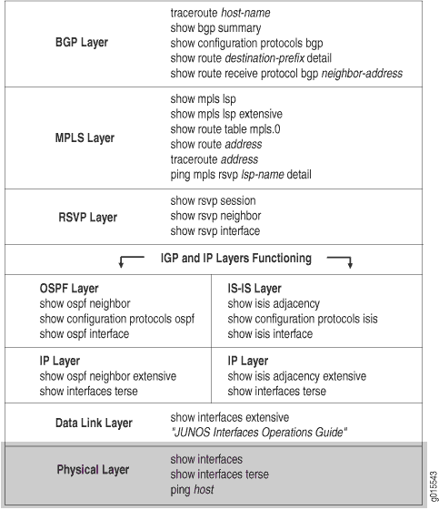
この層では、ルーターが接続されており、イングレス、エグレス、およびトランジットルーターでインターフェイスが稼働しており、正しく設定されていることを確認する必要があります。
ネットワークがこの層で機能していない場合、LSP(ラベルスイッチ パス)は設定どおりに機能しません。
図4 は、MPLSネットワークとこのトピックで説明された問題を示しています。
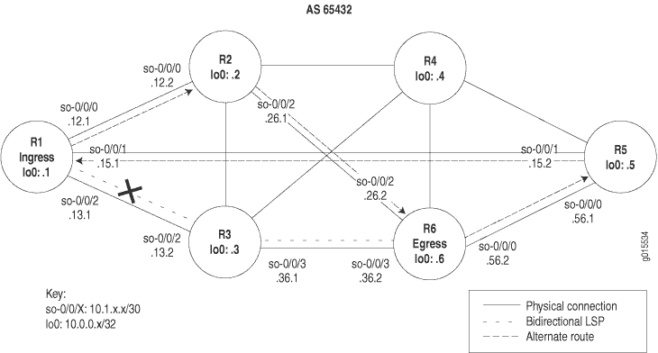
図4に示すネットワークは、直接接続されているすべてのインターフェイスが、他のすべての類似したインターフェイスにパケットを受信および送信できる、完全にメッシュ化された構成です。このネットワークのLSPは、ingressルーターR1からトランジットルーターR3を経て、egressルーターR6に至るように設定されています。さらに、リバースLSPは、R6からR3からR1まで実行するように設定されており、双方向トラフィックを作成します。
しかし、この例では、トラフィックは設定されたLSPを使用しません。代わりに、トラフィックは R1 から R2 を経て R6 に至る代替ルートを使用し、逆方向の場合は R6 から R5 を経由して R1 に至る代替ルートを使用します。
設定された LSP ではなく、代替ルートが使用される状況に気づいたら、物理層が正しく機能していることを確認します。ルーターが接続されていないか、イングレス、エグレス、またはトランジット ルーターでインターフェイスが正しく設定されていないことが判明する場合があります。
図4に示す十字は、ingressルーターR1の設定エラーによりLSPが壊れている箇所を示しています。
物理層を確認するには、次の手順に従います。
LSP の検証
目的
通常、LSPの検証にはshow mpls lsp extensive コマンドを使用します。ただし、LSP の状態を迅速に確認するには、show mpls lsp コマンドを使用します。LSP がダウンしている場合は、フォローアップとして拡張オプション(show mpls lsp extensive) を使用します。ネットワークに多数のLSPがある場合、名前オプション(show mpls lsp namenameまたはshow mpls lsp namename extensive)を使用して、LSPの名前を指定することを検討できます。
アクション
LSP が稼働しているかどうかを確認するには、ingressルーターから次のコマンドを入力します。
user@ingress-router> show mpls lsp extensive
出力例
コマンド名
user@R1> show mpls lsp extensive
Ingress LSP: 1 sessions

10.0.0.6
  From: 10.0.0.1, State: Up, ActiveRoute: 1, LSPname: R1-to-R6
  ActivePath:  (primary)
  LoadBalance: Random
  Encoding type: Packet, Switching type: Packet, GPID: IPv4
 *Primary                    State: Up
    Computed ERO (S [L] denotes strict [loose] hops): (CSPF metric: 20)
 10.1.12.2 S 10.1.26.2  S
    Received RRO (ProtectionFlag 1=Available 2=InUse 4=B/W 8=Node 10=SoftPreempt):
          10.1.12.2 10.1.26.2
   99 Sep 18 14:19:04 CSPF: computation result accepted
    98 Sep 18 14:19:04 CSPF: link down/deleted
   10.1.13.1(R1.00/10.0.0.1)->10.1.13.2(R3.00/10.0.0.3)
   97 Sep 18 14:19:01 Record Route:  10.1.12.2 10.1.26.2
   96 Sep 18 14:19:01 Up
   95 Sep 18 14:19:01 Clear Call
   94 Sep 18 14:19:01 CSPF: computation result accepted
   93 Sep 18 14:19:01 MPLS label allocation failure
   92 Sep 18 14:19:01 Down
   91 Aug 17 12:22:52 Selected as active path
   90 Aug 17 12:22:52 Record Route:  10.1.13.2 10.1.36.2
   89 Aug 17 12:22:52 Up
   [...Output truncated...]
  Created: Sat Jul 10 18:18:44 2004
Total 1 displayed, Up 1, Down 0

Egress LSP: 1 sessions

10.0.0.1
  From: 10.0.0.6, LSPstate: Up, ActiveRoute: 0
  LSPname: R6-to-R1, LSPpath: Primary
  Suggested label received: -, Suggested label sent: -
  Recovery label received: -, Recovery label sent: -
  Resv style: 1 FF, Label in: 3, Label out: -
  Time left:  144, Since: Tue Aug 17 12:23:14 2004
  Tspec: rate 0bps size 0bps peak Infbps m 20 M 1500
  Port number: sender 1 receiver 39024 protocol 0
  PATH rcvfrom: 10.1.15.2 (so-0/0/1.0) 67333 pkts
  Adspec: received MTU 1500
  PATH sentto: localclient
  RESV rcvfrom: localclient
  Record route:  10.1.56.2 10.1.15.2 <self>
Total 1 displayed, Up 1, Down 0

Transit LSP: 0 sessions
Total 0 displayed, Up 0, Down 0
意味
ingressルーターR1からの出力例は、LSPが設定されたパスではなく代替パスを使用していることを示しています。LSP の設定パスは、R1 から R3 から R6 であり、リバース LSP の場合、R6 から R3 から R1 に設定されています。LSP が使用する代替パスは、R1 から R2 から R6 まで、逆 LSP の場合は R6 から R5 から R1 です。
ルーター接続の確認
目的
パケットがパケット損失率0%で送受信されているかどうかを調べることで、適切なイングレス、トランジット、およびエグレスルーターが機能していることを確認します。
アクション
ルーターが接続されていることを確認するには、イングレスルーターとトランジットルーターから次のコマンドを入力します。
user@host> ping host
出力例
コマンド名
user@R1> ping 10.0.0.3 count 3
PING 10.0.0.3 (10.0.0.3): 56 data bytes
64 bytes from 10.0.0.3: icmp_seq=0 ttl=254 time=0.859 ms
64 bytes from 10.0.0.3: icmp_seq=1 ttl=254 time=0.746 ms
64 bytes from 10.0.0.3: icmp_seq=2 ttl=254 time=0.776 ms

--- 10.0.0.3 ping statistics ---
3 packets transmitted, 3 packets received, 0% packet loss
round-trip min/avg/max/stddev = 0.746/0.794/0.859/0.048 ms

user@R3>  ping 10.0.0.6 count 3
PING 10.0.0.6 (10.0.0.6): 56 data bytes
64 bytes from 10.0.0.6: icmp_seq=0 ttl=255 time=0.968 ms
64 bytes from 10.0.0.6: icmp_seq=1 ttl=255 time=3.221 ms
64 bytes from 10.0.0.6: icmp_seq=2 ttl=255 time=0.749 ms

--- 10.0.0.6 ping statistics ---
3 packets transmitted, 3 packets received, 0% packet loss
round-trip min/avg/max/stddev = 0.749/1.646/3.221/1.117 ms
意味
サンプル出力では、ingressルーター R1 がトランジット ルーター R3 からパケットを受信し、トランジット ルーターがegressルーターからパケットを受信していることを示しています。したがって、LSP 内のルーターは接続されています。
インターフェースの検証
目的
family mplsステートメントでインターフェイスが正しく設定されていることを確認します。
アクション
関連するインターフェイスが稼働しており、正しく設定されていることを確認するには、イングレス、トランジット、およびエグレスの各ルータから次のコマンドを入力します。
user@host> show interfaces terse
user@host> show configuration interfaces type-fpc/pic/port
出力例
コマンド名
user@R1> show interfaces so* terse
Interface               Admin Link Proto Local                 Remote
so-0/0/0                up    up
so-0/0/0.0              up    up   inet  10.1.12.1/30
                                   iso
                                   mpls
so-0/0/1                up    up
so-0/0/1.0              up    up   inet  10.1.15.1/30
                                   iso
                                   mpls
so-0/0/2                up    up
so-0/0/2.0              up    up   inet  10.1.13.1/30
                                   iso   <<< family mpls is missing
so-0/0/3                up    down

user@R1>  show configuration interfaces so-0/0/2
unit 0 {
    family inet {
        address 10.1.13.1/30;
    }
    family iso; <<<  family mpls is missing
}
意味
サンプル出力は、ingressルーター上のインターフェイスso-0/0/2.0に[edit interfaces type-fpc/pic/port]階層レベルでfamily mplsステートメントが設定されていないことを示しており、インターフェイスがLSPをサポートするように正しく設定されていないことを示しています。LSP が [edit protocols mpls] 階層レベルで正しく設定されています。
トランジットルーターとegressルーター(図示せず)からの出力は、これらのルーターのインターフェイスが正しく設定されていることを示しています。
適切なアクションを取る
問題点
説明
調査で発生したエラーに応じて、問題を修正するための適切なアクションを実行する必要があります。以下の例では、欠落していた family mpls ステートメントが、ingressルーター R1の設定に含まれています。
ソリューション
この例のエラーを修正するには、以下のコマンドを入力します。
[edit interfaces                type-fpc/pic/port]
user@R1# set family mpls
user@R1# show
user@R1# commit
出力例
[edit interfaces so-0/0/2 unit 0]
user@R1# set family mpls

[edit interfaces so-0/0/2 unit 0]
user@R1# show
family inet {
    address 10.1.13.1/30;
}
family iso;
family mpls;

[edit interfaces so-0/0/2 unit 0]
user@R1# commit
commit complete
意味
ingressルーター R1 からの出力例は、インターフェイス so-0/0/2.0 に対して family mpls ステートメントが正しく設定され、LSP が元の設定どおりに機能していることを示しています。
LSP の再検証
目的
エラーを修正するために適切なアクションを実行した後、LSP を再度チェックして、物理層の問題が解決されたことを確認する必要があります。
アクション
LSP がアップしており、想定通りにネットワークを通過していることを確認するには、以下のコマンドを入力します。
user@host> show mpls lsp extensive
サンプル出力 1
コマンド名
user@R1> show mpls lsp extensive
Ingress LSP: 1 sessions

10.0.0.6
  From: 10.0.0.1, State: Up, ActiveRoute: 1, LSPname: R1-to-R6
  ActivePath:  (primary)
  LoadBalance: Random
  Encoding type: Packet, Switching type: Packet, GPID: IPv4
 *Primary                    State: Up
    Computed ERO (S [L] denotes strict [loose] hops): (CSPF metric: 20)
  10.1.13.2 S 10.1.36.2 S
    Received RRO (ProtectionFlag 1=Available 2=InUse 4=B/W 8=Node 10=SoftPreempt):
          10.1.13.2 10.1.36.2
   112 Sep 21 16:27:33 Record Route:  10.1.13.2 10.1.36.2
   111 Sep 21 16:27:33 Up
   110 Sep 21 16:27:33 CSPF: computation result accepted
   109 Sep 21 16:27:33 CSPF: link down/deleted 10.1.12.1(R1.00/10.0.0.1)->10.1.12.2(R2.00/10.0.0.2)
   108 Sep 21 16:27:33 CSPF: link down/deleted 10.1.15.1(R1.00/10.0.0.1)->10.1.15.2(R5.00/10.0.0.5)
   [Output truncated...]
  Created: Sat Jul 10 18:18:44 2004
Total 1 displayed, Up 1, Down 0

Egress LSP: 1 sessions

10.0.0.1
  From: 10.0.0.6, LSPstate: Up, ActiveRoute: 0
  LSPname: R6-to-R1, LSPpath: Primary
  Suggested label received: -, Suggested label sent: -
  Recovery label received: -, Recovery label sent: -
  Resv style: 1 FF, Label in: 3, Label out: -
  Time left:  149, Since: Tue Sep 21 16:29:43 2004
  Tspec: rate 0bps size 0bps peak Infbps m 20 M 1500
  Port number: sender 2 receiver 39024 protocol 0
  PATH rcvfrom: 10.1.13.2 (so-0/0/2.0) 7 pkts
  Adspec: received MTU 1500
  PATH sentto: localclient
  RESV rcvfrom: localclient
   Record route: 10.1.36.2 10.1.13.2 <self>
Total 1 displayed, Up 1, Down 0

Transit LSP: 0 sessions
Total 0 displayed, Up 0, Down 0
サンプル出力2
コマンド名
[edit protocols mpls]
user@R1# show
label-switched-path R1-to-R6 {
    to 10.0.0.6;
}
interface fxp0.0 {
    disable;
}
inactive: interface so-0/0/0.0;
inactive: interface so-0/0/1.0;
interface so-0/0/2.0;
意味
ingressルーター R1 からのサンプル出力 1 は、LSP が 現在、R1 から R3 を経由して R6 へ、そして逆 LSP は、 R6 から R3 を経由して R1 へ、予想されるパスに沿ってネットワークを通過していることを示しています。
ingressルーター R1 からのサンプル出力 2 は、 R1 インターフェイス so-0/0/0.0 および so-0/0/1.0 で MPLS が非アクティブ化されているため、LSP が意図したパスを取ることを余儀なくされていることを示しています。これらのインターフェイスが非アクティブ化されていなかった場合、たとえ設定が正しいとしても、LSP は代替パスを介してネットワークを通過します。
データリンク層のチェック
目的
ラベルスイッチパス(LSP)を設定し、 show mpls lsp extensive コマンドを発行し、エラーがあると判断した後、エラーが物理層にないことが分かる場合があります。引き続き、ネットワークのデータリンク層で問題を調査します。
図5 は、階層化MPLSモデルのデータリンク層を示しています。
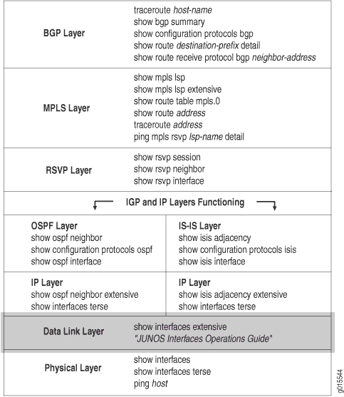 の確認
の確認
この層では、ポイントツーポイントプロトコル(PPP)やCisco High-Level Data Link Control(HDLC)などのカプセル化モードを確認する必要があります。PPP オプション(ヘッダーのカプセル化など)。フレームチェックシーケンス(FCS)サイズ。キープアライブフレームが有効または無効になっているかどうか。また、イングレス、エグレス、トランジットの各ルーターを確認してください。
図6 は、このトピックで使用するMPLSネットワークを示しています。
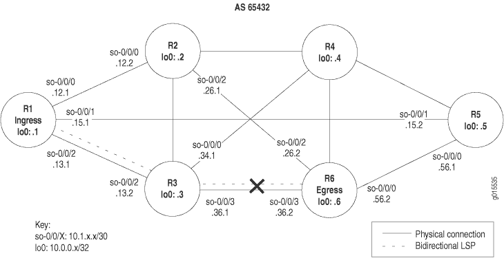 でネットワークが切断されたMPLS
図6に示すネットワークは、直接接続されているすべてのインターフェイスが、他のすべての類似したインターフェイスにパケットを受信および送信できる、完全にメッシュ化された構成です。このネットワークのLSPは、ingressルーターR1からトランジットルーターR3を経て、egressルーターR6に至るように設定されています。さらに、リバースLSPは、R6からR3からR1まで実行するように設定されており、双方向トラフィックを作成します。
しかし、この例では、 R1 から R6 、 または R6 から R1 のどの方向にもパスがなく LSP がダウンしています。
データ リンク層が正しく機能していないことを確認すると、PPP または Cisco HDLC のカプセル化、PPP オプション、またはキープアライブフレームなどの不一致が見つかることがあります。
図 6 に示す十字は、ingressルーター R1 の設定エラーにより、LSP が予想通りにネットワークを通過できず、LSP が切断している場所を示しています。
データ リンク層を確認するには、次の手順に従います。
LSP の検証
目的
通常、LSPの検証にはshow mpls lsp extensive コマンドを使用します。ただし、LSP の状態を迅速に確認するには、show mpls lsp コマンドを使用します。LSP がダウンしている場合は、フォローアップとして拡張オプション(show mpls lsp extensive) を使用します。ネットワークに多数のLSPがある場合、名前オプション(show mpls lsp name nameまたはshow mpls lsp name name extensive)を使用してLSPの名前を指定することを検討できます。
アクション
LSP が稼働しているかどうかを確認するには、ingressルーターから次のコマンドを入力します。
user@host> show mpls lsp extensive
サンプル出力 1
コマンド名
user@R1> show mpls lsp extensive
Ingress LSP: 1 sessions

10.0.0.6
  From: 10.0.0.1 , State: Dn, ActiveRoute: 0,  LSPname: R1-to-R6
   ActivePath: (none)
  LoadBalance: Random
  Encoding type: Packet, Switching type: Packet, GPID: IPv4
  Primary                    State: Dn
    Will be enqueued for recomputation in 15 second(s).
    140 Sep 30 12:01:12 CSPF failed: no route toward 10.0.0.6[26 times]
   139 Sep 30 11:48:57 Deselected as active
   138 Sep 30 11:48:56 CSPF failed: no route toward 10.0.0.6
   137 Sep 30 11:48:56 Clear Call
   136 Sep 30 11:48:56 CSPF: link down/deleted
10.1.36.1(R3.00/10.0.0.3)->10.1.36.2(R6.00/10.0.0.6)
135 Sep 30 11:48:56 ResvTear received
   134 Sep 30 11:48:56 Down
   133 Sep 30 11:48:56 CSPF failed: no route toward 10.0.0.6
   132 Sep 30 11:48:56 10.1.13.2: No Route toward dest
   [...Output truncated...]
  Created: Sat Jul 10 18:18:44 2004
Total 1 displayed, Up 0, Down 1

Egress LSP: 0 sessions
Total 0 displayed, Up 0, Down 0

Transit LSP: 0 sessions
Total 0 displayed, Up 0, Down 0
意味
ingress ルーターR1 からの出力例は、参加しているLSPを示しています。イングレスLSPがダウンしており、 R1 から R6 へのパスがありません。 データリンク層で切断されたMPLSネットワークに示されているネットワークでリバースLSPが設定されているため、エグレスLSPセッションが稼働していることが予想されます。ただし、 R1 にはエグレスLSPがないため、 R6 から R1 へのLSPが機能していないことを示しています。
インターフェースの検証
目的
ネットワークトポロジーから、LSPが通過する予定の隣接するインターフェースを特定し、カプセル化タイプ、PPPオプション、FCSサイズ、およびキープアライブフレームの有効または無効の出力を調べます
このステップに進む前に、物理層をチェックして、問題が物理層にないことを確認します。
アクション
隣接するインターフェイスの機能を確認するには、関連するルーターから以下のコマンドを入力します。
user@host> show interfaces type-fpc/pic/port extensive
user@host> show interfaces type-fpc/pic/port
サンプル出力 1
コマンド名
user@R6> show interfaces so-0/0/3 extensive
Physical interface: so-0/0/3, Enabled, Physical link is Up
  Interface index: 131, SNMP ifIndex: 27, Generation: 14
   Link-level type: Cisco-HDLC , MTU: 4474, Clocking: Internal, SONET mode, Speed: OC3, Loopback: None,
   FCS: 16 , Payload scrambler: Enabled
  Device flags   : Present Running
   Interface flags: Link-Layer-Down  Point-To-Point SNMP-Traps 16384
   Link flags     : Keepalives
  Hold-times     : Up 0 ms, Down 0 ms
  Keepalive settings: Interval 10 seconds, Up-count 1, Down-count 3
  Keepalive statistics:
    Input : 0 (last seen: never)
    Output: 357 (last sent 00:00:04 ago)
  CoS queues     : 4 supported
  Last flapped   : 2004-07-21 16:03:49 PDT (10w0d 07:01 ago)
  Statistics last cleared: Never
  Traffic statistics:
   Input  bytes  :            203368873                    0 bps
   Output bytes  :            186714992                   88 bps
   Input  packets:              3641808                    0 pps
   Output packets:              3297569                    0 pps
  Input errors:
    Errors: 0, Drops: 0, Framing errors: 0, Runts: 0, Giants: 0, Bucket drops: 0,
    Policed discards: 1770, L3 incompletes: 0, L2 channel errors: 0, L2 mismatch timeouts: 0,
    HS link CRC errors: 0, HS link FIFO overflows: 0
  Output errors:
    Carrier transitions: 1, Errors: 0, Drops: 0, Aged packets: 0, HS link FIFO underflows: 0,
    MTU errors: 0
  Queue counters:       Queued packets  Transmitted packets      Dropped packets
    0 best-effort               197012               197012                    0
    1 expedited-fo                   0                    0                    0
    2 assured-forw                   0                    0                    0
    3 network-cont             3100557              3100557                    0
   SONET alarms   : None
  SONET defects  : None
  SONET PHY:            Seconds        Count   State
    PLL Lock                  0            0   OK
    PHY Light                 0            0   OK
  SONET section:
    BIP-B1                    0            0
    SEF                       1            3   OK
    LOS                       1            1   OK
    LOF                       1            1   OK
    ES-S                      1
    SES-S                     1
    SEFS-S                    1
  SONET line:
    BIP-B2                    0            0
    REI-L                     0            0
    RDI-L                     0            0   OK
    AIS-L                     0            0   OK
    BERR-SF                   0            0   OK
    BERR-SD                   0            0   OK
    ES-L                      1
    SES-L                     1
    UAS-L                     0
    ES-LFE                    0
    SES-LFE                   0
    UAS-LFE                   0
  SONET path:
    BIP-B3                    0            0
    REI-P                     0            0
    LOP-P                     0            0   OK
    AIS-P                     0            0   OK
    RDI-P                     0            0   OK
    UNEQ-P                    0            0   OK
    PLM-P                     0            0   OK
    ES-P                      1
    SES-P                     1
    UAS-P                     0
    ES-PFE                    0
    SES-PFE                   0
    UAS-PFE                   0
  Received SONET overhead:
    F1      : 0x00, J0      : 0x00, K1      : 0x00, K2      : 0x00
    S1      : 0x00, C2      : 0xcf, C2(cmp) : 0xcf, F2      : 0x00
    Z3      : 0x00, Z4      : 0x00, S1(cmp) : 0x00
  Transmitted SONET overhead:
    F1      : 0x00, J0      : 0x01, K1      : 0x00, K2      : 0x00
    S1      : 0x00, C2      : 0xcf, F2      : 0x00, Z3      : 0x00
    Z4      : 0x00
   Received path trace: R3 so-0/0/3
    52 33 20 73 6f 2d 30 2f 30 2f 33 00 00 00 00 00    R3 so-0/0/3.. ...
    00 00 00 00 00 00 00 00 00 00 00 00 00 00 00 00   ................
    00 00 00 00 00 00 00 00 00 00 00 00 00 00 00 00   ................
    00 00 00 00 00 00 00 00 00 00 00 00 00 00 0d 0a   ................
   Transmitted path trace: R6 so-0/0/3
    52 36 20 73 6f 2d 30 2f 30 2f 33 00 00 00 00 00    R6 so-0/0/3 .....
    00 00 00 00 00 00 00 00 00 00 00 00 00 00 00 00   ................
    00 00 00 00 00 00 00 00 00 00 00 00 00 00 00 00   ................
    00 00 00 00 00 00 00 00 00 00 00 00 00 00 00 00   ................
  HDLC configuration:
    Policing bucket: Disabled
    Shaping bucket : Disabled
    Giant threshold: 4484, Runt threshold: 3
  Packet Forwarding Engine configuration:
    Destination slot: 0, PLP byte: 1 (0x00)
    CoS transmit queue             Bandwidth           Buffer Priority   Limit
                              %          bps   %        bytes
    0 best-effort            95    147744000  95            0      low    none
    3 network-control         5      7776000   5            0      low    none

  Logical interface so-0/0/3.0 (Index 71) (SNMP ifIndex 28) (Generation 16)
     Flags: Device-Down  Point-To-Point SNMP-Traps  Encapsulation: Cisco-HDLC
    Traffic statistics:
     Input  bytes  :            406737746
     Output bytes  :            186714992
     Input  packets:              7283616
     Output packets:              3297569
    Local statistics:
     Input  bytes  :            203368873
     Output bytes  :            186714992
     Input  packets:              3641808
     Output packets:              3297569
    Transit statistics:
     Input  bytes  :            203368873                    0 bps
     Output bytes  :                    0                    0 bps
     Input  packets:              3641808                    0 pps
     Output packets:                    0                    0 pps
    Protocol inet, MTU: 4470, Generation: 46, Route table: 0
      Flags: None
       Addresses, Flags: Dest-route-down Is-Preferred Is-Primary
        Destination: 10.1.36.0/30, Local: 10.1.36.2, Broadcast: 10.1.36.3, Generation: 38
    Protocol iso, MTU: 4469, Generation: 47, Route table: 0
      Flags: None
    Protocol mpls, MTU: 4458, Generation: 48, Route table: 0
      Flags: None
サンプル出力2
コマンド名
user@R3> show interfaces so-0/0/3
Physical interface: so-0/0/3, Enabled, Physical link is Up
  Interface index: 131, SNMP ifIndex: 24
   Link-level type: PPP , MTU: 4474, Clocking: Internal, SONET mode, Speed: OC3, Loopback: None,  FCS: 16 ,
  Payload scrambler: Enabled
  Device flags   : Present Running
  Interface flags: Point-To-Point SNMP-Traps
   Link flags     : Keepalives
  Keepalive settings: Interval 10 seconds, Up-count 1, Down-count 3
  Keepalive: Input: 736827 (00:00:03 ago), Output: 736972 (00:00:05 ago)
  LCP state: Opened
  NCP state: inet: Opened, inet6: Not-configured, iso: Opened, mpls: Opened
  CHAP state: Not-configured
  CoS queues     : 4 supported
  Last flapped   : 2004-07-21 16:08:01 PDT (10w5d 19:57 ago)
  Input rate     : 40 bps (0 pps)
  Output rate    : 48 bps (0 pps)
  SONET alarms   : None
  SONET defects  : None

   Logical interface so-0/0/3.0 (Index 70) (SNMP ifIndex 51)
    Flags: Point-To-Point SNMP-Traps  Encapsulation: PPP
    Protocol inet, MTU: 4470
      Flags: None
      Addresses, Flags: Is-Preferred Is-Primary
        Destination: 10.1.36.0/30, Local: 10.1.36.1, Broadcast: 10.1.36.3
    Protocol iso, MTU: 4470
      Flags: None
    Protocol mpls, MTU: 4458
      Flags: None
意味
egress ルーターR6 からのサンプル出力1では、SONETアラームや障害はなく(なし)、状態はすべて OKであり、パストレースには物理リンクがアップしていることを示す遠い端(R3 so-0.0.0)が表示されています。ただし、論理リンクはダウンしており、リンクレベルのタイプはCisco HDLCです。
トランジット ルーター R3 からのサンプル出力 2 では、リンク レベル タイプが PPP であり、カプセル化タイプが一致せず、LSP がダウンしていることを示しています。
適切なアクションを取る
問題点
説明
調査で発生したエラーに応じて、問題を修正するための適切なアクションを実行する必要があります。以下の例では、カプセル化タイプが一致していません。
ソリューション
この例のエラーを修正するには、以下のコマンドを入力します。
[edit interfaces so-0/0/3]
user@R1# show
user@R1# delete encapsulation
user@R1# show
user@R1# commit
サンペル出力
[edit interfaces so-0/0/3]
user@R6# show
encapsulation cisco-hdlc;
unit 0 {
    family inet {
        address 10.1.36.2/30;
    }
    family iso;
    family mpls;
}

[edit interfaces so-0/0/3]
user@R6# delete encapsulation

[edit interfaces so-0/0/3]
user@R6# show
unit 0 {
    family inet {
        address 10.1.36.2/30;
    }
    family iso;
    family mpls;
}

[edit interfaces so-0/0/3]
user@R6# commit
commit complete
意味
egress ルーターR6 からの出力例は、Cisco HDLCがインターフェイス so-0/0/3 に正しく設定されていないため、LSPが意図したパスを使用できなかったことを示しています。 encapsulation ステートメントを削除し、設定をコミットすると、問題が修正されました。
LSP の再検証
目的
エラーを修正するために適切な処置を行った後、LSP を再度チェックして、データリンク層の問題が解決されたことを確認する必要があります。
アクション
イングレス、エグレス、およびトランジットルーターから、LSPが立ち上がっていて、期待通りにネットワークを通過していることを確認します。
user@host> show mpls lsp extensive
サンプル出力 1
コマンド名
user@R1> show mpls lsp extensive
Ingress LSP: 1 sessions

10.0.0.6
  From: 10.0.0.1 , State: Up,  ActiveRoute: 1 ,  LSPname: R1-to-R6
  ActivePath:  (primary)
  LoadBalance: Random
  Encoding type: Packet, Switching type: Packet, GPID: IPv4
 *Primary                    State: Up
    Computed ERO (S [L] denotes strict [loose] hops): (CSPF metric: 20)
  10.1.13.2 S 10.1.36.2 S
    Received RRO (ProtectionFlag 1=Available 2=InUse 4=B/W 8=Node 10=SoftPreempt):
          10.1.13.2 10.1.36.2
   145 Sep 30 12:25:01 Selected as active path
   144 Sep 30 12:25:01 Record Route:  10.1.13.2 10.1.36.2
   143 Sep 30 12:25:01 Up
   142 Sep 30 12:25:01 Originate Call
   141 Sep 30 12:25:01 CSPF: computation result accepted
   140 Sep 30 12:24:32 CSPF failed: no route toward 10.0.0.6[74 times]
   139 Sep 30 11:48:57 Deselected as active
   138 Sep 30 11:48:56 CSPF failed: no route toward 10.0.0.6
   137 Sep 30 11:48:56 Clear Call
   136 Sep 30 11:48:56 CSPF: link down/deleted 10.1.36.1(R3.00/10.0.0.3)->10.1.36.2(R6.00/10.0.0.6)
   [...Output truncated...]
  Created: Sat Jul 10 18:18:43 2004
Total 1 displayed, Up 1 , Down 0

Egress LSP: 1 sessions

10.0.0.1
  From: 10.0.0.6 , LSPstate: Up, ActiveRoute: 0
  LSPname: R6-to-R1, LSPpath: Primary
  Suggested label received: -, Suggested label sent: -
  Recovery label received: -, Recovery label sent: -
  Resv style: 1 FF, Label in: 3, Label out: -
  Time left:  134, Since: Thu Sep 30 12:24:56 2004
  Tspec: rate 0bps size 0bps peak Infbps m 20 M 1500
  Port number: sender 6 receiver 39024 protocol 0
  PATH rcvfrom: 10.1.13.2 (so-0/0/2.0) 7 pkts
  Adspec: received MTU 1500
  PATH sentto: localclient
  RESV rcvfrom: localclient
   Record route: 10.1.36.2 10.1.13.2 <self>
Total 1 displayed, Up 1, Down 0

Transit LSP: 0 sessions
Total 0 displayed, Up 0, Down 0
サンプル出力2
コマンド名
user@R6> show mpls lsp extensive
Ingress LSP: 1 sessions

10.0.0.1
  From: 10.0.0.6, State: Up, ActiveRoute: 1, LSPname: R6-to-R1
  ActivePath:  (primary)
  LoadBalance: Random
  Encoding type: Packet, Switching type: Packet, GPID: IPv4
 *Primary                    State: Up
    Computed ERO (S [L] denotes strict [loose] hops): (CSPF metric: 20)
 10.1.36.1 S 10.1.13.1 S
    Received RRO (ProtectionFlag 1=Available 2=InUse 4=B/W 8=Node 10=SoftPreempt):
          10.1.36.1 10.1.13.1
   50 Sep 30 12:24:12 Selected as active path
   49 Sep 30 12:24:12 Record Route:  10.1.36.1 10.1.13.1
   48 Sep 30 12:24:12 Up
   47 Sep 30 12:24:12 Originate Call
   46 Sep 30 12:24:12 CSPF: computation result accepted
   45 Sep 30 12:23:43 CSPF failed: no route toward 10.0.0.1[73 times]
   44 Sep 30 11:48:12 Deselected as active
   43 Sep 30 11:48:12 CSPF failed: no route toward 10.0.0.1
   42 Sep 30 11:48:12 CSPF: link down/deleted 10.1.36.2(R6.00/10.0.0.6)->10.1.36.1(R3.00/10.0.0.3)
   [...Output truncated...]
  Created: Tue Aug 17 12:18:34 2004
Total 1 displayed, Up 1, Down 0

Egress LSP: 1 sessions

10.0.0.6
  From: 10.0.0.1 , LSPstate: Up, ActiveRoute: 0
  LSPname: R1-to-R6, LSPpath: Primary
  Suggested label received: -, Suggested label sent: -
  Recovery label received: -, Recovery label sent: -
  Resv style: 1 FF, Label in: 3, Label out: -
  Time left:  159, Since: Thu Sep 30 12:24:16 2004
  Tspec: rate 0bps size 0bps peak Infbps m 20 M 1500
  Port number: sender 19 receiver 44251 protocol 0
  PATH rcvfrom: 10.1.36.1 (so-0/0/3.0) 4 pkts
  Adspec: received MTU 1500
  PATH sentto: localclient
  RESV rcvfrom: localclient
   Record route: 10.1.13.1 10.1.36.1 <self>
Total 1 displayed, Up 1, Down 0

Transit LSP: 0 sessions
Total 0 displayed, Up 0, Down 0
サンプル出力 3
コマンド名
user@R3> show mpls lsp extensive
Ingress LSP: 0 sessions
Total 0 displayed, Up 0, Down 0

Egress LSP: 0 sessions
Total 0 displayed, Up 0, Down 0

Transit LSP: 2 sessions

10.0.0.1
  From: 10.0.0.6 , LSPstate: Up, ActiveRoute: 1
  LSPname: R6-to-R1, LSPpath: Primary
  Suggested label received: -, Suggested label sent: -
  Recovery label received: -, Recovery label sent: 3
  Resv style: 1 FF, Label in: 100176, Label out: 3
  Time left:  143, Since: Thu Sep 30 12:21:25 2004
  Tspec: rate 0bps size 0bps peak Infbps m 20 M 1500
  Port number: sender 6 receiver 39024 protocol 0
  PATH rcvfrom: 10.1.36.2 (so-0/0/3.0) 10 pkts
  Adspec: received MTU 1500 sent MTU 1500
  PATH sentto: 10.1.13.1 (so-0/0/2.0) 9 pkts
  RESV rcvfrom: 10.1.13.1 (so-0/0/2.0) 9 pkts
  Explct route: 10.1.13.1
   Record route: 10.1.36.2 <self> 10.1.13.1

10.0.0.6
  From: 10.0.0.1 , LSPstate: Up, ActiveRoute: 1
  LSPname: R1-to-R6, LSPpath: Primary
  Suggested label received: -, Suggested label sent: -
  Recovery label received: -, Recovery label sent: 3
  Resv style: 1 FF, Label in: 100192, Label out: 3
  Time left:  148, Since: Thu Sep 30 12:21:30 2004
  Tspec: rate 0bps size 0bps peak Infbps m 20 M 1500
  Port number: sender 19 receiver 44251 protocol 0
  PATH rcvfrom: 10.1.13.1 (so-0/0/2.0) 9 pkts
  Adspec: received MTU 1500 sent MTU 1500
  PATH sentto: 10.1.36.2 (so-0/0/3.0) 9 pkts
  RESV rcvfrom: 10.1.36.2 (so-0/0/3.0) 9 pkts
  Explct route: 10.1.36.2
   Record route: 10.1.13.1 <self> 10.1.36.2
Total 2 displayed, Up 2, Down 0
サンプル出力 4
コマンド名
user@R1> show configuration protocols mpls
label-switched-path R1-to-R6 {
    to 10.0.0.6;
}
inactive: interface so-0/0/0.0;
inactive: interface so-0/0/1.0;
interface so-0/0/2.0;

user@R6> show configuration protocols mpls
label-switched-path R6-to-R1 {
    to 10.0.0.1;
}
inactive: interface so-0/0/0.0;
inactive: interface so-0/0/1.0;
inactive: interface so-0/0/2.0;
interface so-0/0/3.0;

user@R3> show configuration protocols mpls
interface fxp0.0 {
    disable;
}
inactive: interface so-0/0/0.0;
inactive: interface so-0/0/1.0;
interface so-0/0/2.0;
interface so-0/0/3.0;
意味
ingressルーター R1 と egressルーター R6 からのサンプル出力 1 と 2 は、LSP が現在、 R1 から R3 から R6 までの予想通りのパスに沿ってネットワークを通過していることを示しており、逆 LSP は R6 から R3 を経由して R1 に至ることを示しています。
トランジット ルーター R3 からのサンプル出力 3 は、 R1 から R6 へのトランジット LSP セッションと、 R6 から R1 への 2 つのトランジット LSP セッションが存在することを示しています。
サンプル出力 4 は、イングレス、エグレス、およびトランジット ルーターで非アクティブ化され、LSP が意図したパスを取らざるを得なくなったインターフェイスを示しています。これらのインターフェイスが非アクティブ化されていなかった場合、たとえ設定が正しいとしても、LSP は代替パスを介してネットワークを通過します。
IPおよびIGPレイヤーの検証
問題点
説明
ラベルスイッチパス(LSP)を設定し、 show mpls lsp extensive コマンドを発行し、エラーがあると判断した後、エラーが物理レイヤーやデータリンクレイヤーにないことが分かる場合があります。引き続き、ネットワークのIPレイヤーおよびIGPレイヤーで問題を調査します。
図7 は、階層化MPLSモデルのIPレイヤーとIGPレイヤーを示しています。
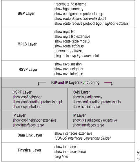
ソリューション
IPレイヤーとIGPレイヤーでは、以下のことを確認する必要があります。
-
インターフェイスには正しいIPアドレスが設定されており、IGPネイバーまたは隣接関係が確立されていること。
-
Open Shortest Path First(OSPF)またはIntermediate System-to-Intermediate System(IS-IS)プロトコルが正しく設定され、実行されていること。
-
OSPFプロトコルが設定されている場合は、最初にIPレイヤーをチェックし、次にOSPF設定をチェックし、プロトコル、インターフェイス、およびトラフィック制御が正しく設定されていることを確認します。
-
IS-ISプロトコルが設定されている場合、両方のプロトコルが互いに独立しているため、最初にIS-ISとIPのどちらをチェックするかは問題ではありません。IS-IS隣接関係が稼働していること、およびインターフェイスとIS-ISプロトコルが正しく設定されていることを確認します。
注:IS-ISプロトコルでは、トラフィック制御がデフォルトで有効になっています。
-
ネットワークがIPレイヤーまたはIGPレイヤーで機能していない場合、LSPは設定どおりに機能しません。
図8 は、このトピックで使用するMPLSネットワークを示しています。
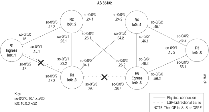 でネットワークが切断されたMPLS
図8に示すネットワークは、直接接続されているすべてのインターフェイスが、他のすべての類似したインターフェイスにパケットを受信および送信できる、完全にメッシュ化された構成です。このネットワークのLSPは、ingressルーターR1からトランジットルーターR3を経て、egressルーターR6に至るように設定されています。さらに、リバースLSPは、R6からR3を経てR1まで実行するように設定されており、双方向トラフィックを作成します。図8の十字は、IPおよびIGP層で次の問題が発生したためにLSPが機能していない場所を示しています。
-
ingressルーター(R1)でIPアドレスが正しく設定されていません。
-
OSPFプロトコルはルーターID(RID)で設定されていますが、ループバック(lo0)インターフェイスがなく、トラフィックエンジニアリングがトランジットルーター(R3)にありません。
-
IS-ISネットワークのレベルが一致していません。
IP レイヤーの検証
目的
IPレイヤーのチェックは、IGPとして設定されているかOSPFまたはIS-ISとして設定されているかによって、IGP(Interior Gateway Protocol)レイヤーのチェック前に行うことも、後に行うこともできます。MPLS ネットワークが OSPF を IGP として設定されている場合、まず IP レイヤーを検証し、インターフェイスに正しい IP アドレスが設定されていること、OSPF ネイバーが確立されていることを確認してから OSPF レイヤーを確認する必要があります。
MPLSネットワークでIGPとしてIS-ISが設定されている場合は、IPレイヤーまたはIS-ISプロトコルレイヤーのいずれかを先に確認できます。IP レイヤーまたは IS-IS レイヤーをチェックする順序は、結果に影響しません。
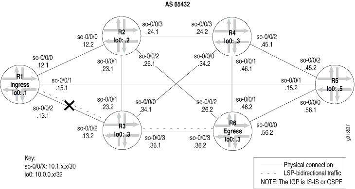 で切断されたネットワークMPLS
図9の十字は、ingressルーターR1のIPアドレスの設定が間違っているためにLSPが壊れている箇所を示しています。
LSP の検証
目的
LSPを設定した後、LSPが稼働していることを確認する必要があります。LSP には、ingress、トランジット、またはegressがあります。show mpls lspコマンドを使用して、LSPの状態を迅速に確認し、LSPがダウンした場合のフォローアップとして拡張オプション(show mpls lsp extensive) を使用します。ネットワークに多数のLSPがある場合、名前オプション(show mpls lsp namenameまたはshow mpls lsp name name extensive)を使用してLSPの名前を指定することを検討できます。
アクション
LSP が稼働していることを確認するには、ingressルーターから次のコマンドを入力します。
user@host> show mpls lsp extensive
サンプル出力 1
コマンド名
user@R1> show mpls lsp extensive
Ingress LSP: 1 sessions

10.0.0.6
  From: 10.0.0.1, State: Dn, ActiveRoute: 0, LSPname: R1-to-R6
   ActivePath: (none)
  LoadBalance: Random
  Encoding type: Packet, Switching type: Packet, GPID: IPv4
  Primary                    State: Dn
    Will be enqueued for recomputation in 25 second(s).
   44 Oct 15 16:56:11 CSPF failed:  no route toward 10.0.0.6 [2685 times]
   43 Oct 14 19:07:09 Clear Call
   42 Oct 14 19:06:56 Deselected as active
   41 Oct 14 19:06:56 10.1.12.1: MPLS label allocation failure
   40 Oct 14 19:06:56 Down
   39 Oct 14 18:43:43 Selected as active path
   38 Oct 14 18:43:43 Record Route:  10.1.13.2 10.1.36.2
   37 Oct 14 18:43:43 Up
   [...Output truncated...]
  Created: Thu Oct 14 16:04:33 2004
Total 1 displayed, Up 0,  Down 1

Egress LSP: 0 sessions
Total 0 displayed , Up 0, Down 0

Transit LSP: 0 sessions
Total 0 displayed , Up 0, Down 0
意味
ingressルーター R1 からの出力例では、MPLS ラベル割り当てに失敗し、CSPF(Constrained Shortest Path First)アルゴリズムが失敗した結果、R6 で宛先 10.0.0.6 へのルートがないことが示されています。
IPアドレッシングの検証
目的
IP レイヤーを調査する際には、インターフェイスに正しい IP アドレスが設定されていること、OSPF ネイバーまたは IS-IS 隣接関係が確立されていることを確認します。この例では、ingressルーター(R1)でIPアドレスが正しく設定されていません。
アクション
IPアドレッシングを確認するには、イングレス、トランジット、およびエグレスの各ルータから次のコマンドを入力します。
user@host> show interfaces terse
出力例
コマンド名
user@R1> show interfaces terse
Interface               Admin Link Proto Local                 Remote
so-0/0/0                up    up
so-0/0/0.0              up    up   inet  10.1.12.1/30
                                   iso
                                   mpls
so-0/0/1                up    up
so-0/0/1.0              up    up   inet  10.1.15.1/30
                                   iso
                                   mpls
so-0/0/2                up    up
so-0/0/2.0              up    up   inet  10.1.13.2 <<< Incorrect IP address
                                   iso
                                   mpls
lo0                     up    up
lo0.0                   up    up   inet  10.0.0.1
                                   iso   49.0004.1000.0000.0001.00

user@R3> show interfaces terse
Interface               Admin Link Proto Local                 Remote
so-0/0/0                up    up
so-0/0/0.0              up    up   inet  10.1.34.1/30
                                   iso
                                   mpls
so-0/0/1                up    up
so-0/0/1.0              up    up   inet  10.1.23.2/30
                                   iso
                                   mpls
so-0/0/2                up    up
so-0/0/2.0              up    up   inet  10.1.13.2/30 <<< Identical to R1
                                   iso
                                   mpls
so-0/0/3                up    up
so-0/0/3.0              up    up   inet  10.1.36.1/30
                                   iso
                                   mpls
lo0                     up    up
lo0.0                   up    up   inet  10.0.0.3
                                   iso   49.0004.1000.0000.0003.00

user@R6> show interfaces terse
Interface               Admin Link Proto Local                 Remote
so-0/0/0                up    up
so-0/0/0.0              up    up   inet  10.1.56.2/30
                                   iso
                                   mpls
so-0/0/1                up    up
so-0/0/1.0              up    up   inet  10.1.46.2/30
                                   iso
                                   mpls
so-0/0/2                up    up
so-0/0/2.0              up    up   inet  10.1.26.2/30
                                   iso
                                   mpls
so-0/0/3                up    up
so-0/0/3.0              up    up   inet  10.1.36.2/30
                                   iso
                                   mpls
lo0.0                   up    up   inet  10.0.0.6
                                   iso   49.0004.1000.0000.0006.00
意味
サンプル出力では、R1 のインターフェイス so-0/0/2.0 と R3 のインターフェイス so-0/0/2.0 の IP アドレスが同一であることを示しています。インターフェイスを正しく識別するためには、ネットワーク内のインターフェイスIPアドレスが一意である必要があります。
IP 層でのネイバーまたは隣接関係の検証
目的
IPアドレッシングが正しく設定されていない場合は、OSPFネイバーまたはIS-IS隣接関係の両方をチェックして、どちらか一方または両方が確立されているかどうかを判断する必要があります。
アクション
ネイバー(OSPF)または隣接関係(IS-IS)を検証するには、イングレス、トランジット、およびエグレスの各ルータから以下のコマンドを入力します。
user@host> show ospf neighbor extensive
user@host> show isis adjacency extensive
サンプル出力 1
コマンド名
user@R1> show ospf neighbor extensive
Address         Interface             State      ID              Pri  Dead
10.1.12.2        so-0/0/0.0             Full      10.0.0.2         128   34
  area 0.0.0.0, opt 0x42, DR 0.0.0.0, BDR 0.0.0.0
  Up 1d 04:45:20, adjacent 1d 04:45:20
10.1.15.2        so-0/0/1.0             Full      10.0.0.5         128   35
  area 0.0.0.0, opt 0x42, DR 0.0.0.0, BDR 0.0.0.0
  Up 1d 04:45:20, adjacent 1d 04:45:10  <<< no adjacency with R3 so-0/0/2

user@R3> show ospf neighbor extensive
Address         Interface             State      ID              Pri  Dead
10.1.23.1        so-0/0/1.0             Full      10.0.0.2         128   35
  area 0.0.0.0, opt 0x42, DR 0.0.0.0, BDR 0.0.0.0
  Up 1w2d 04:54:30, adjacent 1w2d 04:54:21
10.1.36.2        so-0/0/3.0             Full      10.0.0.6         128   39
  area 0.0.0.0, opt 0x42, DR 0.0.0.0, BDR 0.0.0.0
  Up 1w2d 04:54:30, adjacent 1w2d 04:54:30  <<< no adjacency with R1 so-0/0/2

user@R6> show ospf neighbor extensive
Address         Interface             State      ID              Pri  Dead
10.1.56.1        so-0/0/0.0             Full      10.0.0.5         128   39
  area 0.0.0.0, opt 0x42, DR 0.0.0.0, BDR 0.0.0.0
  Up 1d 02:59:35, adjacent 1d 02:59:35
10.1.26.1        so-0/0/2.0             Full      10.0.0.2         128   36
  area 0.0.0.0, opt 0x42, DR 0.0.0.0, BDR 0.0.0.0
  Up 1w2d 04:57:30, adjacent 1w2d 04:57:30
10.1.36.1        so-0/0/3.0             Full      10.0.0.3         128   36
  area 0.0.0.0, opt 0x42, DR 0.0.0.0, BDR 0.0.0.0
  Up 1w2d 04:56:11, adjacent 1w2d 04:56:11
サンプル出力2
コマンド名
user@R1> show isis adjacency extensive
R2
  Interface: so-0/0/0.0,  Level: 2, State: Up , Expires in 23 secs
  Priority: 0, Up/Down transitions: 1, Last transition: 05:57:16 ago
  Circuit type: 2,  Speaks: IP , IPv6
  Topologies: Unicast
  Restart capable: Yes
   IP addresses: 10.1.12.2
  Transition log:
  When                  State        Reason
  Fri Oct 15 14:58:35   Up           Seenself

R5
  Interface: so-0/0/1.0,  Level: 2, State: Up, Expires in 26 secs
  Priority: 0, Up/Down transitions: 1, Last transition: 05:56:52 ago
  Circuit type: 2,  Speaks: IP , IPv6
  Topologies: Unicast
  Restart capable: Yes
   IP addresses: 10.1.15.2
  Transition log:
  When                  State        Reason
  Fri Oct 15 14:59:00   Up           Seenself

R3
  Interface: so-0/0/2.0, Level: 2, State: Up, Expires in 26 secs
  Priority: 0, Up/Down transitions: 1, Last transition: 05:56:51 ago
  Circuit type: 2,  Speaks: IP , IPv6
  Topologies: Unicast
  Restart capable: Yes
  IP addresses: 10.1.13.2
  Transition log:
  When                  State        Reason
  Fri Oct 15 14:59:01   Up           Seenself

user@R3> show isis adjacency extensive
R4
  Interface: so-0/0/0.0,  Level: 2, State: Up , Expires in 25 secs
  Priority: 0, Up/Down transitions: 1, Last transition: 1w1d 00:22:51 ago
  Circuit type: 2,  Speaks: IP , IPv6
  Topologies: Unicast
  Restart capable: Yes
   IP addresses: 10.1.34.2
  Transition log:
  When                  State        Reason
  Thu Oct 28 15:13:12   Up           Seenself

R2
  Interface: so-0/0/1.0,  Level: 2, State: Up , Expires in 25 secs
  Priority: 0, Up/Down transitions: 1, Last transition: 2w2d 18:02:48 ago
  Circuit type: 2,  Speaks: IP , IPv6
  Topologies: Unicast
  Restart capable: Yes
   IP addresses: 10.1.23.1
  Transition log:
  When                  State        Reason
  Tue Oct 19 21:33:15   Up           Seenself

R1
  Interface: so-0/0/2.0,  Level: 2, State: Up , Expires in 22 secs
  Priority: 0, Up/Down transitions: 1, Last transition: 2w2d 17:24:06 ago
  Circuit type: 2,  Speaks: IP , IPv6
  Topologies: Unicast
  Restart capable: Yes
   IP addresses: 10.1.13.1
  Transition log:
  When                  State        Reason
  Tue Oct 19 22:11:57   Up           Seenself

R6
  Interface: so-0/0/3.0,  Level: 2, State: Up , Expires in 21 secs
  Priority: 0, Up/Down transitions: 1, Last transition: 2w1d 00:07:00 ago
  Circuit type: 2,  Speaks: IP , IPv6
  Topologies: Unicast
  Restart capable: Yes
   IP addresses: 10.1.36.2
  Transition log:
  When                  State        Reason
  Thu Oct 21 15:29:03   Up           Seenself

user@R6>  show isis adjacency extensive
R5
  Interface: so-0/0/0.0,  Level: 2, State: Up , Expires in 23 secs
  Priority: 0, Up/Down transitions: 1, Last transition: 1w2d 01:10:03 ago
  Circuit type: 2,  Speaks: IP , IPv6
  Topologies: Unicast
  Restart capable: Yes
   IP addresses: 10.1.56.1
  Transition log:
  When                  State        Reason
  Wed Oct 27 14:35:32   Up           Seenself

R4
  Interface: so-0/0/1.0,  Level: 2, State: Up , Expires in 25 secs
  Priority: 0, Up/Down transitions: 1, Last transition: 1w1d 00:26:50 ago
  Circuit type: 2,  Speaks: IP , IPv6
  Topologies: Unicast
  Restart capable: Yes
   IP addresses: 10.1.46.1
  Transition log:
  When                  State        Reason
  Thu Oct 28 15:18:45   Up           Seenself

R2
  Interface: so-0/0/2.0,  Level: 2, State: Up , Expires in 24 secs
  Priority: 0, Up/Down transitions: 1, Last transition: 2w1d 00:11:40 ago
  Circuit type: 2,  Speaks: IP , IPv6
  Topologies: Unicast
  Restart capable: Yes
   IP addresses: 10.1.26.1
  Transition log:
  When                  State        Reason
  Thu Oct 21 15:33:55   Up           Seenself

R3
  Interface: so-0/0/3.0,  Level: 2, State: Up , Expires in 19 secs
  Priority: 0, Up/Down transitions: 1, Last transition: 2w1d 00:11:40 ago
  Circuit type: 2,  Speaks: IP , IPv6
  Topologies: Unicast
  Restart capable: Yes
   IP addresses: 10.1.36.1
  Transition log:
  When                  State        Reason
  Thu Oct 21 15:33:55   Up           Seenself
意味
イングレス、トランジット、およびエグレスルーターからのサンプル出力1は、 R1 と R3 が確立されたOSPFネイバーではないことを示しています。2つのインターフェイス so-0/0/2.0 (R1 と R3)が同一のIPアドレスで設定されていることを考えると、これは予想されるでしょう。OSPFプロトコルは、IPパケットヘッダーに含まれる宛先IPアドレスのみに基づいてIPパケットをルーティングします。そのため、自律システム(AS)内で同一のIPアドレスがあると、ネイバーが確立されません。
イングレス、トランジット、およびイグレス ルーターからのサンプル出力 2 は、R1 と R3 のインターフェイス so-0/0/2.0 に設定された同じ IP アドレスにもかかわらず、R1 と R3 が IS-IS 隣接関係を確立していることを示しています。IS-ISプロトコルは、隣接関係を確立するためにIPに依存しないため、OSPFプロトコルとは異なる動作をします。ただし、LSP が起動していない場合でも、その層に間違いがある場合に備えて、IP サブネット アドレッシングを確認すると便利です。アドレス指定エラーを修正すると、LSP が復旧する場合があります。
適切なアクションを取る
問題点
説明
調査で発生したエラーに応じて、問題を修正するための適切なアクションを実行する必要があります。この例では、トランジット ルーター R2 のインターフェイスの IP アドレスが正しく設定されていません。
ソリューション
この例のエラーを修正するには、以下のコマンドを入力します。
[edit interfaces                            so-0/0/2]
user@R1# show
user@R1#              rename unit 0 family inet address 10.1.13.2/30 to address              10.1.13.1/30
user@R1# show
user@R1# commit
出力例
[edit interfaces so-0/0/2]
user@R1# show
unit 0 {
    family inet {
        address 10.1.13.2/30;  <<< Incorrect IP address
    }
    family iso;
    family mpls;
}

[edit interfaces so-0/0/2]
user@R1# rename unit 0 family inet address 10.1.13.2/30 to address 10.1.13.1/30

[edit interfaces so-0/0/2]
user@R1# show
unit 0 {
    family inet {
        address 10.1.13.1/30;  <<< Correct IP address.
    }
    family iso;
    family mpls;
}

[edit interfaces so-0/0/2]
user@R1# commit
commit complete
意味
サンプル出力は、ingressルーターR1のインターフェイスso-0/0/2が正しいIPアドレスで設定されていることを示しています。この修正により、IPレイヤーとIGPレイヤーで切断されたMPLSネットワークのMPLSネットワーク内のすべてのインターフェイスに一意のサブネットIPアドレスが与えられ、LSPが立ち上がる可能性が生じます。
LSP の再検証
目的
エラーを修正するために適切な処置を行った後、LSP を再度チェックして、OSPF プロトコルの問題が解決されたことを確認する必要があります。
アクション
LSPを再度確認するには、イングレス、トランジット、およびエグレスルーターで次のコマンドを入力します。
user@host> show mpls lsp extensive
サンプル出力 1
コマンド名
user@R1> show mpls lsp extensive
Ingress LSP: 1 sessions

10.0.0.6
  From: 10.0.0.1, State: Up,  ActiveRoute: 1 , LSPname: R1-to-R6
  ActivePath:  (primary)
  LoadBalance: Random
  Encoding type: Packet, Switching type: Packet, GPID: IPv4
 *Primary                     State: Up
    Computed ERO (S [L] denotes strict [loose] hops): (CSPF metric: 20)
 10.1.13.2 S 10.1.36.2 S
    Received RRO (ProtectionFlag 1=Available 2=InUse 4=B/W 8=Node 10=SoftPreempt):
          10.1.13.2 10.1.36.2
   54 Oct 15 21:28:16 Selected as active path
   53 Oct 15 21:28:16 Record Route:  10.1.13.2 10.1.36.2
   52 Oct 15 21:28:16 Up
   51 Oct 15 21:28:16 10.1.15.1: MPLS label allocation failure[2 times]
   50 Oct 15 21:28:11 CSPF: computation result accepted
   49 Oct 15 21:27:42 10.1.15.1: MPLS label allocation failure
   48 Oct 15 21:27:42 CSPF: computation result accepted
   47 Oct 15 21:27:31 10.1.15.1: MPLS label allocation failure[4 times]
   46 Oct 15 21:27:13 Originate Call
   45 Oct 15 21:27:13 CSPF: computation result accepted
   [...Output truncated...]
  Created: Thu Oct 14 16:04:34 2004
Total 1 displayed,  Up 1 , Down 0

Egress LSP: 1 sessions

10.0.0.1
  From: 10.0.0.6,  LSPstate: Up , ActiveRoute: 0
   LSPname: R6-to-R1 , LSPpath: Primary
  Suggested label received: -, Suggested label sent: -
   Recovery label received: -, Recovery label sent: -
  Resv style: 1 FF, Label in: 3, Label out: -
  Time left:  149, Since: Fri Oct 15 21:28:13 2004
  Tspec: rate 0bps size 0bps peak Infbps m 20 M 1500
  Port number: sender 13 receiver 39024 protocol 0
  PATH rcvfrom: 10.1.13.2 (so-0/0/2.0) 10 pkts
  Adspec: received MTU 1500
  PATH sentto: localclient
  RESV rcvfrom: localclient
   Record route: 10.1.36.2 10.1.13.2 <self>
Total 1 displayed,  Up 1 , Down 0

Transit LSP: 0 sessions
Total 0 displayed, Up 0, Down 0
サンプル出力2
コマンド名
user@R3> show mpls lsp extensive
Ingress LSP: 0 sessions
Total 0 displayed, Up 0, Down 0

Egress LSP: 0 sessions
Total 0 displayed, Up 0, Down 0

Transit LSP: 2 sessions

10.0.0.1
  From: 10.0.0.6,  LSPstate: Up , ActiveRoute: 1
   LSPname: R6-to-R1 , LSPpath: Primary
  Suggested label received: -, Suggested label sent: -
  Recovery label received: -, Recovery label sent: 3
  Resv style: 1 FF, Label in: 100336, Label out: 3
  Time left:  156, Since: Fri Oct 15 21:15:47 2004
  Tspec: rate 0bps size 0bps peak Infbps m 20 M 1500
  Port number: sender 13 receiver 39024 protocol 0
  PATH rcvfrom: 10.1.36.2 (so-0/0/3.0) 11 pkts
  Adspec: received MTU 1500 sent MTU 1500
  PATH sentto: 10.1.13.1 (so-0/0/2.0) 11 pkts
  RESV rcvfrom: 10.1.13.1 (so-0/0/2.0) 11 pkts
  Explct route: 10.1.13.1
   Record route: 10.1.36.2 <self> 10.1.13.1

10.0.0.6
  From: 10.0.0.1,  LSPstate: Up , ActiveRoute: 1
   LSPname: R1-to-R6 , LSPpath: Primary
  Suggested label received: -, Suggested label sent: -
  Recovery label received: -, Recovery label sent: 3
  Resv style: 1 FF, Label in: 100352, Label out: 3
  Time left:  159, Since: Fri Oct 15 21:15:50 2004
  Tspec: rate 0bps size 0bps peak Infbps m 20 M 1500
  Port number: sender 5 receiver 47901 protocol 0
  PATH rcvfrom: 10.1.13.1 (so-0/0/2.0) 11 pkts
  Adspec: received MTU 1500 sent MTU 1500
  PATH sentto: 10.1.36.2 (so-0/0/3.0) 11 pkts
  RESV rcvfrom: 10.1.36.2 (so-0/0/3.0) 11 pkts
  Explct route: 10.1.36.2
   Record route: 10.1.13.1 <self> 10.1.36.2
Total 2 displayed,  Up 2 , Down 0
サンプル出力 3
コマンド名
user@R6> show mpls lsp extensive
Ingress LSP: 1 sessions

10.0.0.1
  From: 10.0.0.6,  State: Up , ActiveRoute: 1,  LSPname: R6-to-R1
  ActivePath:  (primary)
  LoadBalance: Random
  Encoding type: Packet, Switching type: Packet, GPID: IPv4
 *Primary                    State: Up
    Computed ERO (S [L] denotes strict [loose] hops): (CSPF metric: 20)
 10.1.36.1 S 10.1.13.1 S
    Received RRO (ProtectionFlag 1=Available 2=InUse 4=B/W 8=Node 10=SoftPreempt):
          10.1.36.1 10.1.13.1
   187 Oct 15 21:20:05 Selected as active path
   186 Oct 15 21:20:05 Record Route:  10.1.36.1 10.1.13.1
   185 Oct 15 21:20:05 Up
   184 Oct 15 21:20:05 Clear Call
   183 Oct 15 21:20:05 CSPF: computation result accepted
   182 Oct 15 21:20:05 CSPF: link down/deleted 10.1.13.2(R3.00/10.0.0.3)->10.1.13.2(R1.00/10.0.0.1)
   [...Output truncated...]
  Created: Tue Aug 17 12:18:33 2004
Total 1 displayed,  Up 1 , Down 0

Egress LSP: 1 sessions

10.0.0.6
  From: 10.0.0.1, LSPstate: Up, ActiveRoute: 0
   LSPname: R1-to-R6 , LSPpath: Primary
  Suggested label received: -, Suggested label sent: -
  Recovery label received: -, Recovery label sent: -
  Resv style: 1 FF, Label in: 3, Label out: -
  Time left:  144, Since: Fri Oct 15 21:20:08 2004
  Tspec: rate 0bps size 0bps peak Infbps m 20 M 1500
  Port number: sender 5 receiver 47901 protocol 0
  PATH rcvfrom: 10.1.36.1 (so-0/0/3.0) 11 pkts
  Adspec: received MTU 1500
  PATH sentto: localclient
  RESV rcvfrom: localclient
   Record route: 10.1.13.1 10.1.36.1 <self>
Total 1 displayed,  Up 1 , Down 0

Transit LSP: 0 sessions
Total 0 displayed, Up 0, Down 0
意味
ingress ルーターR1 からのサンプル出力1は、LSP R1-to-R6 に R6 へのアクティブなルートがあり、状態がupであることを示しています。出力は、エグレスLSPセッション R6-to-R1 が回復ラベルを受信し、送信したことを示しています。
トランジット ルーター R3 からのサンプル出力 2 では、 R1 から R6 と R6 から R1 の 2 つのトランジット LSP セッションが存在することがわかります 。 両方のLSPが立ち上がっています。
egress ルーターR6 からのサンプル出力3は、LSPが稼働しており、アクティブなルートがプライマリルートであることを示しています。LSP はこれで、 R1 から R3 から R6 までの予想通りのパスに沿ってネットワークを通過し、リバース LSP は R6 から R3 から R1 へとネットワークを通過しています。
LSP の再検証
目的
エラーを修正するために適切な処置を行った後、LSP を再度チェックして、IS-IS プロトコルの問題が解決されたことを確認する必要があります。
アクション
LSP がアップしており、想定通りにネットワークを通過していることを確認するには、イングレス、エグレス、トランジットの各ルータから次のコマンドを入力します。
user@host> show mpls lsp extensive
出力例
コマンド名
user@R1> show mpls lsp extensive
Ingress LSP: 1 sessions

10.0.0.6
  From: 10.0.0.1,  State: Up , ActiveRoute: 1,  LSPname: R1-to-R6
   ActivePath:  (primary)
  LoadBalance: Random
  Encoding type: Packet, Switching type: Packet, GPID: IPv4
 *Primary                    State: Up
    Received RRO (ProtectionFlag 1=Available 2=InUse 4=B/W 8=Node 10=SoftPreempt):
          10.1.13.2 10.1.36.2
    4 Oct 19 21:22:54 Selected as active path
    3 Oct 19 21:22:53 Record Route:  10.1.13.2 10.1.36.2
    2 Oct 19 21:22:53 Up
    1 Oct 19 21:22:53 Originate Call
  Created: Tue Oct 19 21:22:53 2004
Total 1 displayed,  Up 1 , Down 0

Egress LSP: 1 sessions

10.0.0.1
  From: 10.0.0.6,  LSPstate: Up , ActiveRoute: 0
   LSPname: R6-to-R1 , LSPpath: Primary
  Suggested label received: -, Suggested label sent: -
  Recovery label received: -, Recovery label sent: -
  Resv style: 1 FF, Label in: 3, Label out: -
  Time left:  117, Since: Tue Oct 19 21:17:42 2004
  Tspec: rate 0bps size 0bps peak Infbps m 20 M 1500
  Port number: sender 2 receiver 39064 protocol 0
  PATH rcvfrom: 10.1.13.2 (so-0/0/2.0) 10 pkts
  Adspec: received MTU 1500
  PATH sentto: localclient
  RESV rcvfrom: localclient
  Record route: 10.1.36.2 10.1.13.2 <self>
Total 1 displayed,  Up 1 , Down 0

Transit LSP: 0 sessions
Total 0 displayed, Up 0, Down 0

user@R3> show mpls lsp extensive
Ingress LSP: 0 sessions
Total 0 displayed, Up 0, Down 0

Egress LSP: 0 sessions
Total 0 displayed, Up 0, Down 0

Transit LSP:  2 sessions

10.0.0.1
  From: 10.0.0.6, LSPstate: Up, ActiveRoute: 1
   LSPname: R6-to-R1 , LSPpath: Primary
  Suggested label received: -, Suggested label sent: -
  Recovery label received: -, Recovery label sent: 3
  Resv style: 1 FF, Label in: 100416, Label out: 3
  Time left:  139, Since: Tue Oct 19 21:05:11 2004
  Tspec: rate 0bps size 0bps peak Infbps m 20 M 1500
  Port number: sender 2 receiver 39064 protocol 0
  PATH rcvfrom: 10.1.36.2 (so-0/0/3.0) 11 pkts
  Adspec: received MTU 1500 sent MTU 1500
  PATH sentto: 10.1.13.1 (so-0/0/2.0) 11 pkts
  RESV rcvfrom: 10.1.13.1 (so-0/0/2.0) 11 pkts
  Explct route: 10.1.13.1
  Record route: 10.1.36.2 <self> 10.1.13.1

10.0.0.6
  From: 10.0.0.1, LSPstate: Up, ActiveRoute: 1
   LSPname: R1-to-R6 , LSPpath: Primary
  Suggested label received: -, Suggested label sent: -
  Recovery label received: -, Recovery label sent: 3
  Resv style: 1 FF, Label in: 100448, Label out: 3
  Time left:  135, Since: Tue Oct 19 21:10:22 2004
  Tspec: rate 0bps size 0bps peak Infbps m 20 M 1500
  Port number: sender 1 receiver 47951 protocol 0
  PATH rcvfrom: 10.1.13.1 (so-0/0/2.0) 4 pkts
  Adspec: received MTU 1500 sent MTU 1500
  PATH sentto: 10.1.36.2 (so-0/0/3.0) 4 pkts
  RESV rcvfrom: 10.1.36.2 (so-0/0/3.0) 4 pkts
  Record route: 10.1.13.1 <self> 10.1.36.2
Total 2 displayed,  Up 2 , Down 0

user@R6>  run show mpls lsp extensive
Ingress LSP: 1 sessions

10.0.0.1
  From: 10.0.0.6, State: Up, ActiveRoute: 1, LSPname: R6-to-R1
  ActivePath:  (primary)
  LoadBalance: Random
  Encoding type: Packet, Switching type: Packet, GPID: IPv4
 *Primary                    State: Up
    Computed ERO (S [L] denotes strict [loose] hops): (CSPF metric: 2)
 10.1.36.1 S 10.1.13.1 S
    Received RRO (ProtectionFlag 1=Available 2=InUse 4=B/W 8=Node 10=SoftPreempt):
          10.1.36.1 10.1.13.1
   19 Oct 19 21:09:52 Selected as active path
   18 Oct 19 21:09:52 Record Route:  10.1.36.1 10.1.13.1
   17 Oct 19 21:09:52 Up
   16 Oct 19 21:09:52 Originate Call
   15 Oct 19 21:09:52 CSPF: computation result accepted
  Created: Tue Oct 19 18:30:09 2004
Total 1 displayed,  Up 1 , Down 0

Egress LSP: 1 sessions

10.0.0.6
  From: 10.0.0.1, LSPstate: Up, ActiveRoute: 0
   LSPname: R1-to-R6 , LSPpath: Primary
  Suggested label received: -, Suggested label sent: -
  Recovery label received: -, Recovery label sent: -
  Resv style: 1 FF, Label in: 3, Label out: -
  Time left:  120, Since: Tue Oct 19 21:15:03 2004
  Tspec: rate 0bps size 0bps peak Infbps m 20 M 1500
  Port number: sender 1 receiver 47951 protocol 0
  PATH rcvfrom: 10.1.36.1 (so-0/0/3.0) 4 pkts
  Adspec: received MTU 1500
  PATH sentto: localclient
  RESV rcvfrom: localclient
  Record route: 10.1.13.1 10.1.36.1 <self>
Total 1 displayed,  Up 1 , Down 0

Transit LSP: 0 sessions
Total 0 displayed, Up 0, Down 0
意味
ingressルーター R1 と egressルーター R6 からの出力例は、LSP が R1 から R3 から R6 までの予想通りのパスに沿ってネットワークを通過していることを示しており、逆 LSP は R6 から R3 から R1 へと移動していることを示しています。さらに、トランジット ルーター R3 からのサンプル出力は、 R1 から R6 への 1 つと、 R6 から R1 への 2 つのトランジット LSP セッションが存在することを示しています。
RSVP 層の確認
目的
ラベルスイッチパス(LSP)を設定し、 show mpls lsp extensive コマンドを発行し、エラーがあると判断した後、エラーが物理層、データリンク層、またはインターネットプロトコル(IP)層と内部ゲートウェイプロトコル(IGP層)にないことが分かる場合があります。引き続き、ネットワークの RSVP 層で問題を調査します。
図10 は、階層化MPLSモデルのRSVP層を示しています。
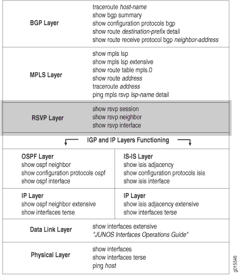 の確認
の確認
この層では、動的 RSVP シグナリングが予想通りに発生し、ネイバーが接続され、インターフェイスが RSVP 用に正しく設定されていることを確認します。イングレス、エグレス、およびトランジット ルーターを確認します。
ネットワークがこの層で機能していない場合、LSP は設定どおりに機能しません。
図11 は、このトピックで使用するMPLSネットワークを示しています。
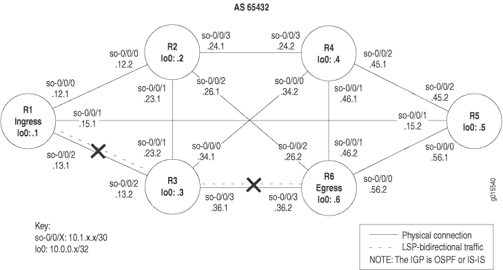 で切断されたMPLSネットワーク
図11に示すネットワークは、直接接続されているすべてのインターフェイスが、他のすべての類似したインターフェイスにパケットを受信および送信できる、完全にメッシュ化された設定です。このネットワークのLSPは、ingressルーターR1からトランジットルーターR3を経て、egressルーターR6に至るように設定されています。さらに、リバースLSPは、R6からR3からR1まで実行するように設定されており、双方向トラフィックを作成します。
しかし、この例では、 R1 から R6 、 または R6 から R1 のどの方向にもパスがなく LSP がダウンしています。
図11に示す十字は、LSPが壊れている箇所を示しています。LSP が壊れている理由としては、動的 RSVP シグナリングが予想通りに発生していない、ネイバーが接続されていない、またはインターフェイスが RSVP 用に正しく設定されていないといった理由が考えられます。
図 11 のネットワークでは、トランジット ルーター R3 の設定エラーにより、LSP が予想通りにネットワークを通過することができません。
RSVP 層を確認するには、次の手順に従います。
LSP の検証
目的
通常、LSPの検証にはshow mpls lsp extensive コマンドを使用します。ただし、LSP の状態を迅速に確認するには、show mpls lsp コマンドを使用します。LSP がダウンしている場合は、フォローアップとして拡張オプション(show mpls lsp extensive) を使用します。ネットワークに多数のLSPがある場合、名前オプション(show mpls lsp name nameまたはshow mpls lsp namename extensive)を使用して、LSPの名前を指定することを検討できます。
アクション
LSP が稼働しているかどうかを確認するには、ingressルーターから次のコマンドを入力します。
user@host> show mpls lsp extensive
サンプル出力 1
コマンド名
user@R1> show mpls lsp extensive
Ingress LSP: 1 sessions

10.0.0.6
  From: 10.0.0.1, State: Dn, ActiveRoute: 0,  LSPname: R1-to-R6
  ActivePath: (none)
  LoadBalance: Random
  Encoding type: Packet, Switching type: Packet, GPID: IPv4
  Primary                    State: Dn
    2 Oct 27 15:06:05 10.1.13.2:  No Route toward dest [4 times]
    1 Oct 27 15:05:56 Originate Call
  Created: Wed Oct 27 15:05:55 2004
Total 1 displayed, Up 0,  Down 1

Egress LSP: 0 sessions
Total 0 displayed, Up 0, Down 0

Transit LSP: 0 sessions
Total 0 displayed, Up 0, Down 0

user@R3> show mpls lsp extensive
Ingress LSP: 0 sessions
Total 0 displayed, Up 0, Down 0

Egress LSP: 0 sessions
Total 0 displayed, Up 0, Down 0

Transit LSP: 0 sessions
Total 0 displayed, Up 0, Down 0

user@R6> show mpls lsp extensive
Ingress LSP: 1 sessions

10.0.0.1
  From: 10.0.0.6, State: Dn, ActiveRoute: 0,  LSPname: R6-to-R1
  ActivePath: (none)
  LoadBalance: Random
  Encoding type: Packet, Switching type: Packet, GPID: IPv4
  Primary                    State: Dn
    Will be enqueued for recomputation in 22 second(s).
    1 Oct 27 14:59:12  CSPF failed: no route toward 10.0.0.1 [4 times]
  Created: Wed Oct 27 14:57:44 2004
Total 1 displayed, Up 0,  Down 1

Egress LSP: 0 sessions
Total 0 displayed, Up 0, Down 0

Transit LSP: 0 sessions
Total 0 displayed, Up 0, Down 0
意味
サンプル出力では、 LSP が R1 から R6 と R6 から R1 の両方向にダウンしていることが示されています。 R1 からの出力は、 R1 が宛先に到達できずに通話を発信しようとしたため、cspf なしのLSPを使用していることを示しています。 R6 からの出力は、CSPF(制約付き最短パスファースト)アルゴリズムが失敗したため、宛先 10.0.0.1へのルートが得られなかったことを示しています。
RSVP セッションの検証
目的
RSVP セッションの作成に成功すると、RSVP セッションで作成されたパスに沿って LSP が設定されます。RSVP セッションが失敗すると、LSP は設定どおりに機能しません。
アクション
現在アクティブなRSVPセッションを確認するには、イングレス、トランジット、およびエグレスの各ルータから次のコマンドを入力します。
user@host> show rsvp session
サンプル出力 1
コマンド名
user@R1> show rsvp session
Ingress RSVP: 0 sessions
Total 0 displayed, Up 0, Down 0

Egress RSVP: 0 sessions
Total 0 displayed, Up 0, Down 0

Transit RSVP: 0 sessions
Total 0 displayed, Up 0, Down 0

user@R3> show rsvp session
Ingress RSVP: 0 sessions
Total 0 displayed, Up 0, Down 0

Egress RSVP: 0 sessions
Total 0 displayed, Up 0, Down 0

Transit RSVP: 0 sessions
Total 0 displayed, Up 0, Down 0

user@R6> show rsvp session
Ingress RSVP: 0 sessions
Total 0 displayed, Up 0, Down 0

Egress RSVP: 0 sessions
Total 0 displayed, Up 0, Down 0

Transit RSVP: 0 sessions
Total 0 displayed, Up 0, Down 0
サンプル出力2
コマンド名
user@R1> show rsvp session
Ingress RSVP: 1 sessions
To              From            State Rt Style Labelin Labelout LSPname
10.0.0.6        10.0.0.1        Up     1 1 FF       -   100768  R1-to-R6
Total 1 displayed,  Up 1 , Down 0

Egress RSVP: 1 sessions
To              From            State Rt Style Labelin Labelout LSPname
10.0.0.1        10.0.0.6        Up     0 1 FF       3        -  R6-to-R1
Total 1 displayed,  Up 1 , Down 0

Transit RSVP: 0 sessions
Total 0 displayed, Up 0, Down 0

user@R3> show rsvp session
Ingress RSVP: 0 sessions
Total 0 displayed, Up 0, Down 0

Egress RSVP: 0 sessions
Total 0 displayed, Up 0, Down 0

Transit RSVP:  2 sessions
To              From            State Rt Style Labelin Labelout LSPname
10.0.0.1        10.0.0.6        Up     1 1 FF  100784        3  R6-to-R1
10.0.0.6        10.0.0.1        Up     1 1 FF  100768        3  R1-to-R6
Total 2 displayed,  Up 2 , Down 0

user@R6> show rsvp session
Ingress RSVP: 1 sessions
To              From            State Rt Style Labelin Labelout LSPname
10.0.0.1        10.0.0.6        Up     1 1 FF       -   100784  R6-to-R1
Total 1 displayed,  Up 1 , Down 0

Egress RSVP: 1 sessions
To              From            State Rt Style Labelin Labelout LSPname
10.0.0.6        10.0.0.1        Up     0 1 FF       3        -  R1-to-R6
Total 1 displayed,  Up 1 , Down 0

Transit RSVP: 0 sessions
Total 0 displayed, Up 0, Down 0
意味
すべてのルーターからのサンプル出力 1 では、LSP R6-to-R1 が設定されていても、RSVP セッションは正常に作成されませんでした。
サンプル出力 1 とは対照的に、正しい出力を説明するために、サンプル出力 2 は、RSVP 設定が正しく、LSP が設定どおりにネットワークを通過している場合のイングレス、トランジット、およびエグレス ルーターからの出力を示しています。 R1 と R6 はどちらも、LSP R1からR6、および逆LSP R6からR1で、イングレスとエグレスのRSVPセッションを示しています。トランジット ルーター R3 は、2 つのトランジット RSVP セッションを示しています。
RSVPネイバーの検証
目的
RSVPパケットの交換時に動的に学習されたRSVPネイバーのリストを表示します。ネイバーが学習されると、RSVP 設定がルーターから削除されない限り、RSVP ネイバーのリストから削除されることはありません。
アクション
RSVP ネイバーを確認するには、イングレス、トランジット、およびエグレス ルーターから次のコマンドを入力します。
user@host> show rsvp neighbor
サンプル出力 1
コマンド名
user@R1> show rsvp neighbor
RSVP neighbor: 1 learned
Address            Idle Up/Dn LastChange HelloInt HelloTx/Rx MsgRcvd
10.1.13.2            10   1/0         9:22        9    64/64   32

user@R3> show rsvp neighbor
RSVP neighbor: 2 learned
Address            Idle Up/Dn LastChange HelloInt HelloTx/Rx MsgRcvd
10.1.13.1             0  1/0       28:20        9   190/190  41
10.1.36.2         16:50   1/1        15:37        9   105/78   38

user@R6> show rsvp neighbor
RSVP neighbor: 1 learned
Address            Idle Up/Dn LastChange HelloInt HelloTx/Rx MsgRcvd
10.1.36.1         17:30   1/1        16:15        9   104/78   39
サンプル出力2
コマンド名
user@R3> show rsvp neighbor
RSVP neighbor: 2 learned
Address            Idle Up/Dn LastChange HelloInt HelloTx/Rx MsgRcvd
10.1.13.1             5   1/0         9:14        9    63/63   33
10.1.36.2             5   1/0         9:05        9    62/62   32

user@R6> show rsvp neighbor
RSVP neighbor: 1 learned
Address            Idle Up/Dn LastChange HelloInt HelloTx/Rx MsgRcvd
10.1.36.1             5   1/0        8:54        9    61/61   32
意味
サンプル出力 1 は、R1 と R6 にそれぞれ 1 つの RSVP ネイバー、R3 があることを示しています。ただし、Up/Dnフィールドの値は異なります。R1の値は1/0、R6の値は1/1であり、これはR1がR3とのアクティブなネイバーであるが、R6はそうではないことを示しています。アップカウントがダウンカウントより1つ多い場合、ネイバーはアクティブです。値が等しい場合、ネイバーはダウンしています。R6の値は等しくて1/1で、ネイバーR3がダウンしていることを示しています。
トランジット ルーター R3 は、 R1 と R6 の 2 つのネイバーについて認識しています。 Up/Dn フィールドは、 R1 がアクティブなネイバーで、 R6 がダウンしていることを示しています。この時点では、両方のネイバーがアクティブではないため、問題が R3 にあるのか R6にあるのかを判断することはできません。
サンプル出力1とは対照的に、正しい出力を説明するために、サンプル出力2はトランジット ルーターR3 とegress ルーターR6の間の正しいネイバー関係を示しています。 Up/Dn フィールドには、アップカウントがダウンカウントの 1/0より1つ多く表示されており、ネイバーがアクティブであることを示しています。
RSVPインターフェイスの検証
目的
設定エラーが発生した場所を特定するために、RSVP が有効になっている各インターフェイスのステータスを表示します。
アクション
RSVP インターフェイスのステータスを確認するには、イングレス、トランジット、およびエグレスの各ルータから次のコマンドを入力します。
user@host> show rsvp interface
サンプル出力 1
コマンド名
user@R1> show rsvp interface
RSVP interface: 3 active
                   Active  Subscr- Static      Available   Reserved    Highwater
Interface   State  resv   iption  BW          BW          BW          mark
so-0/0/0.0  Up         0   100%  155.52Mbps  155.52Mbps  0bps        0bps
so-0/0/1.0  Up         0   100%  155.52Mbps  155.52Mbps  0bps        0bps
so-0/0/2.0  Up          0    100%  155.52Mbps  155.52Mbps  0bps        0bps

user@R3> show rsvp interface
RSVP interface: 3 active
                   Active  Subscr- Static      Available   Reserved    Highwater
Interface   State  resv    iption  BW          BW          BW          mark
so-0/0/0.0  Up         0   100%  155.52Mbps  155.52Mbps  0bps        0bps
so-0/0/1.0  Up         0   100%  155.52Mbps  155.52Mbps  0bps        0bps
so-0/0/2.0  Up          0    100%  155.52Mbps  155.52Mbps  0bps        0bps
<<< Missing interface so-0/0/3.0

user@R6> show rsvp interface
RSVP interface: 4 active
                   Active  Subscr- Static      Available   Reserved    Highwater
Interface   State  resv    iption  BW          BW          BW          mark
so-0/0/0.0  Up         0   100%  155.52Mbps  155.52Mbps  0bps        0bps
so-0/0/1.0  Up         0   100%  155.52Mbps  155.52Mbps  0bps        0bps
so-0/0/2.0  Up         0   100%  155.52Mbps  155.52Mbps  0bps        0bps
so-0/0/3.0  Up          0    100%  155.52Mbps  155.52Mbps  0bps        0bps
サンプル出力2
コマンド名
user@R1> show rsvp interface
RSVP interface: 3 active
                  Active Subscr- Static      Available   Reserved    Highwater
Interface   State resv   iption  BW          BW          BW          mark
so-0/0/0.0  Up         0   100%  155.52Mbps  155.52Mbps  0bps        0bps
so-0/0/1.0  Up         0   100%  155.52Mbps  155.52Mbps  0bps        0bps
so-0/0/2.0  Up          1    100%  155.52Mbps  155.52Mbps  0bps        0bps

user@R3> show rsvp interface
RSVP interface: 4 active
                  Active Subscr- Static      Available   Reserved    Highwater
Interface   State resv   iption  BW          BW          BW          mark
so-0/0/0.0  Up         0   100%  155.52Mbps  155.52Mbps  0bps        0bps
so-0/0/1.0  Up         0   100%  155.52Mbps  155.52Mbps  0bps        0bps
so-0/0/2.0  Up          1    100%  155.52Mbps  155.52Mbps  0bps        0bps
so-0/0/3.0  Up          1    100%  155.52Mbps  155.52Mbps  0bps        0bps

user@R6> show rsvp interface
RSVP interface: 4 active
                  Active Subscr- Static      Available   Reserved    Highwater
Interface   State resv   iption  BW          BW          BW          mark
so-0/0/0.0  Up         0   100%  155.52Mbps  155.52Mbps  0bps        0bps
so-0/0/1.0  Up         0   100%  155.52Mbps  155.52Mbps  0bps        0bps
so-0/0/2.0  Up         0   100%  155.52Mbps  155.52Mbps  0bps        0bps
so-0/0/3.0  Up          1    100%  155.52Mbps  155.52Mbps  0bps        0bps
意味
サンプル出力 1 では、各ルーターに稼働していて RSVP がアクティブなインターフェイスがあっても、どのルーターにも予約(アクティブ resv) がないことがわかります。この例では、イングレスルーターとエグレスルーターに少なくとも1つの予約があり、トランジットルーターに2つの予約があることが想定されます。
また、トランジットルーターR3のインターフェイスso-0/0/3は設定に含まれていません。このインターフェイスを含めることは、LSP の成功に不可欠です。
サンプル出力 1 とは対照的に、正しい出力を示すために、サンプル出力 2 はアクティブな予約を持つ関連インターフェイスを示しています。
RSVP プロトコル設定の検証
目的
RSVP セッション、インターフェイス、ネイバーを確認し、設定エラーがある可能性があると判断した後、RSVP プロトコルの設定を確認します。
アクション
RSVP の設定を確認するには、イングレス、トランジット、およびエグレスの各ルータから次のコマンドを入力します。
user@host> show configuration protocols rsvp
出力例
コマンド名
user@R1> show configuration protocols rsvp
interface so-0/0/0.0;
interface so-0/0/1.0;
interface so-0/0/2.0;
interface fxp0.0 {
    disable;
}

user@R3> show configuration protocols rsvp
interface so-0/0/0.0;
interface so-0/0/1.0;
interface so-0/0/2.0; <<< Missing interface so-0/0/3.0
interface fxp0.0 {
    disable;
}

user@R6> show configuration protocols rsvp
interface so-0/0/0.0;
interface so-0/0/1.0;
interface so-0/0/2.0;
interface so-0/0/3.0;
interface fxp0.0 {
    disable;
}
意味
サンプル出力は、 R3 のRSVPプロトコル設定にインターフェイス so-0/0/3.0 がないことを示しています。このインターフェイスは、LSP が正しく機能するために重要です。
適切なアクションを取る
問題点
説明
調査で発生したエラーに応じて、問題を修正するための適切なアクションを実行する必要があります。この例では、ルーター R3 の設定にインターフェイスがありません。
ソリューション
この例のエラーを修正するには、次の手順に従います。
-
トランジット ルーター R3 の設定に欠落しているインターフェイスを含めます。
user@R3> edit
user@R3#                   edit protocols rsvp
[edit protocols rsvp]
user@R3# show
user@R3#                   set interface so-0/0/3.0
-
設定を確認し、コミットします。
[edit protocols rsvp]
user@R3# show
user@R3# commit
出力例
user@R3> edit
Entering configuration mode

[edit]
user@R3# edit protocols rsvp

[edit protocols rsvp]
user@R3# show
interface so-0/0/0.0;
interface so-0/0/1.0;
interface so-0/0/2.0; <<< Missing interface so-0/0/3.0
interface fxp0.0 {
    disable;
}
[edit protocols rsvp]
user@R3# set interface so-0/0/3.0

[edit protocols rsvp]
user@R3# show
interface so-0/0/0.0;
interface so-0/0/1.0;
interface so-0/0/2.0;
interface fxp0.0 {
    disable;
}
interface so-0/0/3.0; <<< Interface now included in the configuration

[edit protocols rsvp]
user@R3# commit
commit complete
意味
サンプル出力は、トランジット ルーター R3 で欠落しているインターフェイス so-0/0/3.0 が [edit protocols rsvp] 階層レベルで正しく含まれるようになったことを示しています。これにより、LSPが立ち上がる可能性があります。
LSP の再検証
目的
エラーを修正するために適切な処置を行った後、LSP を再度チェックして、MPLS 層の問題が解決されたことを確認する必要があります。
アクション
LSPを再度確認するには、イングレス、トランジット、およびエグレスルーターで次のコマンドを入力します。
user@host> show mpls lsp extensive
サンプル出力 1
コマンド名
user@R1> show mpls lsp extensive
Ingress LSP: 1 sessions

10.0.0.6
  From: 10.0.0.1, State: Up,  ActiveRoute: 1 ,  LSPname: R1-to-R6
  ActivePath:  (primary)
  LoadBalance: Random
  Encoding type: Packet, Switching type: Packet, GPID: IPv4
 *Primary                    State: Up
    Received RRO (ProtectionFlag 1=Available 2=InUse 4=B/W 8=Node 10=SoftPreempt):
          10.1.13.2 10.1.36.2
    5 Oct 27 15:28:57 Selected as active path
    4 Oct 27 15:28:57  Record Route:  10.1.13.2 10.1.36.2
    3 Oct 27 15:28:57 Up
    2 Oct 27 15:28:44 10.1.13.2: No Route toward dest[35 times]
    1 Oct 27 15:05:56 Originate Call
  Created: Wed Oct 27 15:05:56 2004
Total 1 displayed, Up 1, Down 0

Egress LSP: 1 sessions

10.0.0.1
  From: 10.0.0.6, LSPstate: Up, ActiveRoute: 0
  LSPname: R6-to-R1, LSPpath: Primary
  Suggested label received: -, Suggested label sent: -
  Recovery label received: -, Recovery label sent: -
  Resv style: 1 FF, Label in: 3, Label out: -
  Time left:  136, Since: Wed Oct 27 15:29:20 2004
  Tspec: rate 0bps size 0bps peak Infbps m 20 M 1500
  Port number: sender 1 receiver 39092 protocol 0
  PATH rcvfrom: 10.1.13.2 (so-0/0/2.0) 6 pkts
  Adspec: received MTU 1500
  PATH sentto: localclient
  RESV rcvfrom: localclient
  Record route: 10.1.36.2 10.1.13.2 <self>
Total 1 displayed, Up 1, Down 0

Transit LSP: 0 sessions
Total 0 displayed, Up 0, Down 0

Transit LSP: 0 sessions
Total 0 displayed, Up 0, Down 0
サンプル出力2
コマンド名
user@R3> show mpls lsp extensive
Ingress LSP: 0 sessions
Total 0 displayed, Up 0, Down 0

Egress LSP: 0 sessions
Total 0 displayed, Up 0, Down 0

Transit LSP: 2 sessions

10.0.0.1
  From: 10.0.0.6, LSPstate: Up, ActiveRoute: 1
  LSPname: R6-to-R1, LSPpath: Primary
  Suggested label received: -, Suggested label sent: -
  Recovery label received: -, Recovery label sent: 3
  Resv style: 1 FF, Label in: 100672, Label out: 3
  Time left:  152, Since: Wed Oct 27 15:16:39 2004
  Tspec: rate 0bps size 0bps peak Infbps m 20 M 1500
  Port number: sender 1 receiver 39092 protocol 0
  PATH rcvfrom: 10.1.36.2 (so-0/0/3.0) 7 pkts
  Adspec: received MTU 1500 sent MTU 1500
  PATH sentto: 10.1.13.1 (so-0/0/2.0) 7 pkts
  RESV rcvfrom: 10.1.13.1 (so-0/0/2.0) 7 pkts
  Explct route: 10.1.13.1
  Record route: 10.1.36.2 <self> 10.1.13.1

10.0.0.6
  From: 10.0.0.1, LSPstate: Up, ActiveRoute: 1
  LSPname: R1-to-R6, LSPpath: Primary
  Suggested label received: -, Suggested label sent: -
  Recovery label received: -, Recovery label sent: 3
  Resv style: 1 FF, Label in: 100656, Label out: 3
  Time left:  129, Since: Wed Oct 27 14:53:14 2004
  Tspec: rate 0bps size 0bps peak Infbps m 20 M 1500
  Port number: sender 1 receiver 47977 protocol 0
  PATH rcvfrom: 10.1.13.1 (so-0/0/2.0) 40 pkts
  Adspec: received MTU 1500 sent MTU 1500
  PATH sentto: 10.1.36.2 (so-0/0/3.0) 7 pkts
  RESV rcvfrom: 10.1.36.2 (so-0/0/3.0) 7 pkts
  Record route: 10.1.13.1 <self> 10.1.36.2
Total 2 displayed, Up 2, Down 0
サンプル出力 3
コマンド名
user@R6> show mpls lsp extensive
Ingress LSP: 1 sessions

10.0.0.1
  From: 10.0.0.6, State: Up,  ActiveRoute: 1 ,  LSPname: R6-to-R1
  ActivePath:  (primary)
  LoadBalance: Random
  Encoding type: Packet, Switching type: Packet, GPID: IPv4
 *Primary                     State: Up
    Computed ERO (S [L] denotes strict [loose] hops): (CSPF metric: 20)
 10.1.36.1 S 10.1.13.1 S
    Received RRO (ProtectionFlag 1=Available 2=InUse 4=B/W 8=Node 10=SoftPreempt):
          10.1.36.1 10.1.13.1
    6 Oct 27 15:22:06 Selected as active path
    5 Oct 27 15:22:06 Record Route:  10.1.36.1 10.1.13.1
    4 Oct 27 15:22:06 Up
    3 Oct 27 15:22:06 Originate Call
    2 Oct 27 15:22:06 CSPF: computation result accepted
    1 Oct 27 15:21:36 CSPF failed: no route toward 10.0.0.1[50 times]
  Created: Wed Oct 27 14:57:45 2004
Total 1 displayed, Up 1, Down 0

Egress LSP: 1 sessions

10.0.0.6
  From: 10.0.0.1, LSPstate: Up, ActiveRoute: 0
  LSPname: R1-to-R6, LSPpath: Primary
  Suggested label received: -, Suggested label sent: -
  Recovery label received: -, Recovery label sent: -
  Resv style: 1 FF, Label in: 3, Label out: -
  Time left:  119, Since: Wed Oct 27 15:21:43 2004
  Tspec: rate 0bps size 0bps peak Infbps m 20 M 1500
  Port number: sender 1 receiver 47977 protocol 0
  PATH rcvfrom: 10.1.36.1 (so-0/0/3.0) 7 pkts
  Adspec: received MTU 1500
  PATH sentto: localclient
  RESV rcvfrom: localclient
  Record route: 10.1.13.1 10.1.36.1 <self>
Total 1 displayed, Up 1, Down 0

Transit LSP: 0 sessions
Total 0 displayed, Up 0, Down 0
意味
ingress ルーターR1 からのサンプル出力1は、LSP R1-to-R6 に R6 へのアクティブなルートがあり、状態がupであることを示しています。
トランジット ルーター R3 からのサンプル出力 2 では、 R1 から R6 と R6 から R1 の 2 つのトランジット LSP セッションが存在することがわかります。両方のLSPが立ち上がっています。
egress ルーターR6 からのサンプル出力3は、LSPが稼働しており、アクティブなルートがプライマリルートであることを示しています。LSP はこれで、 R1 から R3 から R6 までの予想通りのパスに沿ってネットワークを通過し、リバース LSP は R6 から R3 から R1 へとネットワークを通過しています。
LSP 統計の決定
目的
LSP 問題の診断を支援するための RSVP オブジェクトに関する詳細情報を表示します。
アクション
RSVP オブジェクトを検証するには、以下の Junos OS CLI 運用モード コマンドを入力します。
user@host> show rsvp session detail
出力例
コマンド名
user@R1> show rsvp session detail
Ingress RSVP: 1 sessions

10.0.0.6
  From: 10.0.0.1, LSPstate: Up, ActiveRoute: 1
  LSPname:  R1-to-R6 , LSPpath:  Primary
  Suggested label received: -, Suggested label sent: -
  Recovery label received: -, Recovery label sent:  100064
  Resv style: 1 FF, Label in: -, Label out: 100064
  Time left:    -, Since: Tue Aug 17 12:22:52 2004
  Tspec: rate 0bps size 0bps peak Infbps m 20 M 1500
  Port number: sender 12 receiver 44251 protocol 0
  PATH rcvfrom: localclient
  Adspec: sent MTU 1500
  PATH sentto: 10.1.13.2 (so-0/0/2.0) 182 pkts
  RESV rcvfrom: 10.1.13.2 (so-0/0/2.0) 159 pkts
  Explct route: 10.1.13.2 10.1.36.2
  Record route: <self> 10.1.13.2 10.1.36.2
Total 1 displayed, Up 1, Down 0

Egress RSVP: 1 sessions

10.0.0.1
  From:  10.0.0.6 , LSPstate: Up, ActiveRoute: 0
  LSPname: R6-to-R1, LSPpath: Primary
  Suggested label received: -, Suggested label sent: -
  Recovery label received: -, Recovery label sent: -
  Resv style: 1 FF, Label in: 3, Label out: -
  Time left:  135, Since: Tue Aug 17 12:23:14 2004
  Tspec: rate 0bps size 0bps peak Infbps m 20 M 1500
  Port number: sender 1 receiver 39024 protocol 0
  PATH rcvfrom: 10.1.15.2 (so-0/0/1.0) 158 pkts
  Adspec: received MTU 1500
  PATH sentto: localclient
  RESV rcvfrom: localclient
  Record route: 10.1.56.2 10.1.15.2 <self>
Total 1 displayed, Up 1, Down 0

Transit RSVP: 0 sessions
Total 0 displayed, Up 0, Down 0
意味
サンプル出力は、1 つのイングレスおよび 1 つのエグレス RSVP セッションが存在することを示しています。イングレスセッションの送信元アドレスは 10.0.0.1 (R1)で、セッションは稼働しており、1つのアクティブなルートがあります。LSP 名は R1-to-R6 で、LSP のプライマリ パスです。
回復ラベル(100064)は、グレースフル リスタート ルーターによってネイバーに送信され、転送状態を回復します。おそらく、ルーターがダウンする前にアドバタイズした古いラベルです。
このセッションでは、固定フィルター(FF)予約スタイル(Resvスタイル)を使用しています。これはingressルーターであるため、インバウンドラベルはありません。アウトバウンドラベル(次のダウンストリームルーターから提供される)は 100064です。
Time LeftフィールドはRSVPセッションの残り秒数を示し、Tspecオブジェクトは制御された負荷レート(レート)と最大バーストサイズ(ピーク)、保証された配信オプションの無限の値(Infbps)、20バイト未満のパケットは20バイトとして扱われるが1500バイトを超えるパケットは1500バイトとして扱われることを示す情報を提供します。
ポート番号は IPv4 トンネル ID であり、送信/受信ポート番号は LSP ID です。IPv4 トンネル ID は、LSP の寿命に固有です。送信/受信 LSP ID は、例えば SE スタイル予約で変更できます。
PATH rcvfrom フィールドには、パス メッセージのソースが含まれています。これはingressルーターであるため、ローカルクライアントはパスメッセージを発信しました。
PATH senttoフィールドには、パスメッセージ宛先(10.1.13.2)と発信インターフェイス(so-0/0/2.0)が含まれます。RESV rcvfromフィールドには、受信したResvメッセージのソース(10.1.13.2)と受信インターフェイス(so-0/0/2.0)の両方が含まれます。
RSVP の明示的なルートとルート記録値は同一です: 10.1.13.2 と 10.1.36.2。ほとんどの場合、明示的なルートと記録されたルート値は同一です。差は、通常、Fast-Reroute 中に何らかのパス再ルーティングが発生したことを示しています。
合計フィールドには、イングレス、エグレス、およびトランジットRSVPセッションの総数が示され、合計はアップおよびダウンセッションの合計に等しくなっています。この例では、1つのイングレスセッション、1つのエグレスセッションがあり、トランジットRSVPセッションはありません。
ネットワークでのLSP使用の確認
目的
ネットワーク内のイングレスルーターとトランジットルーターでLSPの有効使用を確認すると、ネットワーク内のMPLS(MPLS)に問題があるかどうかを判断できます。 図12 は、このトピックで使用するネットワークの例を示しています。
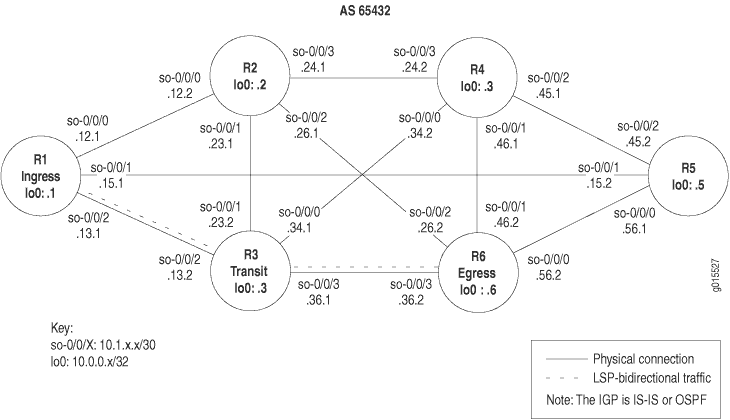 を検証するためのMPLSトポロジー
図12のMPLSネットワークは、以下のコンポーネントで構成されるSONETインターフェイスを持つルーターのみのネットワークを示しています。
-
AS 65432を使用したフルメッシュのIBGP(内部境界ゲートウェイプロトコル)トポロジー
-
すべてのルーターでMPLSとRSVP(Resource Reservation Protocol)が有効
-
新しいルートをネットワークにアドバタイズすることを許可するルーターR1およびR6の 送信静的 ポリシー
-
ルーターR1とR6間のLSP
図12に示したネットワークは、BGP(境界ゲートウェイプロトコル)フルメッシュネットワークです。ルートリフレクタとコンフェデレーションは、BGP学習したルートの伝播には使用されないため、各ルーターは、実行中のBGP他のすべてのルーターとBGPセッションを持つ必要があります。
ネットワークでの LSP 使用を確認するには、次の手順に従います。
イングレスルーターでのLSPの検証
目的
LSPが起動したときにその可用性を確認するには、ingressルーターの inet.3 ルーティングテーブルを調べます。 inet.3 ルーティングテーブルには、各 LSP のegressルーターのホストアドレスが含まれています。このルーティングテーブルは、BGPパケットを宛先のegressルーターにルーティングするためにイングレスルーターで使用されます。BGPは、ingressルーターの inet.3 ルーティングテーブルを使用して、ネクストホップアドレスの解決を支援します。
アクション
ingressルーターでLSPを検証するには、以下のJunos OSコマンドラインインターフェイス(CLI)運用モードコマンドを入力します。
user@host> show route table inet.3
出力例
コマンド名
user@R1> show route table inet.3
inet.3: 1 destinations, 1 routes (1 active, 0 holddown, 0 hidden)
+ = Active Route, - = Last Active, * = Both

10.0.0.6/32        *[RSVP/7] 4w0d 22:40:57, metric 20
                    > via so-0/0/2.0, label-switched-path R1-to-R6
意味
サンプル出力は、inet.3 ルーティングテーブルを示しています。デフォルトでは、BGPおよびMPLS仮想プライベートネットワーク(VPN)のみがinet.3ルートテーブルを使用してネクストホップ情報を解決できます。1 つの宛先がルートテーブル 10.0.0.6 にリストされています。この宛先(10.0.0.6)はRSVPによってシグナリングされ、アスタリスク(*)で示されるように、現在のアクティブなパスです。このルートのプロトコル優先度は 7 で、それに関連するメトリックは 20 です。ラベルスイッチ パスは、物理的なネクストホップ トランジット インターフェイスであるインターフェイス so-0/0/2.0 を介する R1 から R6 です。
通常、LSP の最後から 2 番目のルーターは、パケットのラベルをポップするか、ラベルを値 0 に変更します。最後から 2 番目のルーターがトップラベルをポップし、その下に IPv4 パケットがある場合、egressルーターは IPv4 パケットをルーティングし、IP ルーティングテーブル inet.0 を参照してパケットの転送方法を決定します。別のタイプのラベル(IPv4ではなく、LDP(ラベル配布プロトコル)トンネリングやVPNによって作成されたラベルなど)がトップラベルの下にある場合、egressルーターは inet.0 ルーティングテーブルを調べません。代わりに、転送の決定のために mpls.0 ルーティングテーブルを調べます。
最後から 2 番目のルーターがパケットのラベルを値 0 に変更した場合、egressルーターは 0 のラベルを削除し、IPv4 パケットが続くことを示します。パケットは、 inet.0 ルーティングテーブルによって転送決定のために調べられます。
トランジット ルーターまたはegressルーターがMPLSパケットを受信すると、MPLS転送テーブルの情報を使用して、LSP内の次のトランジットルーター、またはこのルーターがegressルーターであるかどうかを判断します。
BGPがネクストホッププレフィックスを解決すると、 inet.0 と inet.3 の両方のルーティングテーブルを調べて、優先度が最も低いネクストホップを探します。例えば、RSVPプリファレンス7はOSPFプリファレンス10よりも優先されます。RSVP シグナリングされた LSP は、BGP ネクストホップに到達するために使用されます。これは、BGPネクストホップがLSPエグレスアドレスと等しい場合のデフォルトです。BGPネクストホップがLSPを介して解決されると、BGPトラフィックはLSPを使用してBGPトランジットトラフィックを転送します。
トランジットルーターでのLSPの検証
目的
トランジットルーターの mpls.0 ルーティングテーブルを調べることで、LSPが起動したときにLSPの可用性を確認することができます。MPLS は、各 LSP 内の次のラベルスイッチ ルーターのリストを含む mpls.0 ルーティングテーブルを維持します。このルーティングテーブルは、LSPに沿って次のルーターにパケットをルーティングするためにトランジットルーターで使用されます。
アクション
トランジットルーターでLSPを検証するには、以下のJunos OS CLI運用モードコマンドを入力します。
user@host> show route table mpls.0
出力例
コマンド名
user@R3> show route table mpls.0
mpls.0: 5 destinations, 5 routes (5 active, 0 holddown, 0 hidden)
+ = Active Route, - = Last Active, * = Both

0                    * [MPLS/0] 7w3d 22:20:56, metric 1
                      Receive
1                    * [MPLS/0] 7w3d 22:20:56, metric 1
                      Receive
2                    * [MPLS/0] 7w3d 22:20:56, metric 1
                      Receive
100064               * [RSVP/7] 2w1d 04:17:36, metric 1
                     > via so-0/0/3.0, label-switched-path R1-to-R6
100064 (S=0)          * [RSVP/7] 2w1d 04:17:36, metric 1
                    > via so-0/0/3.0, label-switched-path R1-to-R6
意味
トランジット ルーター R3 からのサンプル出力には、ルート エントリーが MPLS ラベル エントリーの形式で表示されており、アクティブ エントリーが 5 つあるにもかかわらず、アクティブなルートが 1 つしかないことを示しています。
最初の 3 つの MPLS ラベルは、RFC 3032 で定義された予約済み MPLS ラベルです。これらのラベル値で受信したパケットは、処理のためにルーティングエンジンに送信されます。ラベル 0 は IPv4 explicit null ラベルです。ラベル 1 は IP ルーター アラート ラベルに相当する MPLS ラベルで、ラベル 2 は IPv6 explicit null ラベルです。
100064ラベルが付いた2つのエントリーは、同じLSP、R1からR6用です。MPLSヘッダーのスタック値が異なる場合があるため、2つのエントリーがあります。2番目のエントリ100064(S=0)は、スタックの深さが1ではなく、追加のラベル値がパケットに含まれていることを示しています。対照的に、100064 の最初のエントリーには、スタックの深さが 1 であることを示す推定 S=1 があり、それがパケット内の最後のラベルになります。デュアルエントリーは、これが最後から2番目のルーターであることを示しています。MPLSラベルスタックの詳細については、RFC 3032、MPLSラベルスタックエンコーディングを参照してください。
受信ラベルは MPLS パケットの MPLS ヘッダーであり、RSVP によってアップストリーム ネイバーに割り当てられます。ジュニパーネットワークスのルーターは、100,000〜1,048,575の範囲のRSVPトラフィックエンジニアリングLSPにラベルを動的に割り当てます。
ルーターは、ラベル100,000から始まり、16刻みでラベルを割り当てます。ラベル割り当ての順序は、100,000、100,016、100,032、100,048などです。割り当てられたラベルの最後には、ラベル番号が 100001 からやり直され、16 単位で増加します。ジュニパーネットワークスは、さまざまな目的のためにラベルを予約しています。 表 1 は、受信ラベルに対するさまざまなラベル範囲の割り当てを示しています。
|
受信ラベル |
ステータス |
|---|---|
|
0 〜 15 |
IETFによる予約 |
|
16 から 1023 |
静的LSP割り当て用に予約済み |
|
1024 〜 9999 |
内部使用(CCCラベルなど)用に予約されています |
|
10,000 〜 99,999 |
静的LSP割り当て用に予約済み |
|
100,000 〜 1,048,575 |
動的なラベル割り当て用に予約済み |
ロード バランシングが動作していることを確認する
目的
ロードバランシングを設定した後、トラフィックがパス全体で均等にロードバランシングされていることを確認します。このセクションでは、コマンド出力は、 ロードバランシングネットワークトポロジーで示したネットワーク例のロードバランシング設定を反映します。 clear コマンドは、LSPおよびインターフェイスカウンターをゼロにリセットして、値がロードバランシング設定の動作を反映するように使用します。
アクション
インターフェイスと LSP 全体でロードバランシングを検証するには、ingressルーターで以下のコマンドを使用します。
user@host# show configuration
インターフェイスと LSP 全体でロードバランシングを検証するには、トランジット ルーターで以下のコマンドを使用します。
user@host# show route
user@host# show route forwarding-table
user@host# show mpls lsp statistics
user@host# monitor interface traffic
user@host# clear mpls lsp statistics
user@host# clear interface statistics
出力例
コマンド名
以下のサンプル出力は、ingressルーター R1 での設定用です。
user@R1> show configuration | no-more
[...Output truncated...]
routing-options {
    [...Output truncated...]
     forwarding-table {
        export lbpp;
    }
}
[...Output truncated...]
policy-options {
     policy-statement lbpp {
        then {
            load-balance per-packet;
        }
    }
}
意味
ingressルーター R1上のshow configurationコマンドのサンプル出力は、ロードバランシングがlbppポリシーステートメントで正しく設定されていることを示しています。また、lbppポリシーは、[edit routing-options]階層レベルで転送テーブルにエクスポートされます。
出力例
以下のサンプル出力はトランジット ルーター R2 からのものです。
user@R2> show route 192.168.0.1 terse

inet.0: 25 destinations, 27 routes (25 active, 0 holddown, 0 hidden)
+ = Active Route, - = Last Active, * = Both
A Destination        P Prf   Metric 1   Metric 2  Next hop        AS path
* 192.168.0.1/32     O  10          3             so-0/0/1.0
                                                 >so-0/0/2.0
[...Output truncated...]
意味
トランジット ルーター R2で発行されたshow routeコマンドのサンプル出力は、ネットワークを介してループバックアドレスからR0(192.168.0.1)に至る2つのイコールコストパス(so-0/0/1およびso-0/0/2)を示しています。通常、山かっこ(>)はアクティブなルートを示しますが、この例ではそうではなく、次の 4 つのサンプル出力に示されています。
出力例
以下のサンプル出力はトランジット ルーター R2 からのものです。
user@R2> monitor interface traffic

R2                                Seconds: 65                  Time: 11:41:14

Interface    Link  Input packets        (pps)     Output packets        (pps)
 so-0/0/0      Up              0          (0)                  0          (0)
 so-0/0/1      Up            126          (0)              164659       (2128)
 so-0/0/2      Up          85219       (1004)              164598       (2128)
 so-0/0/3      Up              0          (0)                  0          (0)
 fe-0/1/0      Up         328954       (4265)              85475       (1094)
 fe-0/1/1      Up              0          (0)                  0          (0)
 fe-0/1/2      Up              0          (0)                  0          (0)
 fe-0/1/3      Up              0          (0)                  0          (0)
[...Output truncated...]
意味
トランジットルーター R2で発行されたmonitor interface trafficコマンドのサンプル出力では、出力トラフィックがso-0/0/1とso-0/0/2の2つのインターフェイス全体に均等に分配されていることがわかります。
出力例
以下のサンプル出力はトランジット ルーター R2 からのものです。
user@R2> show mpls lsp statistics
Ingress LSP: 0 sessions
Total 0 displayed, Up 0, Down 0

Egress LSP: 0 sessions
Total 0 displayed, Up 0, Down 0

Transit LSP: 5 sessions
To              From            State     Packets            Bytes LSPname
192.168.0.1     192.168.1.1     Up           87997         17951388 lsp1
192.168.0.1     192.168.1.1     Up           87997         17951388 lsp2
192.168.0.1     192.168.1.1     Up           87997         17951388 lsp3
192.168.0.1     192.168.1.1     Up           87997         17951388 lsp4
192.168.6.1     192.168.0.1     Up              0                0 r0-r1
Total 5 displayed, Up 5, Down 0
意味
トランジット ルーター R2で発行されたshow mpls lsp statisticsコマンドのサンプル出力では、出力トラフィックがingressルーター R6に設定された4つのLSP全体に均等に分配されていることがわかります。
出力例
以下のサンプル出力はトランジット ルーター R2 からのものです。
user@R2> show route forwarding-table destination 10.0.90.14
Routing table: inet
Internet:
Destination        Type RtRef Next hop           Type Index NhRef Netif
10.0.90.12/30      user     0                     ulst 262144     6
                                                  ucst   345     5 so-0/0/1.0
                                                  ucst   339     2 so-0/0/2.0
意味
トランジットルーター R2で発行されたshow route forwarding-table destinationコマンドのサンプル出力では、タイプフィールドにulstが表示されており、ロードバランシングが機能していることがわかります。タイプフィールドの2つのユニキャスト(ucst)エントリーは、LSPの2つのネクストホップです。
出力例
以下のサンプル出力はトランジット ルーター R2 からのものです。
user@R2> show route forwarding-table | find mpls
Routing table: mpls
MPLS:
Destination        Type RtRef Next hop           Type Index NhRef Netif
default            perm     0                    dscd    38     1
0                  user     0                    recv    37     3
1                  user     0                    recv    37     3
2                  user     0                    recv    37     3
100112             user     0                   Swap 100032       so-0/0/1.0
100128             user     0                   Swap 100048       so-0/0/1.0
100144             user     0 10.0.12.13        Swap 100096       fe-0/1/0.0
100160             user     0                   Swap 100112       so-0/0/2.0
100176             user     0                   Swap 100128       so-0/0/2.0
意味
トランジットルーター R2で発行された show route forwarding-table | find mpls コマンドのサンプル出力は、受信したラベルを含むMPLSルーティングテーブルを示しており、このルーターがネクストホップルーターにパケットを転送するために使用しています。このルーティングテーブルは、主にトランジットルーターで使用され、LSPに沿って次のルーターにパケットをルーティングします。プロトコルが有効化されると、 宛先 列の最初の 3 つのラベル(ラベル 0、ラベル 1、およびラベル 2)が MPLS によって自動的に入力されます。これらのラベルは、RFC 3032 で定義された予約済み MPLS ラベルです。ラベル 0 は IPv4 explicit null ラベルです。ラベル 1 は IP ルーター アラート ラベルに相当する MPLS で、ラベル 2 は IPv6 explicit null ラベルです。
宛先列の残りの 5 つのラベルは、ルーターがトラフィックを転送するために使用する非予約済みのラベルで、最後の列 Netif は、ラベル付きのトラフィックの送信に使用されるインターフェイスを示しています。非予約済みラベルの場合、2番目のタイプ列は、一致するパケットで実行された操作を示しています。この例では、非予約済みのパケットはすべて発信パケット ラベルに交換されます。例えば、ラベル100112を持つパケットは、インターフェイスso-0/0/1.0から押し出される前に、そのラベルが100032に交換されます。
不均一な帯域幅のロードバランシングの動作検証
目的
ルーターがLSPパス間で不等コストロードバランシングを実行している場合、 show route detail コマンドは、使用されている各ネクストホップに関連付けられたバランスフィールドを表示します。
アクション
RSVP LSPのロードバランシングが不均一であることを確認するには、以下のJunos OS CLI動作モードコマンドを使用します。
user@host> show route protocol rsvp detail
user@host> show mpls lsp statistics
出力例
コマンド名
user@R1> show route protocol rsvp detail

inet.0: 25 destinations, 25 routes (25 active, 0 holddown, 0 hidden)
10.0.90.14/32 (1 entry, 1 announced)
        State: <FlashAll>
        *RSVP   Preference: 7
                Next-hop reference count: 7
                Next hop: 10.0.12.14 via fe-0/1/0.0 weight 0x1  balance 10%
                 Label-switched-path lsp1
                Label operation: Push 100768
                Next hop: 10.0.12.14 via fe-0/1/0.0 weight 0x1  balance 20%
                 Label-switched-path lsp2
                Label operation: Push 100736
                Next hop: 10.0.12.14 via fe-0/1/0.0 weight 0x1  balance 30%,
						selected
                 Label-switched-path lsp3
                Label operation: Push 100752
                Next hop: 10.0.12.14 via fe-0/1/0.0 weight 0x1  balance 40%
                 Label-switched-path lsp4
                Label operation: Push 100784
                State: <Active Int>
                Local AS: 65432
                Age: 8:03       Metric: 4
                Task: RSVP
                Announcement bits (2): 0-KRT 4-Resolve tree 1
                AS path: I
inet.3: 1 destinations, 1 routes (1 active, 0 holddown, 0 hidden)
192.168.0.1/32 (1 entry, 1 announced)
        State: <FlashAll>
        *RSVP   Preference: 7
                Next-hop reference count: 7
                Next hop: 10.0.12.14 via fe-0/1/0.0 weight 0x1 balance 10%
                Label-switched-path lsp1
                Label operation: Push 100768
                Next hop: 10.0.12.14 via fe-0/1/0.0 weight 0x1 balance 20%
                Label-switched-path lsp2
                Label operation: Push 100736
                Next hop: 10.0.12.14 via fe-0/1/0.0 weight 0x1 balance 30%
                Label-switched-path lsp3
                Label operation: Push 100752
                Next hop: 10.0.12.14 via fe-0/1/0.0 weight 0x1 balance 40%, selected
                Label-switched-path lsp4
                Label operation: Push 100784
                State: <Active Int>
                Local AS: 65432
                Age: 8:03       Metric: 4
                Task: RSVP
                Announcement bits (1): 1-Resolve tree 1
                AS path: I

user@R1> show mpls lsp statistics
Ingress LSP: 4 sessions
To              From            State     Packets            Bytes LSPname
192.168.0.1     192.168.1.1     Up           10067            845628  lsp1
192.168.0.1     192.168.1.1     Up           20026          1682184  lsp2
192.168.0.1     192.168.1.1     Up           29796           2502864  lsp3
192.168.0.1     192.168.1.1     Up           40111           3369324  lsp4
Total 4 displayed, Up 4, Down 0

Egress LSP: 1 sessions
To              From            State     Packets            Bytes LSPname
192.168.1.1     192.168.0.1     Up             NA               NA r0-r1
Total 1 displayed, Up 1, Down 0

Transit LSP: 0 sessions
Total 0 displayed, Up 0, Down 0
意味
ingressルーター R1 からの出力例では、 Balance: xx% フィールドで示されるように、LSP 帯域幅設定に従ってトラフィックが分配されることを示しています。例えば、 lsp1 には10Mbpsの帯域幅が設定されており、 バランス:10% フィールドに反映されています。
tracerouteコマンドを使用したMPLSラベルの検証
目的
tracerouteコマンドを使用して、LSP上でパケットが送信されていることを確認できます。
アクション
ラベルMPLS検証するには、リモートホストのIPアドレスまたは名前CLI host-name Junos OS動作モードコマンドを入力します。
user@host> traceroute host-name
サンプル出力 1
コマンド名
user@R1> traceroute 100.100.6.1
traceroute to 100.100.6.1 (100.100.6.1), 30 hops max, 40 byte packets
 1  10.1.12.2 (10.1.12.2)  0.861 ms  0.718 ms  0.679 ms
      MPLS Label=100048 CoS=0 TTL=1 S=1
 2  10.1.24.2 (10.1.24.2)  0.822 ms  0.731 ms  0.708 ms
      MPLS Label=100016 CoS=0 TTL=1 S=1
 3  10.1.46.2 (10.1.46.2)  0.571 ms !N  0.547 ms !N  0.532 ms !N
サンプル出力2
コマンド名
user@R1> traceroute 10.0.0.6
traceroute to 10.0.0.6 (10.0.0.6), 30 hops max, 40 byte packets
 1  10.1.13.2 (10.1.13.2)  0.605 ms  0.548 ms  0.503 ms
 2  10.0.0.6 (10.0.0.6)  0.761 ms  0.676 ms  0.675 ms
意味
サンプル出力 1 は、ネットワークを介してパケットを転送するために MPLS ラベルが使用されていることを示しています。出力には、ラベル値(MPLS Label=100048)、寿命時間値(TTL=1)、スタックビット値(S=1)が含まれます。
MPLSラベルフィールドは、特定のLSPへのパケットを識別するために使用されます。これは 20 ビット フィールドで、最大値は (2^^20-1)、つまり約 1,000,000 です。
TTL値には、このMPLSパケットがネットワークを通過できるホップ数の制限が含まれています(1)。ホップごとにデクリメントされ、TTL値が1を下回るとパケットは廃棄されます。
スタック最下段のビット値(S=1)は、スタックの最後のラベルであり、この MPLS パケットに 1 つのラベルが関連付けられていることを示します。Junos OSのMPLS実装は、Mシリーズルーターで3、Tシリーズプラットフォームで最大5のスタッキング深さをサポートしています。MPLSラベルスタックの詳細については、RFC 3032、 MPLSラベルスタックエンコーディングを参照してください。
サンプル出力1にMPLSラベルが表示されるのは、 traceroute コマンドがBGP宛に発行され、そのルートのBGPネクストホップがLSPエグレスアドレスであるためです。Junos OSデフォルトの動作では、BGPネクストホップがLSPエグレスアドレスと等しい場合、BGPトラフィックにLSPを使用します。
サンプル出力2は、 traceroute コマンドの出力にMPLSラベルが表示されていないことを示しています。BGPネクストホップがLSPの出口アドレスと等しくない場合、または宛先がIGPルートの場合、BGPトラフィックはLSPを使用しません。BGPトラフィックはLSPを使用する代わりに、IGP(この場合はIS-IS)を使用してエグレスアドレス(R6)に到達しています。
GMPLS および GRE トンネルのトラブルシューティング
問題点
説明
GMPLS の論理制御チャネルは、ポイントツーポイント リンクであり、何らかの形式の IP 到達可能性を持っていなければなりません。ブロードキャスト インターフェイス上、または制御チャネル ピア間に複数のホップがある場合、制御チャネルに GRE トンネルを使用します。GMPLS および GRE トンネルの詳細については、 Junos MPLS アプリケーション構成ガイド と Junos ユーザー ガイドを参照してください。
GMPLS制御チャネルのGREトンネルを設定するためにトンネルPICは必要ありません。代わりに、ハードウェアベースのgr-fpc/pic/portインターフェイスではなく、ソフトウェアベースのgréインターフェイスを使用します。
ソフトウェアベースの GRE インターフェイスの制限により、GMPLS制御チャネルはソフトウェアベース GRE インターフェイスの唯一のサポートされている用途です。その他の用途は明示的にサポートされておらず、アプリケーション障害が発生する可能性があります。
以下の例は、 基本的な GRE インターフェイス設定を示しています。この場合、トンネル送信元はローカルルーターのループバックアドレスであり、宛先アドレスはリモートルーターのループバック宛先です。トンネル宛先のネクスト ホップがあるトラフィックは、トンネルを使用します。インターフェイスを通過するすべてのトラフィックでトンネルが自動的に使用されるわけではありません。トンネル宛先がネクストホップのトラフィックのみ、トンネルを使用します。
出力例
user@R1> show configuration interfaces
[...Output truncated...]
gre {
    unit 0 {
        tunnel {
            source 10.0.12.13;
            destination 10.0.12.14;
        }
        family inet {
            address 10.35.1.6/30;
        }
        family mpls;
    }
}
出力例
以下の show interfaces コマンドの出力例は、カプセル化の種類とヘッダー、最高速度、論理インターフェイスを通過するパケット、宛先、論理アドレスを示しています。
user@R1> show interfaces gre
Physical interface: gre, Enabled, Physical link is Up
  Interface index: 10, SNMP ifIndex: 8
   Type: GRE, Link-level type: GRE,  MTU: Unlimited, Speed: Unlimited
  Device flags   : Present Running
  Interface flags: Point-To-Point SNMP-Traps
    Input packets : 0
    Output packets: 0

  Logical interface gre.0 (Index 70) (SNMP ifIndex 47)
    Flags: Point-To-Point SNMP-Traps 0x4000
     IP-Header 10.0.12.14:10.0.12.13:47:df:64:0000000000000000
     Encapsulation: GRE-NULL
    Input packets : 171734
    Output packets: 194560
    Protocol inet, MTU: 1476
      Flags: None
      Addresses, Flags: Is-Preferred Is-Primary
         Destination: 10.35.1.4/30, Local: 10.35.1.6, Broadcast: 10.35.1.7
    Protocol mpls, MTU: 1464
      Flags: None
以下は、GREトンネルを使用してGMPLS LSPを設定する際のさまざまな要件です。
-
データ チャネルは、同じタイプのインターフェイスで開始および終了する必要があります。
-
制御チャネルは、同じまたは異なるインターフェイス タイプで開始および終了する GRE トンネルです。
-
GREトンネルは、階層レベルの peer-interface
peer-nameステートメントで[edit protocol ospf]間接的に設定する必要があります。 -
GREインターフェイスは、
[edit protocols ospf]および[edit protocols rsvp]階層レベルで無効にする必要があります。 -
データおよび制御チャネルは、LMP 設定で正しく定義する必要があります。
-
任意で、
no-cspfステートメントでCSPF(制限付き最短パスファースト)を無効化できます。
このケースは、GREトンネルのエンドポイントの不正な設定に焦点を当てています。ただし、同様のプロセスやコマンドを使用して、他の GRE トンネル問題を診断できます。 図13 は、GREインターフェイスを介してトンネリングされたMPLSを使用したネットワークトポロジーを示しています。
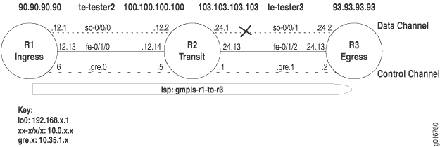
図13のMPLSネットワークトポロジーは、以下のコンポーネントで構成されたGREトンネルで設定されたジュニパーネットワークスルーターを示しています。
-
ingressルーターからegressルーターへの厳密なGMPLS LSPパス。
-
ingressルーターでは、[edit protocol mpls label-switched-path lsp-name]階層レベルの
no-cspfステートメントでCSPFが無効化されました。 -
すべてのルーターの[edit protocols link-management]階層レベルの
peerステートメント内のトラフィック制御リンクと制御チャネル。 -
すべてのルーターで設定された OSPF および OSPF トラフィック制御。
-
すべてのルーター上の OSPF と RSVP の両方における ピア インターフェイス への参照。
-
R2 と R3 間のスイッチングタイプの問題。
症状
図 13 に示すネットワーク内の LSP は、非常に似た情報を示す show mpls lsp コマンドと show rsvp session コマンドの出力に示されているように、ダウンしています。show mpls lspコマンドは、ルーターに設定されたすべてのLSPと、すべてのトランジットおよびエグレスLSPを表示します。show rsvp session コマンドは、RSVP セッションに関する概要情報を表示します。いずれのコマンドを使用して、LSP の状態を検証できます。この場合、LSP gmpls-r1-to-r3はダウンしています(Dn)。
出力例
user@R1> show mpls lsp
Ingress LSP: 1 sessions
To              From            State Rt ActivePath       P     LSPname
192.168.4.1     192.168.1.1     Dn     0 -                      gmpls-r1-to-r3
Bidir
Total 1 displayed, Up 0, Down 1

Egress LSP: 0 sessions
Total 0 displayed, Up 0, Down 0

Transit LSP: 0 sessions
Total 0 displayed, Up 0, Down 0

user@R1>  show rsvp session
Ingress RSVP: 1 sessions
To              From            State   Rt Style Labelin Labelout LSPname
192.168.4.1     192.168.1.1     Dn       0  0  -       -        - gmpls-r1-to-r3
Bidir
Total 1 displayed, Up 0, Down 1

Egress RSVP: 0 sessions
Total 0 displayed, Up 0, Down 0

Transit RSVP: 0 sessions
Total 0 displayed, Up 0, Down 0
原因
GMPLS LSP の問題の原因は、GMPLS データ チャネルの両方における異なるインターフェイス タイプの設定です。
コマンドのトラブルシューティング
Junos OSには、問題のトラブルシューティングに役立つコマンドが含まれています。このトピックでは、各コマンドの簡単な説明、サンプル出力、問題に関連する出力に関する考察を紹介します。
GMPLS 問題のトラブルシューティング時に以下のコマンドを使用できます。
user@host> show mpls lsp extensive
user@host> show rsvp session detail
user@host> show link-management peer
user@host> show link-management te-link
user@host> show configuration protocols mpls
user@host> monitor start filename
user@host> show log filename
出力例
トランジット ルーター R1 で show mpls lsp extensive コマンドを使用すると、ルーター上で通過、終端、設定されるすべての LSP に関する詳細情報が表示されます。
user@R1> show mpls lsp extensive
Ingress LSP: 1 sessions

192.168.4.1
  From: 192.168.1.1, State: Dn, ActiveRoute: 0, LSPname: gmpls-r1-to-r3
  Bidirectional
  ActivePath: (none)
  LoadBalance: Random
  Encoding type: SDH/SONET, Switching type: PSC-1, GPID: IPv4
  Primary   p1               State: Dn
    SmartOptimizeTimer: 180
    8 Dec 20 18:08:02 192.168.4.1: MPLS label allocation failure [3 times]
    7 Dec 20 18:07:53 Originate Call
    6 Dec 20 18:07:53 Clear Call
    5 Dec 20 18:07:53 Deselected as active
    4 Dec 20 18:06:13 Selected as active path
    3 Dec 20 18:06:13 Record Route:  100.100.100.100 93.93.93.93
    2 Dec 20 18:06:13 Up
    1 Dec 20 18:06:13 Originate Call
  Created: Wed Dec 20 18:06:12 2006
Total 1 displayed, Up 0, Down 1

Egress LSP: 0 sessions
Total 0 displayed, Up 0, Down 0

Transit LSP: 0 sessions
Total 0 displayed, Up 0, Down 0
意味
show mpls lsp extensive コマンドのサンプル出力では、出力のログセクションにエラーメッセージ(MPLSラベル割り当て失敗)が表示されます。このLSPイベントは、MPLSプロトコルまたはfamily mplsステートメントが正しく設定されていないことを示しています。LSP イベントの前に IP アドレスがある場合、そのアドレスは通常、MPLS 設定エラーが発生したルーターです。この場合、lo0アドレスが192.168.4.1(R3)のルーターにMPLS設定エラーが発生しているようです。
出力例
show rsvp session detail コマンドを使用すると、RSVP セッションに関する詳細情報が表示されます。
user@R1> show rsvp session detail
Ingress RSVP: 1 sessions

192.168.4.1
  From: 192.168.1.1,  LSPstate: Dn, ActiveRoute: 0
   LSPname: gmpls-r1-to-r3, LSPpath: Primary
  Bidirectional, Upstream label in: 21253, Upstream label out: -
  Suggested label received: -,  Suggested label sent: 21253
  Recovery label received: -, Recovery label sent: -
   Resv style: 0 - , Label in: -, Label out: -
  Time left:    -, Since: Wed Dec 20 18:07:53 2006
  Tspec: rate 0bps size 0bps peak 155.52Mbps m 20 M 1500
  Port number: sender 2 receiver 46115 protocol 0
  PATH rcvfrom: localclient
  Adspec: sent MTU 1500
  Path MTU: received 0
  PATH sentto: 10.35.1.5 (tester2) 3 pkts
   Explct route: 100.100.100.100 93.93.93.93
   Record route: <self> ...incomplete
Total 1 displayed, Up 0, Down 1

Egress RSVP: 0 sessions
Total 0 displayed, Up 0, Down 0

Transit RSVP: 0 sessions
Total 0 displayed, Up 0, Down 0
意味
show rsvp session detail コマンドのサンプル出力は、LSP gmpls-r1-to-r3がダウンしていることを示しています(LSPstate:Dn)。ルート記録が不完全なので、明示的なルート 100.100.100.100 93.93.93.93 に問題があることを示しています。アドレス 100.100.100.100 は R2 so-0/0/0 上のデータ チャネルであり、アドレス 93.93.93.93 は R3 上のデータ チャネルです。
出力例
show link-management peer コマンドを使用すると、MPLSピアリンク情報が表示されます。
user@R1> show link-management peer
Peer name: tester2, System identifier: 48428
  State: Up, Control address:  10.35.1.5
   Control-channel                   State
   gre.0                              Active
  TE links:
   tester2

user@R2> show link-management peer
Peer name: tester2, System identifier: 48428
 State: Up, Control address: 10.35.1.6
   Control-channel                   State
   gre.0                              Active
  TE links:
   te-tester2

Peer name: tester3 , System identifier: 48429
  State: Up , Control address: 10.35.1.2
   Control-channel                   State
   gre.1                              Active
  TE links:
   te-tester3

user@R3> show link-management peer
Peer name: tester3, System identifier: 48429
  State: Up, Control address: 10.35.1.1
   Control-channel                   State
   gre.0                              Active
  TE links:
   te-tester3
意味
show link-management peer コマンドの図13のサンプルネットワーク内のすべてのルーターからの出力例は、すべての制御チャネルが立ち上がっていることを示しています。出力の詳細な分析は、以下の情報を示しています。
-
トラブルシューティングを容易にするために隣接するルーターで同じになっているピアの名前、 tester2 または tester3。
-
ピアの内部識別子、tester2 の 48428、tester3 の 48429。内部識別子は、0から64,000までの値の範囲です。
-
ピアの状態(アップまたはダウン)。この場合、すべてのピアが立ち上がっています。
-
制御チャネルが確立されているアドレス( 例:10.35.1.5)。
-
制御チャネルの状態(アップ、ダウン、またはアクティブ)。
-
ピアによって管理されているトラフィック制御リンクは、制御チャネル gre.0 が tester3によって管理されていることを示しています。
出力例
show link-management te-link コマンドを使用すると、MPLS(MPLS)トラフィック制御転送パスの設定に使用するリソースが表示されます。
user@R1> show link-management te-link
TE link name:  tester2, State: Up
  Local identifier: 2005, Remote identifier: 21253, Local address: 90.90.90.90, Remote address: 100.100.100.100,
  Encoding: SDH/SONET, Switching: PSC-1, Minimum bandwidth: 155.52Mbps, Maximum bandwidth: 155.52Mbps, Total bandwidth: 155.52Mbps,
  Available bandwidth: 0bps
    Name        State Local ID  Remote ID      Bandwidth  Used   LSP-name
     so-0/0/0    Up       21253      21253      155.52Mbps   Yes   gmpls-r1-to-r3

user@R2> show link-management te-link
 TE link name:  te-tester2, State: Up
  Local identifier: 7002, Remote identifier: 22292, Local address: 100.100.100.100, Remote address: 90.90.90.90,
  Encoding: SDH/SONET, Switching: PSC-1, Minimum bandwidth: 155.52Mbps, Maximum bandwidth: 155.52Mbps, Total bandwidth: 155.52Mbps,
  Available bandwidth: 0bps
    Name        State Local ID  Remote ID      Bandwidth  Used   LSP-name
    so-0/0/0    Up       21253      21253     155.52Mbps   Yes   gmpls-r1-to-r3
TE link name:  te-tester3, State: Up
  Local identifier: 7003, Remote identifier: 21254, Local address: 103.103.103.103, Remote address: 93.93.93.93,
  Encoding: SDH/SONET, Switching: PSC-1, Minimum bandwidth: 155.52Mbps, Maximum bandwidth: 155.52Mbps, Total bandwidth: 155.52Mbps,
  Available bandwidth: 0bps
    Name        State Local ID  Remote ID      Bandwidth  Used   LSP-name
    so-0/0/1    Up       21252      21252     155.52Mbps   Yes  gmpls-r1-to-r3

user@R3> show link-management te-link
 TE link name:  te-tester3, State: Up
  Local identifier: 7003, Remote identifier: 21254,  Local address: 93.93.93.93,
Remote address: 103.103.103.103,
  Encoding: SDH/SONET, Switching: PSC-1, Minimum bandwidth: 0bps, Maximum bandwidth: 0bps, Total bandwidth: 0bps,
  Available bandwidth: 0bps
    Name        State Local ID  Remote ID      Bandwidth Used  LSP-name
    so-0/0/1    Dn       21252      21252     155.52Mbps    No
意味
図13のネットワーク内の3つのルーターで発行されたshow link-management te-link コマンドのサンプル出力は、トラフィック制御リンクte-tester2とte-tester3に割り当てられたリソースを示しています。リソースは、SONET インターフェイス so-0/0/0 および so-0/0/1 です。R1 および R2 では、使用フィールドに「はい」と示されているように、SONET インターフェイスが LSP gmpls-r1-to-r3 に使用されますただし、R3 の SONET インターフェイス so-0/0/1 はダウン(Dn)されており、LSP には使用されていません(使用番号)。R3 の SONET インターフェイスがダウンしている理由を把握するには、さらに調査する必要があります。
サンプル出力
show log filename コマンドを使用して、指定されたログファイルの内容を表示します。この場合、ログファイルrsvp.logは[edit protocols rsvp traceoptions]階層レベルで設定されます。ログ ファイルが設定されている場合、monitor start filename コマンドを発行して、ファイルへのメッセージのログ記録を開始する必要があります。
user@R1> show configuration protocols rsvp
traceoptions {
    file rsvp.log size 3m world-readable;
    flag state detail;
    flag error detail;
    flag packets detail;
}

user@R1> monitor start rsvp.log
パイプ ( | ) の後に入力された [エラー検索] オプションは、用語 [エラー] のインスタンスを出力で検索します。
出力例
user@R3>
show log rsvp.log | find Error
Dec 28 17:23:32  Error  Len 20 Session preempted flag 0 by 192.168.4.1 TE-link 103.103.103.103
[...Output truncated...]
Dec 28 17:23:32 RSVP new resv state,session 192.168.4.1(port/tunnel ID 46115 Ext-ID 192.168.1.1)Proto 0
Dec 28 17:23:32         RSVP-LMP reset LMP request for gmpls-r1-to-r3
Dec 28 17:23:32         RSVP->LMP request -  resource for LSP gmpls-r1-to-r3
Dec 28 17:23:32         LMP->RSVP resource request gmpls-r1-to-r3 failed cannot find resource  encoding type SDH/SONET remote label 21252 bandwidth bw[0
Dec 28 17:23:32         RSVP-LMP reset LMP request for gmpls-r1-to-r3
Dec 28 17:23:32 RSVP originate PathErr 192.168.4.1->192.168.2.1 MPLS label allocation failure LSP gmpls-r1-to-r3(2/46115)
Dec 28 17:23:32 RSVP send PathErr 192.168.4.1->192.168.2.1 Len=196 tester3
Dec 28 17:23:32   Session7 Len 16 192.168.4.1(port/tunnel ID 46115 Ext-ID 192.168.1.1) Proto 0
Dec 28 17:23:32   Hop      Len 20 192.168.4.1/0x086e4770 TE-link 103.103.103.103
Dec 28 17:23:32   Error    Len 20 MPLS label allocation failure flag 0 by 192.168.4.1 TE-link 103.103.103.103
Dec 28 17:23:32   Sender7  Len 12 192.168.1.1(port/lsp ID  2)
Dec 28 17:23:32   Tspec    Len 36 rate 0bps size 0bps peak 155.52Mbps m 20 M 1500
Dec 28 17:23:32   ADspec   Len 48 MTU 1500
Dec 28 17:23:32   RecRoute Len 20  103.103.103.103 90.90.90.90
Dec 28 17:23:32   SuggLabel Len  8  21252
Dec 28 17:23:32   UpstrLabel Len  8  21252
意味
show log rsvp.log コマンドのegressルーター R3からのサンプル出力は、ログファイルから取得されたスニペットです。このスニペットは、LSP gmpls-r1-to-r3 の LMP(リンク管理プロトコル)リソース要求を示しています。リクエストにはエンコード タイプ(SDH/SONET)の問題があり、R2 と R3 を接続する SONET インターフェイスにエラーがある可能性があることを示しています。R2 および R3 での LMP の設定については、さらに調査する必要があります。
出力例
show configuration statement-path コマンドを使用して、特定の設定階層を表示します。このインスタンスでは、link-managementです。
user@R2> show configuration protocols link-management
te-link te-tester2 {
    local-address 100.100.100.100;
    remote-address 90.90.90.90;
    remote-id 22292;
    interface so-0/0/0 {
        local-address 100.100.100.100;
        remote-address 90.90.90.90;
        remote-id 21253;
    }
}
te-link te-tester3  {
    local-address 103.103.103.103;
    remote-address 93.93.93.93;
    remote-id 21254;
     interface so-0/0/1  {
        local-address 103.103.103.103;
        remote-address 93.93.93.93;
        remote-id 21252;
    }
}
peer tester2 {
    address 10.35.1.6;
    control-channel gre.0;
    te-link te-tester2;
}
peer tester3 {
    address 10.35.1.2;
    control-channel gre.1;
    te-link te-tester3;
}

user@R3> show configuration protocols link-management
te-link te-tester3  {
    local-address 93.93.93.93;
    remote-address 103.103.103.103;
    remote-id 21254;
    }
     interface at-0/3/1 {
        local-address 93.93.93.93;
        remote-address 103.103.103.103;
        remote-id 21252;
    }
}
peer tester3 {
    address 10.35.1.1;
    control-channel gre.0;
    te-link te-tester3;
}
意味
コマンドルータートランジット R2 と ingressルーター R3 からの show configuration protocols link-management コマンドのサンプル出力は、2 つのルーターのインターフェイス タイプが異なることを示しています。トランジット ルーター R2 の te-tester3 に割り当てられたリソースは SONET インターフェイスであり、egressルーター R3 の te-tester3 に割り当てられたリソースは ATM インターフェイスです。データまたは制御チャネルの各エンドのインターフェイスタイプは同じタイプである必要があります。この場合、エンドは SONET または ATM である必要があります。
ソリューション
ソリューション
GMPLS LSP のいずれかのエンドでインターフェイスまたはカプセル化のタイプが異なる場合の解決策は、インターフェイス タイプが両端で同じであることを確認することです。この場合、 ATM インターフェイスは R3 のリンク管理設定から削除され、代わりに SONET インターフェイスが設定されます。
以下のコマンドは、GMPLS LSP が立ち上がっていて、データ チャネルを使用していることを検証するための正しい設定とコマンドを示しています。
user@R3> show configuration protocols link-management
user@R3> show mpls lsp
user@R3> show link-management te-link
出力例
user@R3> show configuration protocols link-management
te-link te-tester3 {
    local-address 93.93.93.93;
    remote-address 103.103.103.103;
    remote-id 21254;
     interface so-0/0/1 { # SONET interface replaces the incorrect ATM interface
        local-address 93.93.93.93;
        remote-address 103.103.103.103;
        remote-id 21252;
    }
}
peer tester3 {
    address 10.35.1.1;
    control-channel gre.0;
    te-link te-tester3;
}

user@R3> show mpls lsp
Ingress LSP: 0 sessions
Total 0 displayed, Up 0, Down 0
Egress LSP: 1 sessions
To              From            State   Rt Style Labelin Labelout LSPname
192.168.4.1     192.168.1.1     Up       0  1 FF   21252        - gmpls-r1-to-r3
Bidir
Total 1 displayed, Up 1, Down 0

Transit LSP: 0 sessions
Total 0 displayed, Up 0, Down 0

user@R3> show link-management te-link
 TE link name: te-tester3, State: Up
  Local identifier: 7003, Remote identifier: 21254, Local address: 93.93.93.93, Remote address: 103.103.103.103,
  Encoding: SDH/SONET, Switching: PSC-1, Minimum bandwidth: 155.52Mbps, Maximum bandwidth: 155.52Mbps, Total bandwidth: 155.52Mbps,
  Available bandwidth: 0bps
    Name        State Local ID  Remote ID      Bandwidth Used  LSP-name
     so-0/0/1    Up       21252      21252     155.52Mbps  Yes  gmpls-r1-to-r3
意味
ingressルーター R3からのshow protocols link-management、show mpls lsp、および show link-management te-link コマンドのサンプル出力は、問題が解決されたことを示しています。LMP が正しく設定され、LSP gmpls-r1-to-r3 が立ち上がっており、データチャネル so-0/0/1 を使用しています。
まとめ
結論としては、GMPLS データ チャネルの両方のエンドは同じカプセル化またはインターフェイス タイプでなければなりません。このケースは、データ チャネルの正しい設定を示しています。原理は制御チャネルについても同じです。
ルーター設定
ネットワーク内のingressルーターの設定を示す出力。パイプ ( | ) の後に入力された no-more オプションは、出力が端末画面の長さよりも長い場合に出力にページ番号が付けられないようにします。
出力例
以下のサンプル出力は、ingressルーター R1 のものです。
user@R1>  show configuration | no-more
[...Output truncated...]
interfaces {
    so-0/0/0 {
        unit 0 {
            family inet {
                address 10.0.12.1/32 {
                    destination 10.0.12.2;
                }
            }
            family mpls;
        }
    }
    fe-0/1/0 {
        unit 0 {
            family inet {
                address 10.0.12.13/30;
            }
            family mpls;
        }
    }
    fxp0 {
        unit 0 {
            family inet {
                address 192.168.70.143/21;
            }
        }
    }
    gre {
        unit 0 {
            tunnel {
                source 10.0.12.13;
                destination 10.0.12.14;
            }
            family inet {
                address 10.35.1.6/30;
            }
            family mpls;
        }
    }
    lo0 {
        unit 0 {
            family inet {
                address 192.168.1.1/32;
            }
        }
    }
}
routing-options {
    static {
        /* corporate and alpha net */
        route 172.16.0.0/12 {
            next-hop 192.168.71.254;
            retain;
            no-readvertise;
        }
        /* old lab nets */
        route 192.168.0.0/16 {
            next-hop 192.168.71.254;
            retain;
            no-readvertise;
        }
        route 0.0.0.0/0 {
            discard;
            retain;
            no-readvertise;
        }
    }
    router-id 192.168.1.1;
    autonomous-system 65432;
}
protocols {
    rsvp {
        traceoptions {
            file rsvp.log size 3m world-readable;
            flag state detail;
            flag error detail;
            flag packets detail;
        }
        interface fxp0.0 {
            disable;
        }
        interface all;
        interface lo0.0;
        interface gre.0 {
            disable;
        }
        peer-interface tester2;
    }
    mpls {
        label-switched-path gmpls-r1-to-r3 {
            from 192.168.1.1;
            to 192.168.4.1;
            lsp-attributes {
                switching-type psc-1;
                encoding-type sonet-sdh;
            }
            no-cspf;
            primary p1;
        }
        path p1 {
            100.100.100.100 strict;
            93.93.93.93 strict;
        }
        interface all;
    }
    ospf {
        traffic-engineering;
        area 0.0.0.0 {
            interface lo0.0;
            interface fe-0/1/0.0;
            interface fxp0.0 {
                disable;
            }
            interface gre.0 {
                disable;
            }
            peer-interface tester2;
        }
    }
    link-management {
        te-link tester2 {
            local-address 90.90.90.90;
            remote-address 100.100.100.100;
            remote-id 21253;
            interface so-0/0/0 {
                local-address 90.90.90.90;
                remote-address 100.100.100.100;
                remote-id 21253;
            }
        }
        peer tester2 {
            address 10.35.1.5;
            control-channel gre.0;
            te-link tester2;
        }
    }
}
出力例
以下のサンプル出力はトランジット ルーター R2 のものです。
user@R2>show configuration | no-more
[...Output truncated...]
interfaces {
    so-0/0/0 {
        unit 0 {
            family inet {
                address 10.0.12.2/32 {
                    destination 10.0.12.1;
                }
            }
            family mpls;
        }
    }
    so-0/0/1 {
        unit 0 {
            family inet {
                address 10.0.24.1/32 {
                    destination 10.0.24.2;
                }
            }
            family mpls;
        }
    }
    fe-0/1/0 {
        unit 0 {
            family inet {
                address 10.0.12.14/30;
            }
            family mpls;
        }
    }
    fe-0/1/2 {
        unit 0 {
            family inet {
                address 10.0.24.13/30;
            }
            family mpls;
        }
    }
    fxp0 {
        unit 0 {
            family inet {
                address 192.168.70.144/21;
            }
        }
    }
    gre {
        unit 0 {
            tunnel {
                source 10.0.12.14;
                destination 10.0.12.13;
            }
            family inet {
                address 10.35.1.5/30;
            }
            family mpls;
        }
        unit 1 {
            tunnel {
                source 10.0.24.13;
                destination 10.0.24.14;
            }
            family inet {
                address 10.35.1.1/30;
            }
            family mpls;
        }
    }
    lo0 {
        unit 0 {
            family inet {
                address 192.168.2.1/32;
            }
        }
    }
}
routing-options {
    static {
        route 172.16.0.0/12 {
            next-hop 192.168.71.254;
            retain;
            no-readvertise;
        }
        route 192.168.0.0/16 {
            next-hop 192.168.71.254;
            retain;
            no-readvertise;
        }
        route 0.0.0.0/0 {
            discard;
            retain;
            no-readvertise;
        }
    }
    router-id 192.168.2.1;
    autonomous-system 65432;
}
protocols {
    rsvp {
        traceoptions {
            file rsvp.log size 3m world-readable;
            flag packets detail;
            flag state detail;
            flag error detail;
        }
        interface fxp0.0;
        interface lo0.0;
        interface all;
        interface gre.0 {
            disable;
        }
        peer-interface tester2;
        peer-interface tester3;
    }
    mpls {
        interface all;
    }
    ospf {
        traffic-engineering;
        area 0.0.0.0 {
            interface lo0.0;
            interface fxp0.0 {
                disable;
            }
            interface gre.0 {
                disable;
            }
            interface fe-0/1/0.0;
            interface fe-0/1/2.0;
            interface gre.1 {
                disable;
            }
            peer-interface tester2;
            peer-interface tester3;
        }
    }
    link-management {
        te-link te-tester2 {
            local-address 100.100.100.100;
            remote-address 90.90.90.90;
            remote-id 22292;
            interface so-0/0/0 {
                local-address 100.100.100.100;
                remote-address 90.90.90.90;
                remote-id 21253;
            }
        }
        te-link te-tester3 {
            local-address 103.103.103.103;
            remote-address 93.93.93.93;
            remote-id 21254;
            interface so-0/0/1 {
                local-address 103.103.103.103;
                remote-address 93.93.93.93;
                remote-id 21252;
            }
        }
        peer tester2 {
            address 10.35.1.6;
            control-channel gre.0;
            te-link te-tester2;
        }
        peer tester3 {
            address 10.35.1.2;
            control-channel gre.1;
            te-link te-tester3;
        }
    }
}
出力例
以下のサンプル出力は、egressルーター R3 のものです。
user@R3> show configuration | no-more
[...Output truncated...]
interfaces {
    so-0/0/1 {
        unit 0 {
            family inet {
                address 10.0.24.2/32;
            }
            family mpls;
        }
    }
    fe-0/1/2 {
        unit 0 {
            family inet {
                address 10.0.24.14/30;
            }
            family mpls;
        }
    }
    fxp0 {
        unit 0 {
            family inet {
                address 192.168.70.146/21;
            }
        }
    }
    gre {
        unit 0 {
            tunnel {
                source 10.0.24.14;
                destination 10.0.24.13;
            }
            family inet {
                address 10.35.1.2/30;
            }
            family mpls;
        }
    }
    lo0 {
        unit 0 {
            family inet {
                address 192.168.4.1/32;
            }
        }
    }
}
routing-options {
    static {
        route 172.16.0.0/12 {
            next-hop 192.168.71.254;
            retain;
            no-readvertise;
        }
        route 192.168.0.0/16 {
            next-hop 192.168.71.254;
            retain;
            no-readvertise;
        }
        route 0.0.0.0/0 {
            discard;
            retain;
            no-readvertise;
        }
    }
    router-id 192.168.4.1;
    autonomous-system 65432;
}
protocols {
    rsvp {
        traceoptions {
            file rsvp.log size 3m world-readable;
            flag packets detail;
            flag error;
            flag state;
            flag lmp;
        }
        interface fxp0.0 {
            disable;
        }
        interface all;
        interface lo0.0;
        interface gre.0 {
            disable;
        }
        peer-interface tester3;
    }
    mpls {
        interface all;
    }
    ospf {
        traffic-engineering;
        area 0.0.0.0 {
            interface fxp0.0 {
                disable;
            }
            interface fe-0/1/2.0;
            interface gre.0 {
                disable;
            }
            interface lo0.0;
            peer-interface tester3;
        }
    }
    link-management {
        te-link te-tester3 {
            local-address 93.93.93.93;
            remote-address 103.103.103.103;
            remote-id 21254;
            interface so-0/0/1 {
                local-address 93.93.93.93;
                remote-address 103.103.103.103;
                remote-id 21252;
            }
        }
        peer tester3 {
            address 10.35.1.1;
            control-channel gre.0;
            te-link te-tester3;
        }
    }
}
LSP ステータスの確認
リソース予約プロトコル(RSVP)オブジェクトの詳細情報とラベルスイッチパス(LSP)の履歴を表示して、LSP の問題点を特定できます。
図14 は、このトピックで使用するネットワークトポロジーを示しています。
LSP の状態を確認するには、以下の手順に従います。
LSP のステータスを確認する
目的
LSP(ラベルスイッチパス)のステータスを表示します。
アクション
LSP ステータスを確認するには、ingressルーターで、以下の Junos OS コマンドラインインターフェイス(CLI)運用モードコマンドを入力します。
user@host> show mpls lsp
出力例
コマンド名
user@R1> show mpls lsp
Ingress LSP: 1 sessions
To              From            State Rt ActivePath       P     LSPname
10.0.0.6        10.0.0.1        Up     1                  *     R1-to-R6
Total 1 displayed, Up 1, Down 0

Egress LSP: 1 sessions
To              From            State Rt  Style   Labelin  Labelout LSPname
10.0.0.1        10.0.0.6         Up     0 1  FF        3         -  R6-to-R1
Total 1 displayed, Up 1, Down 0

Transit LSP: 0 sessions
Total 0 displayed, Up 0, Down 0
意味
サンプル出力は、イングレス ingressルーター(R1)からで、イングレス、エグレス、トランジット LSP 情報を示しています。イングレス情報は、このルーターから発信されたセッションの情報、エグレス情報は、このルーターで終了するセッション、トランジット情報は、このルーターを通過するセッションの情報です。
R1(10.0.0.1)からR6(10.0.0.6)へのイングレスルートが1つあります。このルートは現在アップしており、ルーティングテーブル(Rt)にインストールされたアクティブなルートです。LSP R1からR6は、セカンダリパスではなくプライマリパス(P)であり、アスタリスク(*)で示されています。R6へのルートには、名前付きパス(ActivePath)は含まれません。
R6 から R1 へのエグレス LSP が 1 つあります。状態はアップしており、ルーティングテーブルにルートはインストールされていません。RSVP予約スタイル(Style)は、2つの部分で構成されています。1つ目はアクティブな予約数(1)です。2つ目は予約スタイルで、FF(固定フィルター)です。予約スタイルは、FF、SE(共有明示)、またはWF(ワイルドカードフィルター)です。この LSP には 3 つの受信ラベル(Labelin)があり、ラベルが出ていません(Labelout)。
トランジットLSPはありません。
LSP の状態を確認する方法については、 階層化 MPLS トラブルシューティング モデルを使用するためのチェックリストを参照してください。
LSPに関する広範なステータスの表示
目的
過去の状態の全履歴やLSPが失敗した可能性のある理由など、LSPに関する広範な情報を表示します。
アクション
LSP に関する広範な情報を表示するには、ingressルーターで、以下の Junos OS CLI 運用モード コマンドを入力します。
user@host> show mpls lsp extensive
出力例
コマンド名
user@R1> show mpls lsp extensive
Ingress LSP: 1 sessions

10.0.0.6
  From: 10.0.0.1, State:  Up , ActiveRoute:  1 , LSPname:  R1-to-R6
  ActivePath:   (primary)
  LoadBalance:  Random
  Encoding type: Packet, Switching type: Packet, GPID: IPv4
  *Primary                     State:  Up
     Computed ERO  (S [L] denotes strict [loose] hops): (CSPF metric: 20)
 10.1.13.2 S 10.1.36.2 S
    Received RRO (ProtectionFlag 1=Available 2=InUse 4=B/W 8=Node 10=SoftPreempt):
          10.1.13.2 10.1.36.2
   91 Aug 17 12:22:52 Selected as active path
   90 Aug 17 12:22:52 Record Route:  10.1.13.2 10.1.36.2
   89 Aug 17 12:22:52 Up
   88 Aug 17 12:22:52 Originate Call
   87 Aug 17 12:22:52 CSPF: computation result accepted
   86 Aug 17 12:22:23 CSPF failed: no route toward 10.0.0.6[13920 times]
   85 Aug 12 19:12:51 Clear Call
   84 Aug 12 19:12:50 10.1.56.2: MPLS label allocation failure
   83 Aug 12 19:12:47 Deselected as active
   82 Aug 12 19:12:47 10.1.56.2: MPLS label allocation failure
   81 Aug 12 19:12:47 ResvTear received
   80 Aug 12 19:12:47 Down
   79 Aug 12 19:12:31 10.1.56.2: MPLS label allocation failure[4 times]
   78 Aug 12 19:09:58 Selected as active path
   77 Aug 12 19:09:58 Record Route:  10.1.15.2 10.1.56.2
   76 Aug 12 19:09:58 Up
   75 Aug 12 19:09:57 Originate Call
   74 Aug 12 19:09:57 CSPF: computation result accepted
   73 Aug 12 19:09:29 CSPF failed: no route toward 10.0.0.6[11 times]
   72 Aug 12 19:04:36 Clear Call
   71 Aug 12 19:04:23 Deselected as active
   70 Aug 12 19:04:23 ResvTear received
   69 Aug 12 19:04:23 Down
   68 Aug 12 19:04:23 CSPF failed: no route toward 10.0.0.6
   67 Aug 12 19:04:23 10.1.15.2: Session preempted
   66 Aug 12 16:45:35 Record Route:  10.1.15.2 10.1.56.2
   65 Aug 12 16:45:35 Up
   64 Aug 12 16:45:35 Clear Call
   63 Aug 12 16:45:35 CSPF: computation result accepted
   62 Aug 12 16:45:35 ResvTear received
   61 Aug 12 16:45:35 Down
   60 Aug 12 16:45:35 10.1.13.2: Session preempted
   59 Aug 12 14:50:52 Selected as active path
   58 Aug 12 14:50:52 Record Route:  10.1.13.2 10.1.36.2
   57 Aug 12 14:50:52 Up
   56 Aug 12 14:50:52 Originate Call
   55 Aug 12 14:50:52 CSPF: computation result accepted
   54 Aug 12 14:50:23 CSPF failed: no route toward 10.0.0.6[7 times]
   53 Aug 12 14:47:22 Deselected as active
   52 Aug 12 14:47:22 CSPF failed: no route toward 10.0.0.6
   51 Aug 12 14:47:22 Clear Call
   50 Aug 12 14:47:22 CSPF: link down/deleted 10.1.12.1(R1.00/10.0.0.1)->10.1.12.2(R2.00/10.0.0.2)
   49 Aug 12 14:47:22 CSPF: link down/deleted 10.1.15.1(R1.00/10.0.0.1)->10.1.15.2(R5.00/10.0.0.5)
   48 Aug 12 14:47:22 10.1.15.1: MPLS label allocation failure
   47 Aug 12 14:47:22 Clear Call
   46 Aug 12 14:47:22 CSPF: computation result accepted
   45 Aug 12 14:47:22 10.1.12.1: MPLS label allocation failure
   44 Aug 12 14:47:22 MPLS label allocation failure
   43 Aug 12 14:47:22 Down
   42 Jul 23 11:27:21 Selected as active path
   Created: Sat Jul 10  18:18:44 2004
Total 1 displayed, Up 1, Down 0

Egress LSP: 1 sessions

10.0.0.1
  From: 10.0.0.6,  LSPstate: Up , ActiveRoute: 0
  LSPname:  R6-to-R1 , LSPpath: Primary
  Suggested label received: -, Suggested label sent: -
  Recovery label received: -, Recovery label sent: -
   Resv style: 1 FF ,  Label in: 3 ,  Label out: -
  Time left:  141, Since: Tue Aug 17 12:23:14 2004
  Tspec: rate 0bps size 0bps peak Infbps m 20 M 1500
  Port number: sender 1 receiver 39024 protocol 0
  PATH rcvfrom: 10.1.15.2 (so-0/0/1.0) 130 pkts
  Adspec: received MTU 1500
  PATH sentto: localclient
  RESV rcvfrom: localclient
  Record route: 10.1.56.2 10.1.15.2 <self>
Total 1 displayed, Up 1, Down 0

Transit LSP: 0 sessions
Total 0 displayed, Up 0, Down 0
意味
サンプル出力は、ingressルーター(R1)からで、過去の状態の全履歴とLSPが失敗した理由を含む、イングレス、エグレス、およびトランジットLSP情報を詳細に示しています。イングレス情報はこのルーターから発信されたセッション用、エグレス情報はこのルーターで終了するセッション用、トランジット情報はこのルーターを通過するセッション用です。
R1(10.0.0.1)からR6(10.0.0.6)へのイングレスルートが1つあります。このルートは現在稼働中(州)で、1 つのルートが LSP R1-to-R6 をアクティブに使用しています。LSPアクティブパスがプライマリパスです。LSPにプライマリまたはセカンダリキーワードが含まれていない場合でも、ルーターはLSPをプライマリLSPとして扱います。これは、LSPに障害が発生した場合、ルーターがデフォルトで30秒間隔で非アクティブなLSPに信号を送ろうとすることを示しています。
ロードバラン シングはランダムであり、これはデフォルトであり、LSPの物理パスを選択するときに、ルーターが等しいホップ数を持つ等コストパスの中からランダムに選択することを示しています。設定できるその他のオプションは 、最小フィル と モストフィルです。 最小フィル は、ホップ数が等しい、等コストパスの中で最も利用率の低いリンクにLSPを配置します。 Most-fill は、LSPを、等コストパスの中で最も利用されているリンク上に配置し、等しいホップ数を共有します。使用率は、利用可能な帯域幅の割合に基づいています。
エンコーディングタイプフィールドには、IPv4を示すGMPLS(一般化 MPLS)シグナリングパラメーター(パケット)が表示されます。スイッチングタイプはパケットで、一般化されたペイロード識別子(GPID)はIPv4です。
プライマリパスは、アスタリスク(*)で示されるアクティブパスです。LSP の状態は Up です。
明示的なルートオブジェクト(ERO)には、LSP がたどる物理パスの CSPF(制約付き最短パス ファースト)コスト(20)が含まれています。CSPFメトリックが存在することは、これがCSPF LSPであることを示しています。CSPFメトリックがない場合は、CSPFがないことを示します。
フィールド 10.1.13.2 S は、実際のEROを示します。RSVP シグナリング メッセージは、厳密に 10.1.13.2 に(ネクスト ホップとして)送信され、厳密に 10.1.36.2 で終了しました。LSPがCSPF LSPの場合、すべてのEROアドレスはストリクトホップです。ルーズ ホップは、CSPF なしの LSP にのみ表示できます。
受信したレコードルートオブジェクト(RRO)には、以下の保護フラグがあります。
-
0x01—ローカル保護が利用可能。このノードのリンクダウンストリームは、ローカル修復メカニズムによって保護されています。このフラグは、対応するパスメッセージのSESSION_ATTRIBUTEオブジェクトにローカル保護フラグが設定されている場合にのみ設定できます。
-
0x02—使用中のローカル保護。このトンネルを維持するために、ローカル修復メカニズムが使用されています(通常は、以前にルーティングされたリンクが停止しているため)。
-
0x04—帯域幅保護。ダウンストリームルーターには、保護されたセクションの保護された LSP と同じ帯域幅を保証するバックアップ パスがあります。
-
0x08—ノード保護。ダウンストリームルーターにはバックアップパスがあり、対応するパスセクションでリンクとノードの障害から保護します。ダウンストリームルーターがリンク保護バックアップパスのみを設定できる場合、「ローカル保護が利用可能」ビットは設定されますが、「ノード保護」ビットはクリアされます。
-
0x10—プリエンプション保留中。プリエンプションノードは、トラフィックエンジニアリングLSPに対して保留中のプリエンプションが進行中の場合に、このフラグを設定します。これは、このLSPのイングレスラベルエッジルーター(LER)に、再ルーティングする必要があることを示しています。
保護フラグの詳細については、『Junosルーティングプロトコルとポリシーコマンドリファレンス』を参照してください。
フィールド10.1.13.2.10.1.36.2は、実際に受信したレコードルート(RRO)です。RRO フィールドのアドレスが ERO フィールドのアドレスと一致することに注意してください。これは、CSPF LSP の通常のケースです。CSPF LSP の RRO アドレスと ERO アドレスが一致しない場合、LSP は再ルーティングまたは迂回する必要があります。
番号が91から42の行には、履歴ログへの最新の49のエントリが含まれています。各行にはタイムスタンプが付けられます。最新のエントリは、最大のログ履歴番号を持ち、ログの先頭にあり、91行目が最新の履歴ログエントリであることを示しています。ログを読むときは、最も古いエントリ(42)から最新の(91)まで順に記述します。
履歴ログは7月10日に開始され、次の一連のアクティビティが表示されます:LSPがアクティブとして選択された、ダウンしていることが判明した、MPLSラベルの割り当てに数回失敗した、何度か削除された、ResvTearのためにプリエンプトされた、アクティブとして選択解除された、およびクリアされた。最終的に、ルーターは CSPF ERO を計算し、コールをシグナリングすると、LSP はリストされた RRO(行 90)を導き出し、アクティブとしてリストされました。
エラーメッセージの詳細については、 Junos MPLSネットワーク運用ガイドログリファレンスを参照してください。
表示されるイングレスLSPの総数は 1で、 アップが1 、ダウン が0 です。 [アップ ] フィールドの数値に [ ダウン ] フィールドの数値を加えた値が合計になる必要があります。
R6 から R1 へのエグレス LSP セッションが 1 つ存在します。状態はアップしており、ルーティングテーブルにルートはインストールされていません。RSVP予約スタイル(Style)は、2つの部分で構成されています。1つ目はアクティブな予約数(1)です。2つ目は予約スタイルで、FF(固定フィルター)です。予約スタイルは、FF、SE(共有明示)、またはWF(ワイルドカードフィルター)です。この LSP には 3 つの受信ラベル(Labelin)があり、ラベルが出ていません(Labelout)。
トランジットLSPはありません。
LSP の状態を確認する方法については、 階層化 MPLS トラブルシューティング モデルを使用するためのチェックリストを参照してください。
RSVP パス メッセージが送受信されていることの確認
目的
さまざまな RSVP メッセージの有無は、ネットワーク内の MPLS(MPLS)に問題があるかどうかを判断するのに役立ちます。例えば、Resv メッセージがない出力でパス メッセージが発生した場合、それは LSP(ラベルスイッチ パス)が作成されていないことを示している可能性があります。
アクション
RSVP パス メッセージが送受信されていることを確認するには、以下の Junos OS コマンドライン インターフェイス(CLI)運用モード コマンドを入力します。
user@host> show rsvp statistics
出力例
コマンド名
user@R1> show rsvp statistics
  PacketType              Total                  Last 5 seconds
                   Sent      Received        Sent      Received
 Path            114523         80185            1             0
  PathErr              5            10           0             0
   PathTear            12             6            0             0
  Resv FF          80515        111476            0             0
  Resv WF              0             0           0             0
  Resv SE              0             0           0             0
  ResvErr              0             0           0             0
   ResvTear             0             5           0             0
  ResvConf             0             0           0             0
  Ack                  0             0           0             0
  SRefresh             0             0           0             0
  Hello           915851        915881           0             0
  EndtoEnd RSVP        0            0           0             0

  Errors                          Total            Last 5 seconds
  Rcv pkt bad length                0                         0
  Rcv pkt unknown type              0                         0
  Rcv pkt bad version               0                         0
  Rcv pkt auth fail                 0                         0
  Rcv pkt bad checksum              0                         0
  Rcv pkt bad format                0                         0
  Memory allocation fail            0                         0
  No path information               0                         0
  Resv style conflict               0                         0
  Port conflict                     0                         0
  Resv no interface                 0                         0
  PathErr to client                15                         0
  ResvErr to client                 0                         0
  Path timeout                      0                         0
  Resv timeout                      0                         0
  Message out-of-order              0                         0
  Unknown ack msg                   0                         0
  Recv nack                         0                         0
  Recv duplicated msg-id            0                         0
  No TE-link to recv Hop            0                         0
意味
サンプル出力は、送受信された RSVP メッセージを示しています。RSVP パス メッセージの総数は、送信が 11,4532 件、受信が 80,185 件です。最後の 5 秒内に、メッセージは送受信されていません。
合計 5 件の PathErr メッセージが送信され、10 件が受信されました。パスエラーが発生した場合(通常はパスメッセージのパラメーターの問題が原因)、ルーターはパスメッセージを出した送信側にユニキャストPathErrメッセージを送信します。この場合、R1 が受信した 10 件の PathErr メッセージに示される通り、R1 は少なくとも 10 件のエラーのあるパス メッセージを送信しました。ダウンストリームルーターは、R1 が送信した 5 つの PathErr メッセージに示される通り、R1 にエラーのある 5 つのパスメッセージを送信しました。PathErr メッセージは、パス メッセージと反対の方向に送信されます。
合計12件の PathTear メッセージが送信され、6件が受信され、最後の5秒以内の送受信はありませんでした。PathErr メッセージとは異なり、PathTear メッセージはパス メッセージと同じ方向に移動します。パスメッセージが送受信されるため、PathTearメッセージも送受信されます。しかし、パスメッセージのみを送信した場合、送信されたPathTearメッセージのみが出力に表示されます。
固定フィルター(FF)予約スタイルの計 80,515 件の予約(Resv)メッセージが送信され、111,476 件受信され、最後の 5 秒間に送受信はありませんでした。FF予約スタイルは、各セッション内で、各受信者が各アップストリーム送信者と独自の予約を確立し、選択されたすべての送信者がリストされていることを示します。ワイルドカード フィルター(WF)または共有明示(SE)予約スタイルのメッセージは送受信されません。RSVP 予約スタイルの詳細については、Junos MPLS アプリケーション設定ガイドを参照してください。
その他の RSVP メッセージ タイプは送受信されません。ResvErr、ResvTear、および Resvconf メッセージ タイプについては、 Junos MPLS アプリケーション設定ガイドを参照してください。
Ack および概要の更新(SRefresh)メッセージは出力に表示されません。Ack および概要の更新メッセージは RFC 2961 で定義され、RSVP 拡張の一部です。Ack メッセージは、ネットワーク内の RSVP 制御トラフィックの量を削減するために使用されます。
合計 915,851 件の Helllo メッセージが送信され、915,881 件が受信され、最後の 5 秒間に送受信はありませんでした。RSVP Hello 間隔は 9 秒です。最後の 5 秒間に複数の Hello メッセージが送受信された場合、複数のインターフェイスが RSVP をサポートしていることを示します。
エンドツーエンド RSVP メッセージは、RSVP トラフィック制御に使用されていないレガシー RSVP メッセージです。これらのカウンターは、RSVP が VPN(仮想プライベート ネットワーク)顧客から発行されたレガシー RSVP メッセージをバックボーンを介したトランジットのために VPN 内の他のサイトに転送した場合にのみ増加します。これらは、ネットワークの反対側に向けて意図されており、プロバイダー ネットワークの両エンドでのみ意味を持たないため、エンドツーエンド メッセージと呼ばれます。
出力の エラー セクションには、エラーがあるRSVPパケットに関する統計が表示されます。合計 15 件の PathErr からクライアントへの パケットがルーティングエンジンに送信されました。合計は、送受信された PathErr パケットを組み合わせたものです。