IS-ISおよびOSPFv2の複数の独立したIGPインスタンスを設定する方法
ルーター上で複数のIGPインスタンスを設定して実行する方法を学びましょう。
IS-ISの複数のIGPインスタンスを設定する
メリットについて学習し、ルーターで IS-IS の複数の IGP(内部ゲートウェイ プロトコル)インスタンスを実行する場合の概要を理解します。
マルチインスタンス IS-IS のメリット
- IS-ISの複数のIGPインスタンスを使用して、単一のルーター上の独立したIS-ISドメイン間でルートを再分配できます。
- 独立したIGPドメイン全体で柔軟なIS-IS階層を構築できます。
- 複数のIS-ISフラッディングドメインの分離を可能にするため、よりスケーラブルなIS-IS導入を実現します。
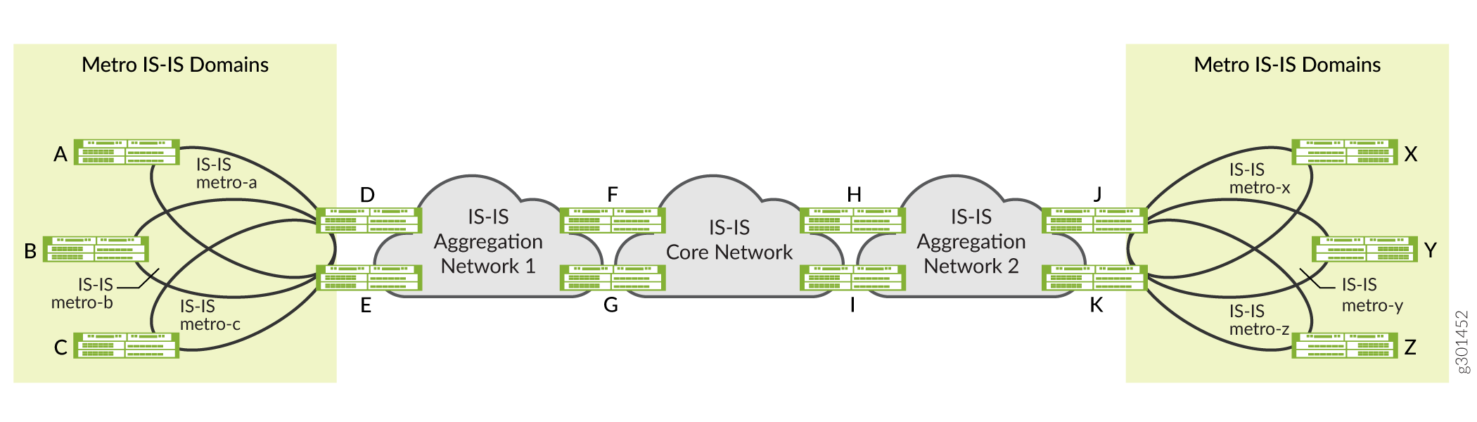
図 1 は、ルーターで IS-IS の複数の IGP インスタンスを設定するいくつかの利点を示しています。例えば、ルーターFは2つの独立したIS-ISインスタンスに参加しています。ルーターFは、IS-ISアグリゲーションネットワーク-1とIS-ISコアネットワークを2つの独立したIGPドメインとして扱うと同時に、これらのドメイン間のルートを再分配します。ネットワーク事業者は、この柔軟性を利用して IS-IS ドメインの階層を構築できます。
図1 は、IS-ISの複数のIGPインスタンスを使用して、メトロネットワークを独立したIS-ISフラッディングドメインに分離する方法も示しています。この例では、ルーター D と E は、IS-IS メトロ a、IS-IS メトロ b、IS-IS メトロ c ネットワーク、および IS-IS アグリゲーション ネットワーク 1 に参加しています。ルーターDとEは、異なるIS-ISドメインにIS-ISアドバタイズをフラッディングしません。代わりに、異なる IS-IS ドメイン間で特定のルートを再分配するため、よりスケーラブルなメトロ導入が可能になります。
マルチインスタンス IS-IS の概要
ルーター上で、IS-ISの複数の独立したIGPインスタンスを同時に設定して実行できます。これらのインスタンスはデフォルトのルーティングインスタンスに関連付けられ、デフォルトのルーティングテーブルにルートをインストールします。各IS-ISインスタンスは、標準のJunos OSルーティングポリシー設定を使用して、他のIS-ISインスタンスによってルーティングテーブルにインストールされたルートをエクスポートすることもできます。デフォルトでは、異なる IS-IS インスタンスによってインストールされたルートは、同じルート優先度を持ちます。
Junos OSは、IS-ISの複数のIGPインスタンスで同じ論理インターフェイスを設定することをサポートしていません。
ほとんどの導入シナリオでは、ルーター上の 1 つの IS-IS インスタンスのみが、特定のプレフィックスのルートをインストールします。そのため、複数のIS-ISインスタンスに対して異なるルート設定を設定する必要はありません。ただし、複数の IS-IS インスタンスがルーティングテーブル内の同じプレフィックスのルートをインストールする特定の導入シナリオでは、他の IS-IS インスタンスによってインストールされたルートに対して異なるルート優先値を設定できます。これにより、ルーティングテーブルは最適なルート優先度を持つルートを選択し、それらのルートを転送テーブルにインストールできます。
複数の IS-IS インスタンス機能は、階層型導入と並列導入の両方で使用できます。階層型導入の場合、異なる IGP インスタンスに参加するルーターのグループ間には明確に定義された境界があります。並列導入では、異なるIGPインスタンス(通常は2つまたは3つ以下)がルーターのグループ全体にまたがります。また、階層型デプロイメント内の一部のドメインでIGPインスタンスを並行して実行して、混合デプロイメントを行うこともできます。
[edit protocols]階層レベルでisis-instance設定ステートメントを含めることで、IS-ISの複数の独立したIGPインスタンスを設定することができます。[edit protocols isis-instance igp-instance-name] 階層レベルで使用する設定ステートメントは、[edit protocols isis] 階層レベルで使用可能なものと同じです。
isis-instance設定ステートメントは、[edit routing-instances routing-instance-name protocols]階層レベルではサポートされていません。
[edit protocols]階層レベルでospf-instance設定ステートメントを含めることで、OSPFv2の複数の独立したIGPインスタンスを設定することができます。[edit protocols ospf-instance igp-instance-name] 階層レベルで使用する設定ステートメントは、[edit protocols ospf] 階層レベルで使用可能なものと同じです。
ospf-instance設定ステートメントは、[edit routing-instances routing-instance-name protocols]階層レベルではサポートされていません。
ルーター上のセグメントルーティング(SR)を使用して、OSPFv2の複数の独立した内部ゲートウェイプロトコル(IGP)インスタンスを設定して実行できます。2つ以上のOSPFインスタンスを作成し、各インスタンスにSR-MPLSを適用できます。OSPFの複数のインスタンスは、異なるプレフィックスセグメント識別子(プレフィックスSID)をアドバタイズできます。他のインスタンスでは、ルーティングの決定にこれらのSIDを使用できます。
マルチインスタンスOSPFとSRを組み合わせることで、特に大規模で複雑なネットワークにおいて、ネットワークの柔軟性、拡張性、トラフィックエンジニアリングの制御が強化されます。
例:メトロフラッディングドメインにおける独立したIS-ISインスタンスの設定
この例では、IS-ISの複数のIGPインスタンスを実行する独立したメトロフラッディングドメインを設定する方法を学習します。
概要
この例では、メトロフラッディングドメインでIS-ISの複数の独立したIGPインスタンスを設定して実行する方法を示します。
トポロジー
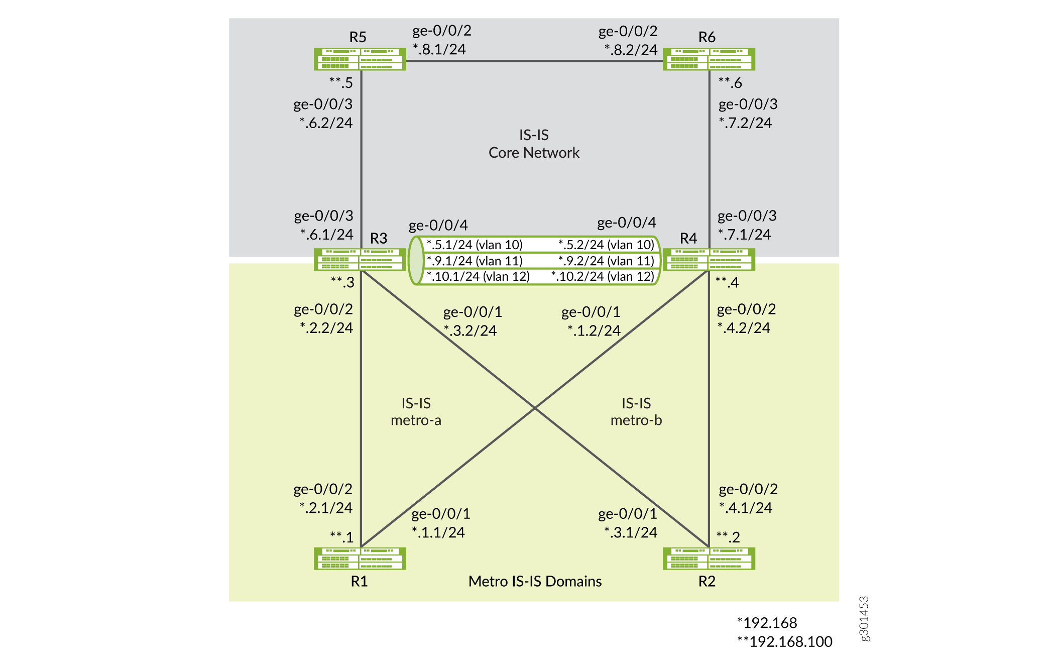
図2 は、IS-ISの独立したIGPインスタンスを実行しているメトロフラッディングドメイン(メトロ-aおよびメトロ-b)の例を示しています。トポロジーでは、ルーターR3とR4は、メトロIS-ISドメイン(IS-ISメトロaおよびIS-ISメトロ-b)とIS-ISコアネットワークドメインに参加しています。ルーターR3およびR4は、異なるIS-ISドメインにIS-ISアドバタイズをフラッディングしません。代わりに、異なる IS-IS ドメイン間で特定のルートを再分配するため、よりスケーラブルなメトロ導入が可能になります。
要件
この例では、以下のハードウェアおよびソフトウェアコンポーネントを使用しています。
- MXシリーズルーター
- すべてのデバイスで実行されている Junos OS リリース 21.1R1 以降
ネットワークサービスモードを拡張IPとして設定する必要があります。拡張IP設定により、ルーターが拡張モード機能を確実に使用できるようになります。
[edit]
user@CE1#set chassis network-services enhanced-ip
enhanced-ipステートメントを設定し、設定をコミットすると、以下の警告メッセージが表示され、ルーター再起動するように促します。
'chassis'
WARNING: Chassis configuration for network services has been changed. A system reboot is mandatory. Please reboot the system NOW. Continuing without a reboot might result in unexpected system behavior.
commit complete
再起動すると、ルーターにFPCが立ち上がります。
[ show chassis network-servicesを参照してください。]
設定
ルーター上で IS-IS の複数の IGP インスタンスを設定して実行するには、以下のタスクを実行します。
CLIクイックコンフィグレーション
この例をすばやく設定するには、以下のコマンドをコピーしてテキストファイルに貼り付け、改行を削除して、ネットワーク構成に合わせて必要な詳細を変更し、[edit]階層レベルのCLIにコマンドをコピー&ペーストします。
デバイスR1
set interfaces ge-0/0/1 description R1-to-R4
set interfaces ge-0/0/1 unit 0 family inet address 192.168.1.1/24
set interfaces ge-0/0/1 unit 0 family iso
set interfaces ge-0/0/2 description R1-to-R3
set interfaces ge-0/0/2 unit 0 family inet address 192.168.2.1/24
set interfaces ge-0/0/2 unit 0 family iso
set interfaces lo0 unit 0 family inet address 192.168.100.1/32
set interfaces lo0 unit 0 family iso address 49.0002.0192.0168.0001.00
set protocols isis interface ge-0/0/1.0 level 2 metric 100
set protocols isis interface ge-0/0/1.0 level 1 disable
set protocols isis interface ge-0/0/1.0 point-to-point
set protocols isis interface ge-0/0/2.0 level 1 disable
set protocols isis interface ge-0/0/2.0 level 2 metric 100
set protocols isis interface ge-0/0/2.0 point-to-point
set protocols isis interface lo0.0 passive
set routing-options router-id 192.168.100.1
デバイスR2
set interfaces ge-0/0/1 description R2-to-R3
set interfaces ge-0/0/1 unit 0 family inet address 192.168.3.1/24
set interfaces ge-0/0/1 unit 0 family iso
set interfaces ge-0/0/2 description R2-to-R4
set interfaces ge-0/0/2 unit 0 family inet address 192.168.4.1/24
set interfaces ge-0/0/2 unit 0 family iso
set interfaces lo0 unit 0 family inet address 192.168.100.2/32
set interfaces lo0 unit 0 family iso address 49.0002.0192.0168.0002.00
set protocols isis interface ge-0/0/1.0 level 1 disable
set protocols isis interface ge-0/0/1.0 level 2 metric 100
set protocols isis interface ge-0/0/1.0 point-to-point
set protocols isis interface ge-0/0/2.0 level 1 disable
set protocols isis interface ge-0/0/2.0 level 2 metric 100
set protocols isis interface ge-0/0/2.0 point-to-point
set protocols isis interface lo0.0 passive
set routing-options router-id 192.168.100.2
デバイスR3
set interfaces ge-0/0/1 description R3-to-R2
set interfaces ge-0/0/1 unit 0 family inet address 192.168.3.2/24
set interfaces ge-0/0/1 unit 0 family iso
set interfaces ge-0/0/2 description R3-to-R1
set interfaces ge-0/0/2 unit 0 family inet address 192.168.2.2/24
set interfaces ge-0/0/2 unit 0 family iso
set interfaces ge-0/0/3 description R3-to-R5
set interfaces ge-0/0/3 unit 0 family inet address 192.168.6.1/24
set interfaces ge-0/0/3 unit 0 family iso
set interfaces ge-0/0/4 description R3-to-R4
set interfaces ge-0/0/4 vlan-tagging
set interfaces ge-0/0/4 unit 0 vlan-id 10
set interfaces ge-0/0/4 unit 0 family inet address 192.168.5.1/24
set interfaces ge-0/0/4 unit 0 family iso
set interfaces ge-0/0/4 unit 1 vlan-id 11
set interfaces ge-0/0/4 unit 1 family inet address 192.168.9.1/24
set interfaces ge-0/0/4 unit 1 family iso
set interfaces ge-0/0/4 unit 2 vlan-id 12
set interfaces ge-0/0/4 unit 2 family inet address 192.168.10.1/24
set interfaces ge-0/0/4 unit 2 family iso
set interfaces lo0 unit 0 family inet address 192.168.100.3/32
set interfaces lo0 unit 0 family iso address 49.0002.0192.0168.0003.00
set policy-options policy-statement export-direct-loopback from protocol direct
set policy-options policy-statement export-direct-loopback from route-filter 192.168.100.3/32 exact
set policy-options policy-statement export-direct-loopback then accept
set policy-options policy-statement export-isis from protocol isis
set policy-options policy-statement export-isis from level 2
set policy-options policy-statement export-isis from route-filter 192.168.100.0/24 longer
set policy-options policy-statement export-isis then accept
set policy-options policy-statement export-isis-metro-a from igp-instance metro-a
set policy-options policy-statement export-isis-metro-a from protocol isis
set policy-options policy-statement export-isis-metro-a from level 2
set policy-options policy-statement export-isis-metro-a from route-filter 192.168.100.0/24 longer
set policy-options policy-statement export-isis-metro-a then accept
set policy-options policy-statement export-isis-metro-b from igp-instance metro-b
set policy-options policy-statement export-isis-metro-b from protocol isis
set policy-options policy-statement export-isis-metro-b from level 2
set policy-options policy-statement export-isis-metro-b from route-filter 192.168.100.0/24 longer
set policy-options policy-statement export-isis-metro-b then accept
set protocols isis interface ge-0/0/3.0 level 1 disable
set protocols isis interface ge-0/0/3.0 level 2 metric 100
set protocols isis interface ge-0/0/3.0 point-to-point
set protocols isis interface ge-0/0/4.0 level 1 disable
set protocols isis interface ge-0/0/4.0 level 2 metric 100
set protocols isis interface ge-0/0/4.0 point-to-point
set protocols isis interface lo0.0 passive
set protocols isis export export-isis-metro-a
set protocols isis export export-isis-metro-b
set protocols isis-instance metro-b interface ge-0/0/1.0 level 1 disable
set protocols isis-instance metro-b interface ge-0/0/1.0 level 2 metric 100
set protocols isis-instance metro-b interface ge-0/0/1.0 point-to-point
set protocols isis-instance metro-b interface ge-0/0/4.2 level 1 disable
set protocols isis-instance metro-b interface ge-0/0/4.2 level 2 metric 100
set protocols isis-instance metro-b interface ge-0/0/4.2 point-to-point
set protocols isis-instance metro-b export export-isis
set protocols isis-instance metro-b export export-direct-loopback
set protocols isis-instance metro-b export export-isis-metro-a
set protocols isis-instance metro-a interface ge-0/0/2.0 level 1 disable
set protocols isis-instance metro-a interface ge-0/0/2.0 level 2 metric 100
set protocols isis-instance metro-a interface ge-0/0/2.0 point-to-point
set protocols isis-instance metro-a interface ge-0/0/4.1 level 1 disable
set protocols isis-instance metro-a interface ge-0/0/4.1 level 2 metric 100
set protocols isis-instance metro-a interface ge-0/0/4.1 point-to-point
set protocols isis-instance metro-a export export-isis
set protocols isis-instance metro-a export export-direct-loopback
set protocols isis-instance metro-a export export-isis-metro-b
set routing-options router-id 192.168.100.3
デバイスR4
set interfaces ge-0/0/1 description R4-to-R1
set interfaces ge-0/0/1 unit 0 family inet address 192.168.1.2/24
set interfaces ge-0/0/1 unit 0 family iso
set interfaces ge-0/0/2 description R4-to-R2
set interfaces ge-0/0/2 unit 0 family inet address 192.168.4.2/24
set interfaces ge-0/0/2 unit 0 family iso
set interfaces ge-0/0/3 description R4-to-R6
set interfaces ge-0/0/3 unit 0 family inet address 192.168.7.1/24
set interfaces ge-0/0/3 unit 0 family iso
set interfaces ge-0/0/4 description R4-to-R3
set interfaces ge-0/0/4 vlan-tagging
set interfaces ge-0/0/4 unit 0 vlan-id 10
set interfaces ge-0/0/4 unit 0 family inet address 192.168.5.2/24
set interfaces ge-0/0/4 unit 0 family iso
set interfaces ge-0/0/4 unit 1 vlan-id 11
set interfaces ge-0/0/4 unit 1 family inet address 192.168.9.2/24
set interfaces ge-0/0/4 unit 1 family iso
set interfaces ge-0/0/4 unit 2 vlan-id 12
set interfaces ge-0/0/4 unit 2 family inet address 192.168.10.2/24
set interfaces ge-0/0/4 unit 2 family iso
set interfaces lo0 unit 0 family inet address 192.168.100.4/32
set interfaces lo0 unit 0 family iso address 49.0002.0192.0168.0004.00
set policy-options policy-statement export-direct-loopback from protocol direct
set policy-options policy-statement export-direct-loopback from route-filter 192.168.100.4/32 exact
set policy-options policy-statement export-direct-loopback then accept
set policy-options policy-statement export-isis from protocol isis
set policy-options policy-statement export-isis from level 2
set policy-options policy-statement export-isis from route-filter 192.168.100.0/24 longer
set policy-options policy-statement export-isis then accept
set policy-options policy-statement export-isis-metro-a from igp-instance metro-a
set policy-options policy-statement export-isis-metro-a from protocol isis
set policy-options policy-statement export-isis-metro-a from level 2
set policy-options policy-statement export-isis-metro-a from route-filter 192.168.100.0/24 longer
set policy-options policy-statement export-isis-metro-a then accept
set policy-options policy-statement export-isis-metro-b from igp-instance metro-b
set policy-options policy-statement export-isis-metro-b from protocol isis
set policy-options policy-statement export-isis-metro-b from level 2
set policy-options policy-statement export-isis-metro-b from route-filter 192.168.100.0/24 longer
set policy-options policy-statement export-isis-metro-b then accept
set protocols isis interface ge-0/0/3.0 level 1 disable
set protocols isis interface ge-0/0/3.0 level 2 metric 100
set protocols isis interface ge-0/0/3.0 point-to-point
set protocols isis interface ge-0/0/4.0 level 1 disable
set protocols isis interface ge-0/0/4.0 level 2 metric 100
set protocols isis interface ge-0/0/4.0 point-to-point
set protocols isis interface lo0.0 passive
set protocols isis export export-isis-metro-a
set protocols isis export export-isis-metro-b
set protocols isis-instance metro-a interface ge-0/0/1.0 level 1 disable
set protocols isis-instance metro-a interface ge-0/0/1.0 level 2 metric 100
set protocols isis-instance metro-a interface ge-0/0/1.0 point-to-point
set protocols isis-instance metro-a interface ge-0/0/4.1 level 1 disable
set protocols isis-instance metro-a interface ge-0/0/4.1 level 2 metric 100
set protocols isis-instance metro-a interface ge-0/0/4.1 point-to-point
set protocols isis-instance metro-a export export-isis
set protocols isis-instance metro-a export export-direct-loopback
set protocols isis-instance metro-a export export-isis-metro-b
set protocols isis-instance metro-b interface ge-0/0/2.0 level 1 disable
set protocols isis-instance metro-b interface ge-0/0/2.0 level 2 metric 100
set protocols isis-instance metro-b interface ge-0/0/2.0 point-to-point
set protocols isis-instance metro-b interface ge-0/0/4.2 level 1 disable
set protocols isis-instance metro-b interface ge-0/0/4.2 level 2 metric 100
set protocols isis-instance metro-b interface ge-0/0/4.2 point-to-point
set protocols isis-instance metro-b export export-isis
set protocols isis-instance metro-b export export-direct-loopback
set protocols isis-instance metro-b export export-isis-metro-a
set routing-options router-id 192.168.100.4
デバイスR5
set interfaces ge-0/0/2 description R5-to-R6
set interfaces ge-0/0/2 unit 0 family inet address 192.168.8.1/24
set interfaces ge-0/0/2 unit 0 family iso
set interfaces ge-0/0/3 description R5-to-R3
set interfaces ge-0/0/3 unit 0 family inet address 192.168.6.2/24
set interfaces ge-0/0/3 unit 0 family iso
set interfaces lo0 unit 0 family inet address 192.168.100.5/32
set interfaces lo0 unit 0 family iso address 49.0002.0192.0168.0005.00
set protocols isis interface ge-0/0/2.0 level 1 disable
set protocols isis interface ge-0/0/2.0 level 2 metric 100
set protocols isis interface ge-0/0/2.0 point-to-point
set protocols isis interface ge-0/0/3.0 level 1 disable
set protocols isis interface ge-0/0/3.0 level 2 metric 100
set protocols isis interface ge-0/0/3.0 point-to-point
set protocols isis interface lo0.0 passive
set routing-options router-id 192.168.100.5
デバイスR6
set interfaces ge-0/0/2 description R6-to-R5
set interfaces ge-0/0/2 unit 0 family inet address 192.168.8.2/24
set interfaces ge-0/0/2 unit 0 family iso
set interfaces ge-0/0/3 description R6-to-R4
set interfaces ge-0/0/3 unit 0 family inet address 192.168.7.2/24
set interfaces ge-0/0/3 unit 0 family iso
set interfaces lo0 unit 0 family inet address 192.168.100.6/32
set interfaces lo0 unit 0 family iso address 49.0002.0192.0168.0006.00
set protocols isis interface ge-0/0/2.0 level 1 disable
set protocols isis interface ge-0/0/2.0 level 2 metric 100
set protocols isis interface ge-0/0/2.0 point-to-point
set protocols isis interface ge-0/0/3.0 level 1 disable
set protocols isis interface ge-0/0/3.0 level 2 metric 100
set protocols isis interface ge-0/0/3.0 point-to-point
set protocols isis interface lo0.0 passive
set routing-options router-id 192.168.100.6
R1の設定
ステップバイステップの手順
次の例では、設定階層のさまざまなレベルに移動する必要があります。CLIのナビゲーションについては、『CLIユーザーガイド』の「設定モードでのCLIエディターの使用」を参照してください。
この例の手順を使用して、R2、R5、R6ルーターを設定することもできます。これらのルーターで使用されているインターフェイスID、IPアドレス、およびループバックアドレスを理解するには、 CLIクイックコンフィグレーション と 図2 を参照してください。
R1を設定するには:
-
IP(
inet)およびISOファミリーのサポートを有効にするようにインターフェイスを設定します。user@R1# set interfaces ge-0/0/1 description R1-to-R4 user@R1# set interfaces ge-0/0/1 unit 0 family inet address 192.168.1.1/24 user@R1# set interfaces ge-0/0/1 unit 0 family iso user@R1# set interfaces ge-0/0/2 description R1-to-R3 user@R1# set interfaces ge-0/0/2 unit 0 family inet address 192.168.2.1/24 user@R1# set interfaces ge-0/0/2 unit 0 family iso
-
ループバックインターフェイスを作成し、IPアドレスとNETアドレスを設定します。
user@R1# set interfaces lo0 unit 0 family inet address 192.168.100.1/32
user@R1# set interfaces lo0 unit 0 family iso address 49.0002.0192.0168.0001.00
-
ドメイン内のルーターを特定するためのルーティングオプションを設定します。
user@R1# set routing-options router-id 192.168.100.1
-
インターフェイスで IS-IS を有効にします。
user@R1# set protocols isis interface ge-0/0/1.0 level 2 metric 100
user@R1# set protocols isis interface ge-0/0/1.0 level 1 disable
user@R1# set protocols isis interface ge-0/0/1.0 point-to-point
user@R1# set protocols isis interface ge-0/0/2.0 level 1 disable
user@R1# set protocols isis interface ge-0/0/2.0 level 2 metric 100
user@R1# set protocols isis interface ge-0/0/2.0 point-to-point
user@R1# set protocols isis interface lo0.0 passive
結果
設定モードから、 show interfaces、 show routing-options、 show protocols コマンドを入力して設定を確認します。出力に意図した設定が表示されない場合は、この例の手順を繰り返して設定を修正します。
interfaces {
    ge-0/0/1 {
        description R1-to-R4;
        unit 0 {
            family inet {
                address 192.168.1.1/24;
            }
            family iso;
        }
    }
    ge-0/0/2 {
        description R1-to-R3;
        unit 0 {
            family inet {
                address 192.168.2.1/24;
            }
            family iso;
        }
    }
    lo0 {
        unit 0 {
            family inet {
                address 192.168.100.1/32;
            }
            family iso {
                address 49.0002.0192.0168.0001.00;
            }
        }
    }
}
protocols {
    isis {
        interface ge-0/0/1.0 {
            level 2 metric 100;
            level 1 disable;
            point-to-point;
        }
        interface ge-0/0/2.0 {
            level 1 disable;
            level 2 metric 100;
            point-to-point;
        }
        interface lo0.0 {
            passive;
        }
    }
}
routing-options {
    router-id 192.168.100.1;
}
R3の設定
ステップバイステップの手順
次の例では、設定階層のさまざまなレベルに移動する必要があります。CLIのナビゲーションについては、『CLIユーザーガイド』の「設定モードでのCLIエディターの使用」を参照してください。
この例の手順を使用して、R4 ルーターを設定することもできます。ルーターで使用されるインターフェイスID、IPアドレス、およびループバックアドレスを理解するには、 CLIクイックコンフィギュ レーションと 図2 を参照してください。
R3を設定するには:
-
R1、R2、R5 に接続するインターフェイスを設定して、IP および ISO ファミリーのサポートを有効にします。
user@R3# set interfaces ge-0/0/1 description R3-to-R2
user@R3# set interfaces ge-0/0/1 unit 0 family inet address 192.168.3.2/24
user@R3# set interfaces ge-0/0/1 unit 0 family iso
user@R3# set interfaces ge-0/0/2 description R3-to-R1
user@R3# set interfaces ge-0/0/2 unit 0 family inet address 192.168.2.2/24
user@R3# set interfaces ge-0/0/2 unit 0 family iso
user@R3# set interfaces ge-0/0/3 description R3-to-R5
user@R3# set interfaces ge-0/0/3 unit 0 family inet address 192.168.6.1/24
user@R3# set interfaces ge-0/0/3 unit 0 family iso
-
R3とR4を接続する3つのサブインターフェイス(論理インターフェイス)を設定します(1つのIS-IS標準インスタンスと2つのIS-ISメトロインスタンス(IS-ISメトロ-aおよびIS-ISメトロ-b))。
注:標準IS-ISインスタンスとは、[
edit protocols isis]階層レベルで設定されたIS-IS IGPインスタンスを指します。user@R3# set interfaces ge-0/0/4 description R3-to-R4 user@R3# set interfaces ge-0/0/4 vlan-tagging user@R3# set interfaces ge-0/0/4 unit 0 vlan-id 10 user@R3# set interfaces ge-0/0/4 unit 0 family inet address 192.168.5.1/24 user@R3# set interfaces ge-0/0/4 unit 0 family iso user@R3# set interfaces ge-0/0/4 unit 1 vlan-id 11 user@R3# set interfaces ge-0/0/4 unit 1 family inet address 192.168.9.1/24 user@R3# set interfaces ge-0/0/4 unit 1 family iso user@R3# set interfaces ge-0/0/4 unit 2 vlan-id 12 user@R3# set interfaces ge-0/0/4 unit 2 family inet address 192.168.10.1/24 user@R3# set interfaces ge-0/0/4 unit 2 family iso
-
ループバックインターフェイスを作成し、IPアドレスとNETアドレスを設定します。
user@R3# set interfaces lo0 unit 0 family inet address 192.168.100.3/32
user@R3# set interfaces lo0 unit 0 family iso address 49.0002.0192.0168.0003.00
-
IS-ISメトロインスタンス(IS-ISメトロAとIS-ISメトロB)とIS-ISスタンダードインスタンス(コアネットワーク)ルーターのループバックアドレスを再分配するポリシーを設定し、必要に応じてルートをIS-ISドメインに分散できるようにします。
-
R3のループバックアドレスを配布するためのポリシーを設定します。
user@R3# set policy-options policy-statement export-direct-loopback from protocol direct
user@R3# set policy-options policy-statement export-direct-loopback from route-filter 192.168.100.3/32 exact
user@R3# set policy-options policy-statement export-direct-loopback then accept
-
R5およびR6ルーター(標準IS-ISインスタンス)のループバックアドレスを分散するためのポリシーを設定します。
user@R3# set policy-options policy-statement export-isis from protocol isis
user@R3# set policy-options policy-statement export-isis from level 2
user@R3# set policy-options policy-statement export-isis from route-filter 192.168.100.0/24 longer
user@R3# set policy-options policy-statement export-isis then accept
-
R1(IS-IS metro-aインスタンス)のループバックアドレスを分散するためのポリシーを設定します。
user@R3# set policy-options policy-statement export-isis-metro-a from igp-instance metro-a
user@R3# set policy-options policy-statement export-isis-metro-a from protocol isis
user@R3# set policy-options policy-statement export-isis-metro-a from level 2
user@R3# set policy-options policy-statement export-isis-metro-a from route-filter 192.168.100.0/24 longer
user@R3# set policy-options policy-statement export-isis-metro-a then accept
-
R2(IS-IS metro-bインスタンス)のループバックアドレスを分散するためのポリシーを設定します。
user@R3# set policy-options policy-statement export-isis-metro-b from igp-instance metro-b
user@R3# set policy-options policy-statement export-isis-metro-b from protocol isis
user@R3# set policy-options policy-statement export-isis-metro-b from level 2
user@R3# set policy-options policy-statement export-isis-metro-b from route-filter 192.168.100.0/24 longer
user@R3# set policy-options policy-statement export-isis-metro-b then accept
-
-
標準インスタンスインターフェイス(R3からR5に接続)とサブインターフェイス(R3からR4に接続)でIS-ISを有効にします。
user@R3# set protocols isis interface ge-0/0/3.0 level 1 disable
user@R3# set protocols isis interface ge-0/0/3.0 level 2 metric 100
user@R3# set protocols isis interface ge-0/0/3.0 point-to-point
user@R3# set protocols isis interface ge-0/0/4.0 level 1 disable
user@R3# set protocols isis interface ge-0/0/4.0 level 2 metric 100
user@R3# set protocols isis interface ge-0/0/4.0 point-to-point
user@R3# set protocols isis interface lo0.0 passive
-
IS-IS metro-aおよびIS-IS metro-bインスタンスからIS-IS標準インスタンスにループバックアドレスをエクスポートするようにIS-ISを設定します。この設定では、メトロドメイン全体にフラッディングするのではなく、特定のルートを分散します。
user@R3# set protocols isis export export-isis-metro-a
user@R3# set protocols isis export export-isis-metro-b
-
IS-IS メトロ b インスタンス インターフェイス(R3 から R2 に接続)とサブインターフェイス(R3 から R4)で IS-IS を有効にします。
user@R3# set protocols isis-instance metro-b interface ge-0/0/1.0 level 1 disable
user@R3# set protocols isis-instance metro-b interface ge-0/0/1.0 level 2 metric 100
user@R3# set protocols isis-instance metro-b interface ge-0/0/1.0 point-to-point
user@R3# set protocols isis-instance metro-b interface ge-0/0/4.2 level 1 disable
user@R3# set protocols isis-instance metro-b interface ge-0/0/4.2 level 2 metric 100
user@R3# set protocols isis-instance metro-b interface ge-0/0/4.2 point-to-point
-
IS-ISメトロAおよび標準IS-ISインスタンスのループバックアドレスをIS-ISメトロBインスタンスにエクスポートするようにIS-ISを設定します。この設定では、標準のIS-ISインスタンスやメトロ-aドメインインスタンス全体をフラッディングするのではなく、特定のルートを分散します。
user@R3# set protocols isis-instance metro-b export export-isis
user@R3# set protocols isis-instance metro-b export export-direct-loopback
user@R3# set protocols isis-instance metro-b export export-isis-metro-a
-
IS-IS メトロ a インスタンス インターフェイス(R3 から R1 に接続)とサブインターフェイス(R3 から R4)で IS-IS を有効にします。
user@R3# set protocols isis-instance metro-a interface ge-0/0/2.0 level 1 disable
user@R3# set protocols isis-instance metro-a interface ge-0/0/2.0 level 2 metric 100
user@R3# set protocols isis-instance metro-a interface ge-0/0/2.0 point-to-point
user@R3# set protocols isis-instance metro-a interface ge-0/0/4.1 level 1 disable
user@R3# set protocols isis-instance metro-a interface ge-0/0/4.1 level 2 metric 100
user@R3# set protocols isis-instance metro-a interface ge-0/0/4.1 point-to-point
-
IS-ISを設定して、IS-IS metro-bおよびstandard IS-ISインスタンスのループバックアドレスをIS-IS metro-aインスタンスにエクスポートします。この設定では、標準のIS-ISインスタンスやメトロ-bドメインインスタンス全体をフラッディングするのではなく、特定のルートを分散します。
user@R3# set protocols isis-instance metro-a export export-isis
user@R3# set protocols isis-instance metro-a export export-direct-loopback
user@R3# set protocols isis-instance metro-a export export-isis-metro-b
-
ドメイン内のルーターを特定するためのルーティングオプションを設定します。
user@R3# set routing-options router-id 192.168.100.3
結果
設定モードから、 show interfaces、 show routing-options、 show protocols コマンドを入力して設定を確認します。出力に意図した設定が表示されない場合は、この例の手順を繰り返して設定を修正します。
interfaces {
    ge-0/0/1 {
        description R3-to-R2;
        unit 0 {
            family inet {
                address 192.168.3.2/24;
            }
            family iso;
        }
    }
    ge-0/0/2 {
        description R3-to-R1;
        unit 0 {
            family inet {
                address 192.168.2.2/24;
            }
            family iso;
        }
    }
    ge-0/0/3 {
        description R3-to-R5;
        unit 0 {
            family inet {
                address 192.168.6.1/24;
            }
            family iso;
        }
    }
    ge-0/0/4 {
        description R3-to-R4;
        vlan-tagging;
        unit 0 {
            vlan-id 10;
            family inet {
                address 192.168.5.1/24;
            }
            family iso;
        }
        unit 1 {
            vlan-id 11;
            family inet {
                address 192.168.9.1/24;
            }
            family iso;
        }
        unit 2 {
            vlan-id 12;
            family inet {
                address 192.168.10.1/24;
            }
            family iso;
        }
    }
    lo0 {
        unit 0 {
            family inet {
                address 192.168.100.3/32;
            }
            family iso {
                address 49.0002.0192.0168.0003.00;
            }
        }
    }
}
policy-options {
    policy-statement export-direct-loopback {
        from {
            protocol direct;
            route-filter 192.168.100.3/32 exact;
        }
        then accept;
    }
    policy-statement export-isis {
        from {
            protocol isis;
            level 2;
            route-filter 192.168.100.0/24 longer;
        }
        then accept;
    }
    policy-statement export-isis-metro-a {
        from {
            igp-instance metro-a;
            protocol isis;
            level 2;
            route-filter 192.168.100.0/24 longer;
        }
        then accept;
    }
    policy-statement export-isis-metro-b {
        from {
            igp-instance metro-b;
            protocol isis;
            level 2;
            route-filter 192.168.100.0/24 longer;
        }
        then accept;
    }
}
protocols {
    isis {
        interface ge-0/0/3.0 {
            level 1 disable;
            level 2 metric 100;
            point-to-point;
        }
        interface ge-0/0/4.0 {
            level 1 disable;
            level 2 metric 100;
            point-to-point;
        }
        interface lo0.0 {
            passive;
        }
        export [ export-isis-metro-a export-isis-metro-b ];
    }
    isis-instance metro-b {
        interface ge-0/0/1.0 {
            level 1 disable;
            level 2 metric 100;
            point-to-point;
        }
        interface ge-0/0/4.2 {
            level 1 disable;
            level 2 metric 100;
            point-to-point;
        }
        export [ export-isis export-direct-loopback export-isis-metro-a ];
    }
    isis-instance metro-a {
        interface ge-0/0/2.0 {
            level 1 disable;
            level 2 metric 100;
            point-to-point;
        }
        interface ge-0/0/4.1 {
            level 1 disable;
            level 2 metric 100;
            point-to-point;
        }
        export [ export-isis export-direct-loopback export-isis-metro-b ];
    }
}
routing-options {
    router-id 192.168.100.3;
}
検証
設定が正常に機能していることを確認するには、以下のタスクを実行します。
IS-IS アドバタイズメントの検証
目的
PDU パケットに関するデータを含む IS-IS リンクステートデータベース(LSDB)の IS-IS アドバタイズ エントリーを確認します。
アクション
動作モードから、 show isis database level 2 コマンドを実行します。
R3について
user@R3>show isis database level 2

IS-IS level 2 link-state database:
LSP ID                      Sequence Checksum Lifetime Attributes
R6.00-00                       0x75d   0x1ff7     1181 L1 L2
R5.00-00                       0x75b   0xffdc      741 L1 L2
R4.00-00                       0x780    0x4e1      552 L1 L2
R3.00-00                       0x7f0   0x8643      496 L1 L2
  4 LSPs
user@R3>show isis database level 2 igp-instance metro-a
IS-IS level 2 link-state database:
LSP ID                      Sequence Checksum Lifetime Attributes
R1.00-00                       0x136   0x46e5     1046 L1 L2
R4.00-00                       0x781   0xf65e      768 L1 L2
R3.00-00                       0x7f2   0x871b      764 L1 L2
  3 LSPs
user@R3>show isis database level 2 igp-instance metro-b
IS-IS level 2 link-state database:
LSP ID                      Sequence Checksum Lifetime Attributes
R2.00-00                       0x13a   0x7997     1013 L1 L2
R4.00-00                       0x781   0x86ba      771 L1 L2
R3.00-00                       0x7f2   0x1288      510 L1 L2
  3 LSPs
R1について
user@R1>show isis database level 2

IS-IS level 2 link-state database:
LSP ID                      Sequence Checksum Lifetime Attributes
R1.00-00                       0x136   0x46e5      851 L1 L2
R4.00-00                       0x781   0xf65e      571 L1 L2
R3.00-00                       0x7f2   0x871b      565 L1 L2
  3 LSPs
意味
R3のこの出力は、R3が標準のIS-ISインスタンスであるR4、R5、およびR6からのIS-ISアドバタイズメントを確認していることを示しています。R3 は、R1(メトロ a IS-IS)、R2(メトロ b IS-IS)、R4(メトロ a と IS-IS メトロ b の両方IS-IS)からのIS-ISアドバタイズも確認します。このように、R3 は、IS-IS メトロ a インスタンス、IS-IS メトロ b インスタンス、標準 IS-ISIS インスタンス(コア ネットワーク)の間で IS-IS ルートを再分配する共通ルーターであることがわかります。
R1の出力は、R1がR3とR4からのIS-ISアドバタイズのみを見ることを示しています。R1 は、R2 からの IS-IS アドバタイズメントを認識しません。したがって、IS-IS metro-aとIS-IS metro-bは別個のIS-ISフラッディングドメインであることがわかります。このプロパティを使用して、よりスケーラブルなネットワークを構築できます。
ルーティングテーブルの検証
目的
ルーティングテーブルのルートエントリーを検証します。
アクション
動作モードから、 show route table inet.0 route-destination address extensive コマンドを実行します。
R3について
user@R3>show route table inet.0 192.168.100.1 extensive

inet.0: 28 destinations, 28 routes (28 active, 0 holddown, 0 hidden)
192.168.100.1/32 (1 entry, 1 announced)
TSI:
KRT in-kernel 192.168.100.1/32 -> {192.168.2.1}
IS-IS level 1, LSP fragment 0
IS-IS level 2, LSP fragment 0
IS-IS level 1, LSP fragment 0
IS-IS level 2, LSP fragment 0
        *IS-IS  Preference: 18
                Level: 2
                Next hop type: Router, Next hop index: 601
                Address: 0xc5b21cc
                Next-hop reference count: 2
                Next hop: 192.168.2.1 via ge-0/0/2.0, selected
                Session Id: 0x140
                State: <Active Int>
                Age: 2d 18:10:36        Metric: 63
                Validation State: unverified
                ORR Generation-ID: 0
                Task: IS-IS-metro-a
                Announcement bits (3): 0-KRT 2-IS-IS 10-IS-IS-metro-b
                AS path: I
                Thread: junos-main
user@R3>show route table inet.0 192.168.100.2 extensive
inet.0: 28 destinations, 28 routes (28 active, 0 holddown, 0 hidden)
192.168.100.2/32 (1 entry, 1 announced)
TSI:
KRT in-kernel 192.168.100.2/32 -> {192.168.3.1}
IS-IS level 1, LSP fragment 0
IS-IS level 2, LSP fragment 0
IS-IS level 1, LSP fragment 0
IS-IS level 2, LSP fragment 0
        *IS-IS  Preference: 18
                Level: 2
                Next hop type: Router, Next hop index: 602
                Address: 0xc5b2234
                Next-hop reference count: 2
                Next hop: 192.168.3.1 via ge-0/0/1.0, selected
                Session Id: 0x141
                State: <Active Int>
                Age: 2d 18:18:48        Metric: 63
                Validation State: unverified
                ORR Generation-ID: 0
                Task: IS-IS-metro-b
                Announcement bits (3): 0-KRT 2-IS-IS 4-IS-IS-metro-a
                AS path: I
                Thread: junos-main
意味
出力は、R1のループバックアドレス(192.168.100.1)がIS-ISメトロ-aインスタンス(IS-IS-metro-a)にマッピングされ、R2のループバックアドレス(192.168.100.2)がR3で設定されたIS-ISメトロ-bインスタンス(IS-IS-metro-b)にマッピングされていることを示しています。
IS-ISルーティングテーブル内のルートの検証
目的
IS-IS ルーティングテーブル内のルートを検証します。
アクション
動作モードから、 show isis route コマンドを実行します。
R3について
user@R3>show isis route
IS-IS routing table             Current version: L1: 1885 L2: 1956
IPv4/IPv6 Routes
----------------
Prefix             L Version   Metric Type Interface       NH   Via                 Backup Score
192.168.7.0/24     2    1956      126 int  ge-0/0/4.0      IPV4 R4
192.168.8.0/24     2    1956      126 int  ge-0/0/3.0      IPV4 R5
192.168.100.4/32   2    1956       63 int  ge-0/0/4.0      IPV4 R4
192.168.100.5/32   2    1956       63 int  ge-0/0/3.0      IPV4 R5
192.168.100.6/32   2    1956      126 int  ge-0/0/3.0      IPV4 R5
                                           ge-0/0/4.0      IPV4 R4
user@R3>show isis route igp-instance metro-a
 IS-IS routing table             Current version: L1: 1889 L2: 1961
IPv4/IPv6 Routes
----------------
Prefix             L Version   Metric Type Interface       NH   Via                 Backup Score
192.168.1.0/24     2    1961      126 int  ge-0/0/4.1      IPV4 R4
                                           ge-0/0/2.0      IPV4 R1
192.168.100.1/32   2    1961       63 int  ge-0/0/2.0      IPV4 R1
user@R3>show isis route igp-instance metro-b
 IS-IS routing table             Current version: L1: 1892 L2: 1949
IPv4/IPv6 Routes
----------------
Prefix             L Version   Metric Type Interface       NH   Via                 Backup Score
192.168.4.0/24     2    1949      126 int  ge-0/0/4.2      IPV4 R4
                                           ge-0/0/1.0      IPV4 R2
192.168.100.2/32   2    1949       63 int  ge-0/0/1.0      IPV4 R2
R1について
user@R1>show isis route
IS-IS routing table             Current version: L1: 313 L2: 392
IPv4/IPv6 Routes
----------------
Prefix             L Version   Metric Type Interface       NH   Via                 Backup Score
192.168.9.0/24     2     392      126 int  ge-0/0/2.0      IPV4 R3
                                           ge-0/0/1.0      IPV4 R4
192.168.100.2/32   2     392      126 int  ge-0/0/2.0      IPV4 R3
                                           ge-0/0/1.0      IPV4 R4
192.168.100.3/32   2     392       73 int  ge-0/0/2.0      IPV4 R3
192.168.100.4/32   2     392       73 int  ge-0/0/1.0      IPV4 R4
192.168.100.5/32   2     392      126 int  ge-0/0/2.0      IPV4 R3
                                           ge-0/0/1.0      IPV4 R4
192.168.100.6/32   2     392      126 int  ge-0/0/2.0      IPV4 R3
                                           ge-0/0/1.0      IPV4 R4
意味
R3の出力は、R1、R2、R4、R5、およびR6のループバックアドレスとIS-ISインスタンスマッピング情報を示しています。
R1の出力は、R2、R3、R4、R5、およびR6のループバックアドレスを示しています。
IS-ISインターフェイスの検証
目的
IS-IS対応インターフェイスのステータス情報を確認します。
アクション
動作モードから、 show isis interface コマンドを実行します。
R3について
user@R3>show isis interface
IS-IS interface database:
Interface             L CirID Level 1 DR        Level 2 DR        L1/L2 Metric
ge-0/0/3.0            2   0x1 Disabled          Point to Point         10/100
ge-0/0/4.0            2   0x1 Disabled          Point to Point         10/100
lo0.0                 3   0x1 Passive           Passive                 0/0
user@R3>show isis interface igp-instance metro-a
IS-IS interface database:
Interface             L CirID Level 1 DR        Level 2 DR        L1/L2 Metric
ge-0/0/2.0            2   0x1 Disabled          Point to Point         10/100
ge-0/0/4.1            2   0x1 Disabled          Point to Point         10/100
user@R3>show isis interface igp-instance metro-b
IS-IS interface database:
Interface             L CirID Level 1 DR        Level 2 DR        L1/L2 Metric
ge-0/0/1.0            2   0x1 Disabled          Point to Point         10/100
ge-0/0/4.2            2   0x1 Disabled          Point to Point         10/100
R1について
user@R1>show isis interface
IS-IS interface database:
Interface             L CirID Level 1 DR        Level 2 DR        L1/L2 Metric
ge-0/0/1.0            2   0x1 Disabled          Point to Point         10/100
ge-0/0/2.0            2   0x1 Disabled          Point to Point         10/100
lo0.0                 3   0x1 Passive           Passive                 0/0
意味
出力は、異なるIS-ISインスタンスにマッピングされたインターフェイスを示しています。
例:セグメントルーティングでOSPFv2の複数の独立したインスタンスを設定する
この例では、セグメントルーティングを使用して、OSPFv2の複数のIGPインスタンスを設定します。
この例は、当社のコンテンツテストチームが検証し、更新しました。
| 読書時間 |
30分 |
| 設定時間 |
20分 |
前提条件の例
| ハードウェア要件 |
MXシリーズルーター3台。 |
| ソフトウェア要件 |
すべてのデバイスで実行されている Junos OS リリース 24.4R1 以降。 |
始める前に
| 利点 |
セグメントルーティングを使用してOSPFv2の複数の独立したインスタンスを設定することで、特に大規模で複雑なネットワークにおいて、ネットワークの柔軟性、拡張性、トラフィックエンジニアリングの制御が強化されます。 |
| 詳細はこちら |
機能の概要
| 使用されたテクノロジー |
|
| 一次検証タスク |
|
トポロジーの概要
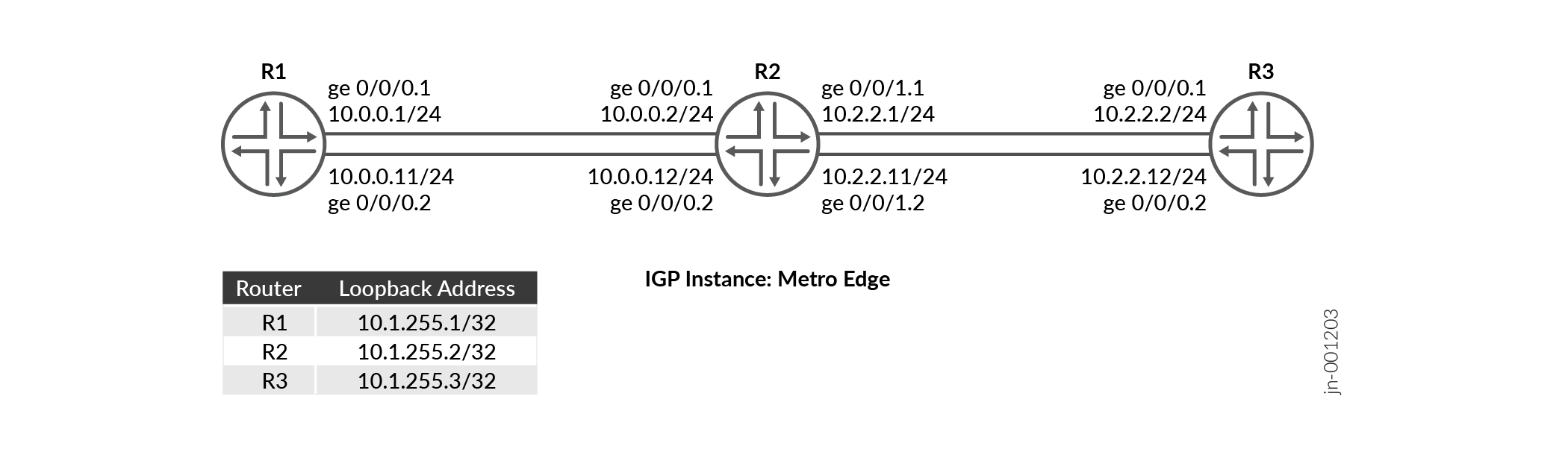
この設定例では、R1、R2、R3 の 3 つのデバイスを示しています。デバイスR1とデバイスR2の間、およびデバイスR2とデバイスR3の間に設定された2つのサブインターフェイスがあります。各デバイスは、セグメントルーティングを有効にした状態で複数のOSPFインスタンスを実行します。ネットワーク経由でパスを制御できるようにSR-MPLSを設定します。デバイスの2つのサブインターフェイスのそれぞれで実行されている metro-edge という名前のOSPFインスタンスがあります。
| ホスト名 |
役割 |
機能 |
|---|---|---|
| R1、R2、R3 |
デバイスのサブインターフェイスにはマルチインスタンス OSPF が設定されており、セグメント ルーティングが有効になっています。 |
デバイスは、OSPFマルチインスタンスに参加し、ルートをアドバタイズし、プレフィックスSIDを使用して他のデバイスにトラフィックを転送します。 |
トポロジー図
R2の設定手順
R2 の設定例の詳細については、次を参照してください。 付録 1:すべてのデバイスでコマンドを設定する
このセクションでは、この例の R2 デバイスの設定に必要な主な設定タスクに焦点を当てます。
-
デバイスインターフェイスの論理ユニットでホスト名、
enhanced-ipモード、IPv4アドレスなどの基本的なデバイス設定を構成します。IPアドレスでループバックインターフェイスを設定し、MPLSを有効にします。
ルーターIDと自律システム(AS)番号を設定して、同じASに属する一連のルーティングデバイス内でルーティング情報を伝送します。
VLANタグを有効にし、異なるVLAN IDを持つ両方のインターフェイスの論理ユニットを設定します。
各論理ユニットで MPLS を有効にします。各インターフェイスの論理ユニットの発信パケットに適用できるMPLSラベルの最大数を設定します。
パケットの負荷分散を行うポリシーを定義し、パケットごとのポリシーを適用してトラフィックのロードバランシングを有効にします。
正確なプレフィックスに基づいてルートを一致させるポリシーステートメントを設定し、一致したルートにセグメント識別子を割り当てます。
セグメントルーティングドメイン全体でラベルの予測可能性を高めるために、
edit protocol mpls階層レベルでMPLSトラフィックエンジニアリングセグメントルーティンググローバルブロック(SRGB)ラベル範囲を設定し、設定されたsrgbラベルからリンクにラベルを割り当てるためのラベル範囲MPLS設定します。[edit] set system host-name R2 set chassis network-services enhanced-ip set interfaces ge-0/0/0 unit 1 family inet address 10.0.0.2/24 set interfaces ge-0/0/0 unit 2 family inet address 10.0.0.12/24 set interfaces ge-0/0/1 unit 1 family inet address 10.2.2.1/24 set interfaces ge-0/0/1 unit 2 family inet address 10.2.2.11/24
[edit]
set interfaces lo0 unit 0 family inet address 10.1.255.2/32
set interfaces lo0 unit 0 family mpls
[edit]
set routing-options router-id 10.1.255.2
set routing-options autonomous-system 100
[edit]
set interfaces ge-0/0/0 vlan-tagging
set interfaces ge-0/0/0 unit 1 vlan-id 1
set interfaces ge-0/0/0 unit 2 vlan-id 2
set interfaces ge-0/0/1 vlan-tagging
set interfaces ge-0/0/1 unit 1 vlan-id 1
set interfaces ge-0/0/1 unit 2 vlan-id 2
[edit]
set interfaces ge-0/0/0 unit 1 family mpls maximum-labels 5
set interfaces ge-0/0/0 unit 2 family mpls maximum-labels 5
set interfaces ge-0/0/1 unit 1 family mpls maximum-labels 5
set interfaces ge-0/0/1 unit 2 family mpls maximum-labels 5
[edit]
set policy-options policy-statement pplb then load-balance per-packet
set policy-options policy-statement pplb then accept
set routing-options forwarding-table export pplb
[edit]
set policy-options policy-statement prefix-sid term 1 from route-filter 10.1.255.2/32 exact
set policy-options policy-statement prefix-sid term 1 then prefix-segment index 1001
set policy-options policy-statement prefix-sid term 1 then accept
[edit]
set protocols mpls traffic-engineering
set protocols mpls label-range srgb-label-range 800000 879999
set protocols mpls label-range static-label-range 60001 100000
set protocols mpls interface all
set protocols mpls interface fxp0.0 disable
サブインターフェイス(R2からR1、およびR2からR3への接続)で
ospf-instancemetro-edgeを設定します。[edit] set protocols ospf-instance metro-edge area 0.0.0.0 interface all
プレフィックスSIDを使用したセグメントルーティングを使用できるようにOSPF
metro-edgeインスタンスを有効にします。[edit] set protocols ospf-instance metro-edge source-packet-routing prefix-segment prefix-sid
- ノードセグメントのIPv4インデックス値を設定します。
[edit]
set protocols ospf-instance metro-edge source-packet-routing node-segment ipv4-index 1
OSPF
metro-edgeインスタンスのループバックアドレスをパッシブとして設定し、管理インターフェイス(fxp0.0)を無効にします。[edit] set protocols ospf-instance metro-edge area 0.0.0.0 interface lo0.0 passive set protocols ospf-instance metro-edge area 0.0.0.0 interface fxp0.0 disable
検証
| コマンド | 検証タスク |
|---|---|
| show route protocol ospf table inet.0 extensive |
|
| show ospf spring sid-database igp-instance igp-instance | OSPFインスタンスのOSPFセグメントルーティングデータベースを確認します。 |
| show ospf neighbor igp-instance igp-instance | 特定の OSPF インスタンスのネイバーを検証します。 |
| ospf データベース igp-instance を表示 igp-instance | IGPインスタンスに関連付けられたOSPFリンクステートデータベース(LSDB)内のOSPFアドバタイズエントリを確認します。 |
| show ospf interface igp-instance igp-instance | IGPインスタンスにマッピングされたインターフェイスを確認します。 |
| show ospf route igp-instance igp-instance | R1とR3のルートとOSPFインスタンスマッピング情報を確認します。 |
- ルーティングテーブルの検証
- OSPF アドバタイズメントの検証
- OSPFルーティングテーブル内のルートの検証
- OSPFセグメントルーティングデータベースの検証
- OSPFインターフェースの検証
- OSPFネイバーの検証
ルーティングテーブルの検証
目的
ルーティングテーブルのルートエントリーを検証します
アクション
動作モードから、 show route table inet.0 route-destination address extensive コマンドを実行します。
user@R2>show route protocol ospf table inet.0 10.1.255.1 extensive
inet.0: 19 destinations, 21 routes (19 active, 0 holddown, 0 hidden)
10.1.255.1/32 (1 entry, 1 announced)
TSI:
KRT in-kernel 10.1.255.1/32 -> {list:10.0.0.1, 10.0.0.11}
        *OSPF   Preference: 10/10
                Next hop type: Router, Next hop index: 0
                Address: 0x8b32234
                Next-hop reference count: 2, Next-hop session id: 0
                Kernel Table Id: 0
                Next hop: 10.0.0.1 via ge-0/0/0.1, selected
                Session Id: 0
                Next hop: 10.0.0.11 via ge-0/0/0.2
                Session Id: 0
                State: <Active Int>
                Local AS:   100
                Age: 1w4d 16:01:19      Metric: 1
                Validation State: unverified
                Area: 0.0.0.0
                Task: OSPF-metro-edge
                Announcement bits (1): 0-KRT
                AS path: I
                Thread: junos-main

user@R2>show route protocol ospf table inet.0 10.1.255.3 extensive
inet.0: 19 destinations, 21 routes (19 active, 0 holddown, 0 hidden)
10.1.255.3/32 (1 entry, 1 announced)
TSI:
KRT in-kernel 10.1.255.3/32 -> {list:10.2.2.2, 10.2.2.12}
        *OSPF   Preference: 10/10
                Next hop type: Router, Next hop index: 0
                Address: 0x8b316f4
                Next-hop reference count: 2, Next-hop session id: 0
                Kernel Table Id: 0
                Next hop: 10.2.2.2 via ge-0/0/1.1, selected
                Session Id: 0
                Next hop: 10.2.2.12 via ge-0/0/1.2
                Session Id: 0
                State: <Active Int>
                Local AS:   100
                Age: 1w4d 16:13:55      Metric: 1
                Validation State: unverified
                Area: 0.0.0.0
                Task: OSPF-metro-edge
                Announcement bits (1): 0-KRT
                AS path: I
                Thread: junos-main
意味
出力は、R1 のループバック アドレス(10.1.255.1)と R3 のループバック アドレス(10.1.255.2)が、R2 で設定された OSPF igp インスタンス メトロエッジ にマッピングされていることを示しています。
OSPF アドバタイズメントの検証
目的
IGPインスタンスに関連付けられたOSPFリンクステートデータベース(LSDB)内のOSPFアドバタイズエントリを確認します。
アクション
動作モードから、 show ospf database igp-instance igp-instance コマンドを実行します。
user@R2>show ospf database igp-instance metro-edge
    OSPF database, Area 0.0.0.0
Type       ID               Adv Rtr           Seq      Age  Opt  Cksum  Len
Router   10.1.255.1       10.1.255.1       0x80000013  1110  0x22 0xe6e9  72
Router  *10.1.255.2       10.1.255.2       0x80000015  1084  0x22 0x7be2  96
Router   10.1.255.3       10.1.255.3       0x80000013  1585  0x22 0x491   72
Network *10.0.0.2         10.1.255.2       0x80000010  2959  0x22 0x6791  32
Network *10.0.0.12        10.1.255.2       0x80000010  2209  0x22 0x3eb   32
Network  10.2.2.2         10.1.255.3       0x80000010  2085  0x22 0x4ba6  32
Network  10.2.2.12        10.1.255.3       0x80000010  1085  0x22 0xe601  32
OpaqArea 7.0.0.1          10.1.255.1       0x80000012   193  0x22 0x8c0   44
OpaqArea*7.0.0.1          10.1.255.2       0x80000012   511  0x22 0x2a9b  44
OpaqArea 7.0.0.1          10.1.255.3       0x80000012   585  0x22 0x4c76  44
OpaqArea 8.0.0.1          10.1.255.1       0x80000010  2610  0x22 0x4683  48
OpaqArea*8.0.0.1          10.1.255.2       0x80000010  2584  0x22 0xac01  52
OpaqArea 8.0.0.1          10.1.255.3       0x80000010  2584  0x22 0x7d06  52
OpaqArea 8.0.0.2          10.1.255.1       0x80000010  1860  0x22 0x4f55  48
OpaqArea*8.0.0.2          10.1.255.2       0x80000011   334  0x22 0xf393  52
OpaqArea 8.0.0.2          10.1.255.3       0x80000011    84  0x22 0xc498  52
OpaqArea*8.0.0.3          10.1.255.2       0x80000010  1834  0x22 0x445a  48
OpaqArea*8.0.0.4          10.1.255.2       0x80000010  1459  0x22 0x4d2c  48
意味
OSPFルーティングテーブル内のルートの検証
目的
OSPF ルーティングテーブル内のルートを検証します
アクション
動作モードから、 show ospf route コマンドを実行します。
user@R2>show ospf route igp-instance metro-edge
Topology default Route Table:

Prefix             Path  Route      NH       Metric NextHop       Nexthop
                   Type  Type       Type            Interface     Address/LSP
10.1.255.1         Intra Router     IP            1 ge-0/0/0.1    10.0.0.1
                                                    ge-0/0/0.2    10.0.0.11
10.1.255.3         Intra Router     IP            1 ge-0/0/1.1    10.2.2.2
                                                    ge-0/0/1.2    10.2.2.12
10.0.0.0/24        Intra Network    IP            1 ge-0/0/0.1
                                                    ge-0/0/0.2
10.1.255.1/32      Intra Network    IP            1 ge-0/0/0.1    10.0.0.1
                                                    ge-0/0/0.2    10.0.0.11
10.1.255.2/32      Intra Network    IP            0 lo0.0
10.1.255.3/32      Intra Network    IP            1 ge-0/0/1.1    10.2.2.2
                                                    ge-0/0/1.2    10.2.2.12
10.2.2.0/24        Intra Network    IP            1 ge-0/0/1.1
                                                    ge-0/0/1.2
299840             Intra Network    Mpls          0 ge-0/0/0.2    10.0.0.11
299840 (S=0)       Intra Network    Mpls          0 ge-0/0/0.2    10.0.0.11
299856             Intra Network    Mpls          0 ge-0/0/0.1    10.0.0.1
299856 (S=0)       Intra Network    Mpls          0 ge-0/0/0.1    10.0.0.1
299904             Intra Network    Mpls          0 ge-0/0/1.2    10.2.2.12
299904 (S=0)       Intra Network    Mpls          0 ge-0/0/1.2    10.2.2.12
299920             Intra Network    Mpls          0 ge-0/0/1.1    10.2.2.2
299920 (S=0)       Intra Network    Mpls          0 ge-0/0/1.1    10.2.2.2
意味
R2の出力は、R1とR3のループバックアドレスとOSPFインスタンスマッピング情報を示しています。
OSPFセグメントルーティングデータベースの検証
目的
OSPFインスタンスメトロエッジのOSPFセグメントルーティングデータベースを確認します。
アクション
動作モードから、 show ospf spring sid-database igp-instance igp-instance コマンドを実行します。
user@R2>show ospf spring sid-database igp-instance metro-edge
    OSPF database, Area 0.0.0.0
SID     Prefix             Advertised-by    Route-type
1000    10.1.255.1/32      10.1.255.1       Intra-Area
1001    10.1.255.2/32      10.1.255.2       Intra-Area
1002    10.1.255.3/32      10.1.255.3       Intra-Area
意味
出力は、OSPF(メトロエッジ)がプレフィックスSIDをアドバタイズする複数のインスタンスを示しています。
OSPFインターフェースの検証
目的
OSPFインスタンスが有効なインターフェイスのステータス情報を確認します。
アクション
動作モードから、 show ospf interface igp-instance igp-instance コマンドを実行します。
user@R2>show ospf interface igp-instance metro-edge
Interface           State   Area            DR ID           BDR ID          Nbrs
ge-0/0/0.1          DR      0.0.0.0         10.1.255.2      10.1.255.1         1
ge-0/0/0.2          DR      0.0.0.0         10.1.255.2      10.1.255.1         1
ge-0/0/1.1          DR      0.0.0.0         10.1.255.2      10.1.255.3         1
ge-0/0/1.2          DR      0.0.0.0         10.1.255.2      10.1.255.3         1
lo0.0               DRother 0.0.0.0         0.0.0.0         0.0.0.0            0
lo0.0               DRother 0.0.0.0         0.0.0.0         0.0.0.0            0
意味
出力は、OSPFインスタンス(メトロエッジ)にマッピングされたR2のサブインターフェイスを示しています。
OSPFネイバーの検証
目的
設定されたリンク間の隣接関係を確認します。
アクション
動作モードから、 show ospf neighbor igp-instance igp-instance コマンドを実行します。
user@R2>show ospf neighbor igp-instance metro-edge
Address          Interface              State           ID               Pri  Dead
10.0.0.1         ge-0/0/0.1             Full            10.1.255.1       128    35
10.0.0.11        ge-0/0/0.2             Full            10.1.255.1       128    39
10.2.2.2         ge-0/0/1.1             Full            10.1.255.3       128    33
10.2.2.12        ge-0/0/1.2             Full            10.1.255.3       128    36
意味
デバイスR2は、デバイスR1およびデバイスR3との隣接関係を確立しており、状態出力フィールド( Full)で示されています。
付録1:すべてのデバイスでコマンドを設定する
この例をすばやく設定するには、以下のコマンドをコピーしてテキストファイルに貼り付け、改行を削除して、ネットワーク構成に合わせて必要な詳細を変更し、[edit]階層レベルのCLIにコマンドをコピー&ペーストします。
R1
set system host-name R1
set interfaces ge-0/0/0 unit 1 family inet address 10.0.0.1/24
set interfaces ge-0/0/0 unit 2 family inet address 10.0.0.11/24
set interfaces ge-0/0/0 unit 2 enable
set interfaces ge-0/0/0 vlan-tagging
set interfaces ge-0/0/0 unit 1 vlan-id 1
set interfaces ge-0/0/0 unit 2 vlan-id 2
set interfaces ge-0/0/0 unit 1 family mpls maximum-labels 5
set interfaces ge-0/0/0 unit 2 family mpls maximum-labels 5
set interfaces lo0 unit 0 family inet address 10.1.255.1/32
set interfaces lo0 unit 0 family mpls
set policy-options policy-statement pplb then load-balance per-packet
set policy-options policy-statement pplb then accept
set policy-options policy-statement prefix-sid term 1 from route-filter 10.1.255.1/32 exact
set policy-options policy-statement prefix-sid term 1 then prefix-segment index 1000
set policy-options policy-statement prefix-sid term 1 then accept
set routing-options router-id 10.1.255.1
set routing-options autonomous-system 100
set routing-options forwarding-table export pplb
set protocols mpls traffic-engineering
set protocols mpls label-range srgb-label-range 800000 879999
set protocols mpls label-range static-label-range 60001 100000
set protocols mpls interface all
set protocols mpls interface fxp0.0 disable
set protocols ospf-instance metro-edge source-packet-routing prefix-segment prefix-sid
set protocols ospf-instance metro-edge source-packet-routing node-segment ipv4-index 0
set protocols ospf-instance metro-edge area 0.0.0.0 interface all
set protocols ospf-instance metro-edge area 0.0.0.0 interface lo0.0 passive
set protocols ospf-instance metro-edge area 0.0.0.0 interface fxp0.0 disable
R2
set system host-name R2
set interfaces ge-0/0/0 unit 1 family inet address 10.0.0.2/24
set interfaces ge-0/0/0 unit 2 family inet address 10.0.0.12/24
set interfaces ge-0/0/1 unit 1 family inet address 10.2.2.1/24
set interfaces ge-0/0/1 unit 2 family inet address 10.2.2.11/24
set interfaces ge-0/0/0 vlan-tagging
set interfaces ge-0/0/0 unit 1 vlan-id 1
set interfaces ge-0/0/0 unit 2 vlan-id 2
set interfaces ge-0/0/1 vlan-tagging
set interfaces ge-0/0/1 unit 1 vlan-id 1
set interfaces ge-0/0/1 unit 2 vlan-id 2
set interfaces ge-0/0/0 unit 1 family mpls maximum-labels 5
set interfaces ge-0/0/0 unit 2 family mpls maximum-labels 5
set interfaces ge-0/0/1 unit 1 family mpls maximum-labels 5
set interfaces ge-0/0/1 unit 2 family mpls maximum-labels 5
set interfaces lo0 unit 0 family inet address 10.1.255.2/32
set interfaces lo0 unit 0 family mpls
set policy-options policy-statement pplb then load-balance per-packet
set policy-options policy-statement pplb then accept
set policy-options policy-statement prefix-sid term 1 from route-filter 10.1.255.2/32 exact
set policy-options policy-statement prefix-sid term 1 then prefix-segment index 1001
set policy-options policy-statement prefix-sid term 1 then accept
set routing-options router-id 10.1.255.2
set routing-options autonomous-system 100
set routing-options forwarding-table export pplb
set protocols mpls traffic-engineering
set protocols mpls label-range srgb-label-range 800000 879999
set protocols mpls label-range static-label-range 60001 100000
set protocols mpls interface all
set protocols mpls interface fxp0.0 disable
set protocols ospf-instance metro-edge source-packet-routing prefix-segment prefix-sid
set protocols ospf-instance metro-edge source-packet-routing node-segment ipv4-index 1
set protocols ospf-instance metro-edge area 0.0.0.0 interface all
set protocols ospf-instance metro-edge area 0.0.0.0 interface lo0.0 passive
set protocols ospf-instance metro-edge area 0.0.0.0 interface fxp0.0 disable
R3
set system host-name R3
set interfaces ge-0/0/0 unit 1 family inet address 10.2.2.2/24
set interfaces ge-0/0/0 unit 2 family inet address 10.2.2.12/24
set interfaces ge-0/0/0 vlan-tagging
set interfaces ge-0/0/0 unit 1 vlan-id 1
set interfaces ge-0/0/0 unit 2 vlan-id 2
set interfaces ge-0/0/0 unit 1 family mpls maximum-labels 5
set interfaces ge-0/0/0 unit 2 family mpls maximum-labels 5
set interfaces lo0 unit 0 family inet address 10.1.255.3/32
set interfaces lo0 unit 0 family mpls
set policy-options policy-statement pplb then load-balance per-packet
set policy-options policy-statement pplb then accept
set policy-options policy-statement prefix-sid term 1 from route-filter 10.1.255.3/32 exact
set policy-options policy-statement prefix-sid term 1 then prefix-segment index 1002
set policy-options policy-statement prefix-sid term 1 then accept
set routing-options router-id 10.1.255.3
set routing-options autonomous-system 100
set routing-options forwarding-table export pplb
set protocols mpls traffic-engineering
set protocols mpls label-range srgb-label-range 800000 879999
set protocols mpls label-range static-label-range 60001 100000
set protocols mpls interface all
set protocols mpls interface fxp0.0 disable
set protocols ospf-instance metro-edge source-packet-routing prefix-segment prefix-sid
set protocols ospf-instance metro-edge source-packet-routing node-segment ipv4-index 2
set protocols ospf-instance metro-edge area 0.0.0.0 interface lo0.0 passive
set protocols ospf-instance metro-edge area 0.0.0.0 interface all
set protocols ospf-instance metro-edge area 0.0.0.0 interface fxp0.0 disable
変更履歴テーブル
サポートされる機能は、使用しているプラットフォームとリリースによって決まります。 機能エクスプローラー を使用して、機能がお使いのプラットフォームでサポートされているかどうかを確認します。