例:マルチレベルの IS-IS トポロジーを設定してエリア間のフラッディングを制御する
この例では、マルチレベルの IS-IS トポロジーを設定する方法を示します。
要件
この例を設定する前に、デバイスの初期化以外の特別な設定を行う必要はありません。
概要
OSPFと同様に、IS-ISプロトコルは、ルーティングドメインを、エリア間のフラッディングを制御するレベルを持つ複数のエリアに分割することをサポートしています。レベル2(バックボーン)リンク状態PDUは通常、レベル1エリアにフラッディングしないため、複数のレベルを使用することでプロトコルの拡張性が向上します。
IS-IS レベル 2 エリアは OSPF バックボーン エリア(0)に類似していますが、レベル 1 エリアは、レベル間ルートと AS 外部ルートの両方に到達するために通常、デフォルト ルートが使用されるという点で、OSPF の完全にスタビー エリアとよく似ています。
OSPFとは異なり、IS-ISエリア境界はルーター間で発生するため、特定のルーティングデバイスは常に特定のエリア内に完全に含まれます。レベル 1 の隣接関係は、共通のエリア番号を共有するルーター間で形成でき、レベル 2 の隣接関係は、エリア番号を共有する場合と共有しないルーター間で形成できます。
図1 は、この例で使用されているトポロジーを示しています。
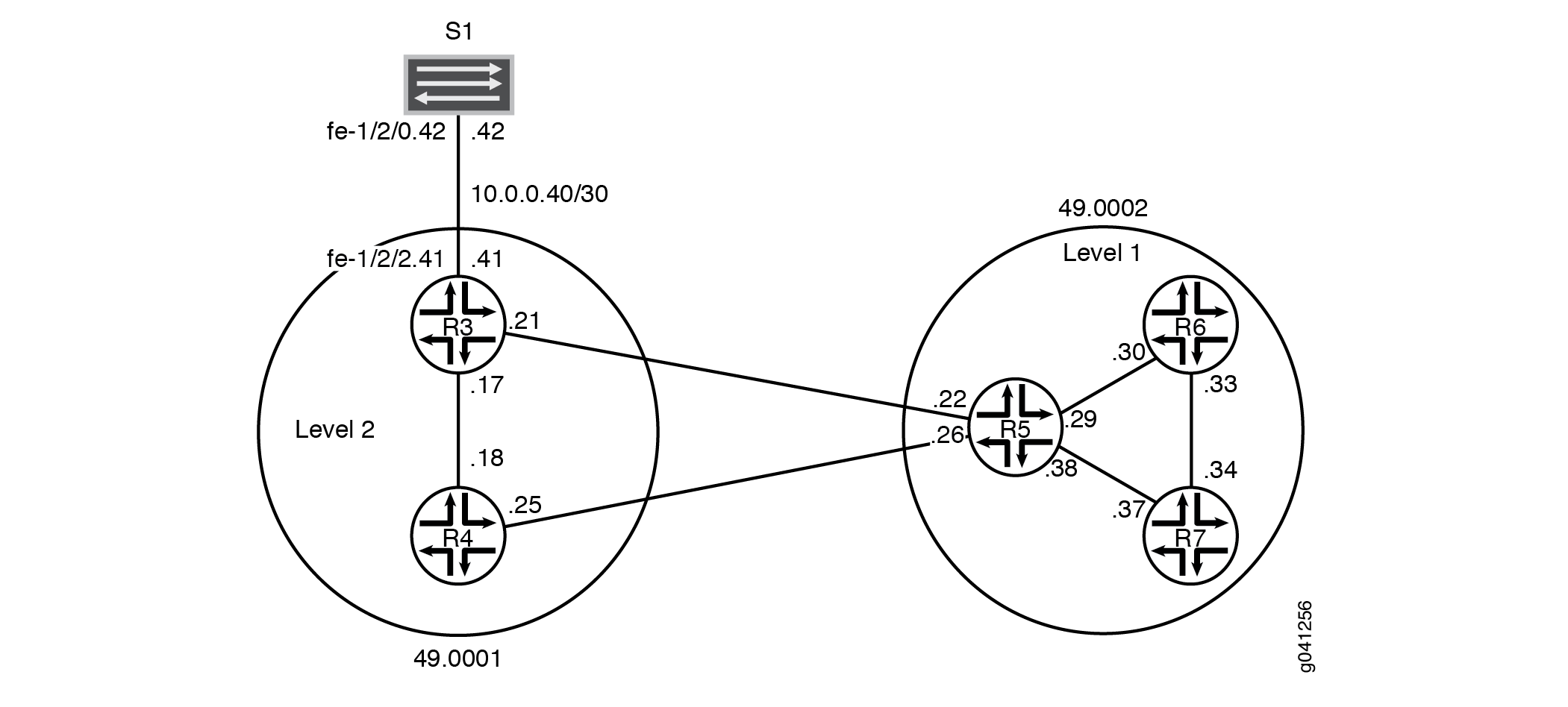
CLIクイックコンフィグレーション は、 図1に示すすべてのデバイスの構成を示しています。 セクション #configuration69__isis-multi-level-step-by-step では、 デバイス R5 の手順について説明します。
この例には以下の特徴があります。
-
デバイスR5は、レベル1/レベル2ルーターとして機能し、デバイスR6とデバイスR7を含むレベル2バックボーンエリア49.0001とレベル1エリア49.0002を相互接続します。
-
システムIDは、デバイスのIPv4 lo0アドレスに基づいています。
-
個々のインターフェイスが失われても、IS-ISの運用が完全に中断されるわけではありません。
-
すべてのルーターのIPv4 lo0アドレスは、IS-IS経由で到達可能です。
-
デバイスR3とデバイスS1の間のリンクは、エリア内ルートとしてエリア49.0001に表示されます。このインターフェイスでは、IS-IS隣接関係を確立できません。これを実現するには、デバイスR3のデバイスS1へのインターフェイスで
passiveステートメントを設定します。 -
レベル2デバイスのループバックアドレスは、レベル1エリアには表示されません。
-
各デバイスペアリングには1つの隣接関係しかありません。
トポロジー
設定
手順
CLIクイックコンフィグレーション
この例をすばやく設定するには、以下のコマンドをコピーしてテキストファイルに貼り付け、改行を削除して、ネットワーク構成に合わせて必要な詳細を変更してから、コマンドを [edit] 階層レベルのCLIにコピー&ペーストします。
デバイスR3
set interfaces fe-1/2/0 unit 0 description to-R4
set interfaces fe-1/2/0 unit 0 family inet address 10.0.0.17/30
set interfaces fe-1/2/0 unit 0 family iso
set interfaces fe-1/2/1 unit 0 description to-R5
set interfaces fe-1/2/1 unit 0 family inet address 10.0.0.21/30
set interfaces fe-1/2/1 unit 0 family iso
set interfaces fe-1/2/2 unit 0 family inet address 10.0.0.41/30
set interfaces fe-1/2/2 unit 0 description to-S1
set interfaces lo0 unit 0 family inet address 192.168.0.3/32
set interfaces lo0 unit 0 family iso address 49.0001.1921.6800.0003.00
set protocols isis interface fe-1/2/0.0 level 1 disable
set protocols isis interface fe-1/2/1.0 level 1 disable
set protocols isis interface lo0.0 level 1 disable
set protocols isis interface fe-1/2/2.0 passive
デバイスR4
set interfaces fe-1/2/0 unit 0 description to-R3
set interfaces fe-1/2/0 unit 0 family inet address 10.0.0.18/30
set interfaces fe-1/2/0 unit 0 family iso
set interfaces fe-1/2/1 unit 0 description to-R5
set interfaces fe-1/2/1 unit 0 family inet address 10.0.0.25/30
set interfaces fe-1/2/1 unit 0 family iso
set interfaces lo0 unit 0 family inet address 192.168.0.4/32
set interfaces lo0 unit 0 family iso address 49.0001.0192.0168.0004.00
set protocols isis interface fe-1/2/0.0 level 1 disable
set protocols isis interface fe-1/2/1.0 level 1 disable
set protocols isis interface lo0.0 level 1 disable
デバイスR5
set interfaces fe-1/2/0 unit 0 description to-R3
set interfaces fe-1/2/0 unit 0 family inet address 10.0.0.22/30
set interfaces fe-1/2/0 unit 0 family iso
set interfaces fe-1/2/1 unit 0 description to-R4
set interfaces fe-1/2/1 unit 0 family inet address 10.0.0.26/30
set interfaces fe-1/2/1 unit 0 family iso
set interfaces fe-1/2/2 unit 0 description to-R6
set interfaces fe-1/2/2 unit 0 family inet address 10.0.0.29/30
set interfaces fe-1/2/2 unit 0 family iso
set interfaces fe-1/2/3 unit 0 description to-R7
set interfaces fe-1/2/3 unit 0 family inet address 10.0.0.38/30
set interfaces fe-1/2/3 unit 0 family iso
set interfaces lo0 unit 0 family inet address 192.168.0.5/32
set interfaces lo0 unit 0 family iso address 49.0002.0192.0168.0005.00
set protocols isis interface fe-1/2/0.0 level 1 disable
set protocols isis interface fe-1/2/1.0 level 1 disable
set protocols isis interface fe-1/2/2.0 level 2 disable
set protocols isis interface fe-1/2/3.0 level 2 disable
set protocols isis interface lo0.0 level 1 disable
デバイスR6
set interfaces fe-1/2/0 unit 0 description to-R5
set interfaces fe-1/2/0 unit 0 family inet address 10.0.0.30/30
set interfaces fe-1/2/0 unit 0 family iso
set interfaces fe-1/2/1 unit 0 description to-R7
set interfaces fe-1/2/1 unit 0 family inet address 10.0.0.33/30
set interfaces fe-1/2/1 unit 0 family iso
set interfaces lo0 unit 0 family inet address 192.168.0.6/32
set interfaces lo0 unit 0 family iso address 49.0002.0192.0168.0006.00
set protocols isis interface fe-1/2/0.0 level 2 disable
set protocols isis interface fe-1/2/1.0 level 2 disable
set protocols isis interface lo0.0 level 2 disable
デバイスR7
set interfaces fe-1/2/0 unit 0 description to-R6
set interfaces fe-1/2/0 unit 0 family inet address 10.0.0.34/30
set interfaces fe-1/2/0 unit 0 family iso
set interfaces fe-1/2/1 unit 0 description to-R5
set interfaces fe-1/2/1 unit 0 family inet address 10.0.0.37/30
set interfaces fe-1/2/1 unit 0 family iso
set interfaces lo0 unit 0 family inet address 192.168.0.7/32
set interfaces lo0 unit 0 family iso address 49.0002.0192.0168.0007.00
set protocols isis interface fe-1/2/0.0 level 2 disable
set protocols isis interface fe-1/2/1.0 level 2 disable
set protocols isis interface lo0.0 level 2 disable
デバイスS1
set interfaces fe-1/2/0 unit 0 family inet address 10.0.0.42/30
set interfaces fe-1/2/0 unit 0 description to-R3
ステップバイステップの手順
次の例では、設定階層のさまざまなレベルに移動する必要があります。CLIのナビゲーションについては、『CLIユーザーガイド』の「設定モードでのCLIエディターの使用」を参照してください。
マルチレベル IS-IS を設定するには:
-
ネットワークインターフェイスを設定します。
各インターフェイスにISOアドレスファミリーを含めることで、インターフェイスでIS-ISを有効にします。
[edit interfaces]
user@R5# set fe-1/2/0 unit 0 description to-R3
user@R5# set fe-1/2/0 unit 0 family inet address 10.0.0.22/30
user@R5# set fe-1/2/0 unit 0 family iso
user@R5# set fe-1/2/1 unit 0 description to-R4
user@R5# set fe-1/2/1 unit 0 family inet address 10.0.0.26/30
user@R5# set fe-1/2/1 unit 0 family iso
user@R5# set fe-1/2/2 unit 0 description to-R6
user@R5# set fe-1/2/2 unit 0 family inet address 10.0.0.29/30
user@R5# set fe-1/2/2 unit 0 family iso
user@R5# set fe-1/2/3 unit 0 description to-R7
user@R5# set fe-1/2/3 unit 0 family inet address 10.0.0.38/30
user@R5# set fe-1/2/3 unit 0 family iso
-
2つのループバックインターフェイスアドレスを設定します。
1 つのアドレスは IPv4 用です。
もう 1 つは、IS-IS エリア 49.0002 用で、デバイス R5 がエリア 49.0002 内の他のレベル 1 デバイスと隣接関係を形成できるようにします。デバイスR5のNETがレベル1エリア49.0002に属していると認識しても、そのループバックインターフェイスはレベル1インターフェイスとして設定されていません。これを行うと、デバイスR5のループバックへのルートがレベル1エリアに注入されます。
[edit interfaces lo0 unit 0]
user@R5# set family inet address 192.168.0.5/32
user@R5# set family iso address 49.0002.0192.0168.0005.00
-
インターフェイスごとに IS-IS レベルを指定します。
デバイスR5は、各リンクの同じレベルで他のルーティングデバイスと隣接します。
デフォルトでは、IS-ISは、ISOプロトコルファミリーが有効になっているすべてのインターフェイスのIS-ISエリアに対して(
[edit interfaces interface-name unit logical-unit-number]階層レベルで)有効になっています。インターフェイス上の特定のレベルでIS-ISを無効にするには、disableステートメントを含めます。デバイスR5のループバックインターフェイスは、レベル2のみを実行するように設定されています。レベル 1 の動作が lo0.0 で有効になっている場合、デバイス R5 はレベル 1 のリンク状態 PDU にそのループバック アドレスを含めます。これは、レベル 2 デバイスのループバック アドレスをレベル 1 エリアに表示してはならないこの例では正しくありません。
OSPFとは異なり、このインターフェイスはルーターのNETのソースであるため、IS-ISインターフェイスとして設定する必要があるため、
[edit protocols isis]階層レベルでルーターのlo0インターフェイスを明示的にリストする必要があります。IS-ISでは、lo0インターフェイスはデフォルトでパッシブモードで動作します。仮想インターフェイスでは隣接関係の形成が発生しないため、これは理想的です。[edit protocols isis] user@R5# set interface fe-1/2/0.0 level 1 disable user@R5# set interface fe-1/2/1.0 level 1 disable user@R5# set interface fe-1/2/2.0 level 2 disable user@R5# set interface fe-1/2/3.0 level 2 disable user@R5# set interface lo0.0 level 1 disable
結果
設定モードから、 show interfaces および show protocols コマンドを入力して設定を確認します。出力に意図した設定が表示されない場合は、この例の手順を繰り返して設定を修正します。
user@R5# show interfaces
fe-1/2/0 {
    unit 0{
        description to-R3;
        family inet {
            address 10.0.0.22/30;
        }
        family iso;
    }
}
fe-1/2/1 {
    unit 0 {
        description to-R4;
        family inet {
            address 10.0.0.26/30;
        }
        family iso;
    }
}
fe-1/2/2 {
    unit 0 {
        description to-R6;
        family inet {
            address 10.0.0.29/30;
        }
        family iso;
    }
}
fe-1/2/3 {
    unit 0 {
        description to-R7;
        family inet {
            address 10.0.0.38/30;
        }
        family iso;
    }
}
lo0 {
    unit 0 {
        family inet {
            address 192.168.0.5/32;
        }
        family iso {
            address 49.0002.0192.0168.0005.00;
        }
    }
}
user@R5# show protocols
isis {
    interface fe-1/2/0.0 {
        level 1 disable;
    }
    interface fe-1/2/1.0 {
        level 1 disable;
    }
    interface fe-1/2/2.0 {
        level 2 disable;
    }
    interface fe-1/2/3.0 {
        level 2 disable;
    }
    interface lo0.0 {
        level 1 disable;
    }
}
デバイスの設定が完了したら、設定モードから commit を入力します。
検証
設定が正常に機能していることを確認します。
インターフェイスとエリアの関連付けの確認
目的
インターフェイスとエリアの関連付けが想定どおりに設定されていることを確認します。
アクション
動作モードから、 show isis interface コマンドを入力します。
user@R5> show isis interface
IS-IS interface database:
Interface             L CirID Level 1 DR       Level 2 DR       L1/L2 Metric
lo0.0                 3   0x1 Disabled          Passive             0/0
fe-1/2/0.0           2   0x3 Disabled          R5.03              10/10
fe-1/2/1.0           2   0x2 Disabled          R5.02              10/10
fe-1/2/2.0           1   0x1 R6.02         Disabled               10/10
fe-1/2/3.0           1   0x4 R5.04         Disabled               10/10
意味
出力は、デバイスR5のインターフェイスがISOファミリーで正しく設定されており、インターフェイスが正しいレベルに配置されていることを示しています。
また、デバイスR5がブロードキャスト対応IS-ISインターフェイス上で、自身を指定中間システム(DIS)として選択していることもわかります。
IS-IS隣接関係の検証
目的
デバイスR5とそのIS-ISネイバーの間に予想される隣接関係が形成されていることを確認します。
アクション
動作モードから、 show isis adjacency detail コマンドを入力します。
user@R5> show isis adjacency detail
R3
  Interface: fe-1/2/0.0, Level: 2, State: Up, Expires in 25 secs
  Priority: 64, Up/Down transitions: 1, Last transition: 03:19:31 ago
  Circuit type: 2, Speaks: IP, IPv6, MAC address: 0:5:85:8f:c8:bc
  Topologies: Unicast
  Restart capable: Yes, Adjacency advertisement: Advertise
  LAN id: R5.03, IP addresses: 10.0.0.21

R4
  Interface: fe-1/2/1.0, Level: 2, State: Up, Expires in 24 secs
  Priority: 64, Up/Down transitions: 1, Last transition: 03:19:36 ago
  Circuit type: 2, Speaks: IP, IPv6, MAC address: 0:5:85:8f:c8:bc
  Topologies: Unicast
  Restart capable: Yes, Adjacency advertisement: Advertise
  LAN id: R5.02, IP addresses: 10.0.0.25

R6
  Interface: fe-1/2/2.0, Level: 1, State: Up, Expires in 6 secs
  Priority: 64, Up/Down transitions: 1, Last transition: 03:20:24 ago
  Circuit type: 1, Speaks: IP, IPv6, MAC address: 0:5:85:8f:c8:bd
  Topologies: Unicast
  Restart capable: Yes, Adjacency advertisement: Advertise
  LAN id: R6.02, IP addresses: 10.0.0.30

R7
  Interface: fe-1/2/3.0, Level: 1, State: Up, Expires in 21 secs
  Priority: 64, Up/Down transitions: 1, Last transition: 03:19:29 ago
  Circuit type: 1, Speaks: IP, IPv6, MAC address: 0:5:85:8f:c8:bc
  Topologies: Unicast
  Restart capable: Yes, Adjacency advertisement: Advertise
  LAN id: R5.04, IP addresses: 10.0.0.37
意味
これらの結果から、デバイスR5に2つのレベル2隣接関係と2つのレベル1隣接関係があることが確認できます。
IS-ISデータベースの検証
目的
デバイスR5はレベル1/レベル2(L1/L2)に接続されたルーターであるため、エリア49.0002に関連付けられたレベル1のリンク状態データベースを調べて、バックボーンルーターからのループバックアドレスがレベル1エリアにアドバタイズされていないことを確認します。
アクション
動作モードから、 show isis database detail コマンドを入力します。
user@R5> show isis database detail
IS-IS level 1 link-state database:

R5.00-00 Sequence: 0x19, Checksum: 0x7488, Lifetime: 727 secs
   IS neighbor: R5.04                     Metric:       10
   IS neighbor: R6.02                     Metric:       10
   IP prefix: 10.0.0.28/30                    Metric:       10 Internal Up
   IP prefix: 10.0.0.36/30                    Metric:       10 Internal Up

R5.04-00 Sequence: 0x14, Checksum: 0x2668, Lifetime: 821 secs
   IS neighbor: R5.00                     Metric:        0
   IS neighbor: R7.00                     Metric:        0

R6.00-00 Sequence: 0x17, Checksum: 0xa65, Lifetime: 774 secs
   IS neighbor: R6.02                     Metric:       10
   IS neighbor: R7.02                     Metric:       10
   IP prefix: 10.0.0.28/30                    Metric:       10 Internal Up
   IP prefix: 10.0.0.32/30                    Metric:       10 Internal Up
   IP prefix: 192.168.0.6/32                  Metric:        0 Internal Up

R6.02-00 Sequence: 0x13, Checksum: 0xd1c0, Lifetime: 908 secs
   IS neighbor: R5.00                     Metric:        0
   IS neighbor: R6.00                     Metric:        0

R7.00-00 Sequence: 0x17, Checksum: 0xe39, Lifetime: 775 secs
   IS neighbor: R5.04                     Metric:       10
   IS neighbor: R7.02                     Metric:       10
   IP prefix: 10.0.0.32/30                    Metric:       10 Internal Up
   IP prefix: 10.0.0.36/30                    Metric:       10 Internal Up
   IP prefix: 192.168.0.7/32                  Metric:        0 Internal Up

R7.02-00 Sequence: 0x13, Checksum: 0x404d, Lifetime: 966 secs
   IS neighbor: R6.00                     Metric:        0
   IS neighbor: R7.00                     Metric:        0

IS-IS level 2 link-state database:

R3.00-00 Sequence: 0x17, Checksum: 0x5f84, Lifetime: 1085 secs
   IS neighbor: R4.02                     Metric:       10
   IS neighbor: R5.03                     Metric:       10
   IP prefix: 10.0.0.16/30                    Metric:       10 Internal Up
   IP prefix: 10.0.0.20/30                    Metric:       10 Internal Up
   IP prefix: 10.0.0.40/30                    Metric:       10 Internal Up
   IP prefix: 192.168.0.3/32                  Metric:        0 Internal Up

R4.00-00 Sequence: 0x17, Checksum: 0xab3a, Lifetime: 949 secs
   IS neighbor: R4.02                     Metric:       10
   IS neighbor: R5.02                     Metric:       10
   IP prefix: 10.0.0.16/30                    Metric:       10 Internal Up
   IP prefix: 10.0.0.24/30                    Metric:       10 Internal Up
   IP prefix: 192.168.0.4/32                  Metric:        0 Internal Up

R4.02-00 Sequence: 0x14, Checksum: 0xf2a8, Lifetime: 1022 secs
   IS neighbor: R3.00                     Metric:        0
   IS neighbor: R4.00                     Metric:        0

R5.00-00 Sequence: 0x1f, Checksum: 0x20d7, Lifetime: 821 secs
   IS neighbor: R5.02                     Metric:       10
   IS neighbor: R5.03                     Metric:       10
   IP prefix: 10.0.0.20/30                    Metric:       10 Internal Up
   IP prefix: 10.0.0.24/30                    Metric:       10 Internal Up
   IP prefix: 10.0.0.28/30                    Metric:       10 Internal Up
   IP prefix: 10.0.0.32/30                    Metric:       20 Internal Up
   IP prefix: 10.0.0.36/30                    Metric:       10 Internal Up
   IP prefix: 192.168.0.5/32                  Metric:        0 Internal Up
   IP prefix: 192.168.0.6/32                  Metric:       10 Internal Up
   IP prefix: 192.168.0.7/32                  Metric:       10 Internal Up

R5.02-00 Sequence: 0x14, Checksum: 0x6135, Lifetime: 977 secs
   IS neighbor: R4.00                     Metric:        0
   IS neighbor: R5.00                     Metric:        0

R5.03-00 Sequence: 0x14, Checksum: 0x1483, Lifetime: 1091 secs
   IS neighbor: R3.00                     Metric:        0
   IS neighbor: R5.00                     Metric:        0
意味
この画面は、デバイスR5のループバックインターフェイスがレベル2のみを実行するように正しく設定されていることを示します。レベル 1 の動作が lo0.0 で有効になっていれば、デバイス R5 はレベル 1 のリンクステート PDU にそのループバック アドレスを含めていたはずです。
また、デバイスR5には、隣接するネイバーから受信したレベル2のリンクステートPDUがあることもわかります。
OSPFの完全にスタビーなエリアと同様に、デフォルトでは、バックボーン(レベル2)や外部プレフィックスがレベル1のエリアにリークされることはありません。ただし、デバイスR5のレベル2リンクステートPDUに見られるように、レベル1のプレフィックスはIS-ISバックボーンにリークされます。