シリアル インターフェイス
シリアルインターフェイス、シリアル回線プロトコル、シリアルクロッキングモード、シリアル信号処理、シリアルDTR回線、シリアル信号の極性、シリアルループバック機能、シリアル回線エンコーディングの設定方法について説明します。
シリアルインターフェイスは、シリアル回線プロトコルを使用したポイントツーポイント広域ネットワーク(WAN)接続用のジュニパーデバイス上のネットワークポートです。シリアルインターフェイスは、柔軟なプロトコル、エンコーディング、クロッキング、シグナリングオプションを備えたWAN接続を提供します。シリアル インターフェイスはシリアル リンクを介した通信を可能にし、ネットワーク管理者は従来の回線接続にシリアル インターフェイスを実装します。
利点:
-
シリアル インターフェイスは、送信および受信デバイスまたは IC を接続するためのシンプルでコスト効率の高い方法を提供します。
-
シリアルインターフェイスは、他のインターフェイスよりも導線の数が少なくて済み(多くの場合、1本のみ)、実装が容易になります。
-
シリアルインターフェイスは、長距離通信をサポートします。
シリアル インターフェイスの概要
シリアルインターフェイスを介して通信するデバイスは、DTE(データ端末機器)とDCE(データ回線終端機器)の2つのクラスに分類されます。ジュニパーネットワークスのシリアルPIC(物理インターフェイスカード)は、PICごとに2つのポートを持ち、全二重データ伝送をサポートします。これらのPICは、DTEモードのみをサポートします。
|
インターフェイスの詳細 |
説明 |
|---|---|
|
インターフェイス名 |
シリアルインターフェイス |
|
サポート対象 |
プラットフォームのサポートについては、 ハードウェア互換性ツール(HCT)をご覧ください。 |
|
シリアルインターフェイスタイプを設定するための規格 |
|
|
サポートされる機能 |
|
|
論理プロパティ |
シリアルインターフェイス固有の論理プロパティはありません。設定可能な一般的な論理プロパティについては、 論理インターフェイスの設定を参照してください。シリアルインターフェイスでのこのサポートは、T1およびE1インターフェイスでの既存のLFIおよびMLPPPサポートと同じです。 |
シリアル伝送
基本的なシリアル通信では、9つの信号が伝送に不可欠です。各信号は、9ピンまたは25ピンコネクタのいずれかのピンに関連付けられています。
|
信号名 |
定義 |
信号源 |
|---|---|---|
|
TD |
送信データ |
DTE |
|
RD |
受信データ |
DCE |
|
RTS |
送信依頼 |
DTE |
|
CTS |
送信をクリア |
DCE |
|
DSR |
データセットの準備ができました |
DCE |
|
信号接地 |
接地信号 |
– |
|
CD |
キャリア検出 |
– |
|
DTR |
データ端末に対応 |
DTE |
|
RI |
リングインジケーター |
– |
シリアル回線プロトコルのガイドライン:
-
DCE は DSR 信号を DTE に送信し、DTE は DTR 信号で応答します。これによりリンクが確立され、トラフィックを通過させることができます。
-
DTE デバイスがデータを受信する準備ができたら、次の手順に従います。
-
RTS信号をマークされた状態(すべて1)に設定し、データを送信できることをDCEに示します。DTE がデータを受信できない場合(バッファー条件など)、RTS 信号はすべて 0 に設定されます。
-
CTS信号をマークされた状態に設定して、データを送信できることをDTEに示します。DCEがデータを受信できない場合、CTS信号はすべて0に設定されます。
-
-
情報を送信すると、送信データ(TD)ラインを経由してデータを送信し、受信データ(RD)ラインを経由してデータを受信します。
-
TDライン - DTEデバイスからDCEデバイスにデータが送信されるライン
-
RD回線—DCEデバイスからDTEデバイスにデータが送信される回線
-
-
ワイヤ名はデータフローの方向を示すものではありません。
シリアル ポートがオープンになっている場合、DTE デバイスは DTR 信号をマークされた状態に設定します。同様に、DCE は DSR 信号をマークされた状態に設定します。しかし、RTS信号とCTS信号でネゴシエーションが行われるため、DTR信号とDSR信号はほとんど利用されません。
キャリア検出とリングインジケーター信号は、リモートモデムとの接続を検出しますが、これらの信号はほとんど使用されません。
SRXデバイス上の8ポート同期シリアルGPIM
ギガビットバックプレーン 物理インターフェイスモジュール (GPIM)は、SRX550 サービスゲートウェイの前面スロットに取り付けて、LAN または WAN への物理接続を提供することができるネットワーク インターフェイス カード(NIC)です。8ポート同期シリアルGPIMは、シリアルネットワークメディアタイプへの物理接続を提供し、ネットワークの受信パケットと送信パケットの送信を行います。GPIMは、処理用のパケットを転送するだけでなく、フレーミングとラインスピードシグナリングも実行します。このGPIMは、同期モードで動作する8つのポートを提供し、ポートあたり64Mbpsまたは8Mbpsのラインレートをサポートします。
8ポートシリアルGPIMの設定については、「 8ポートシリアルGPIMの基本設定」を参照してください。
8ポート同期シリアルGPIMでサポートされている機能
|
特長 |
説明 |
|---|---|
|
動作モード(ケーブルに基づいた自動選択、設定不要) |
|
|
クロッキング |
|
|
クロックレート(ボーレート) |
1.2KHz〜8.0MHz RS-232 シリアル インターフェイスは、200 KHz を超えるクロック レートでエラーが発生する可能性があります。 |
|
MTU |
9192バイト、デフォルト値は1504バイトです |
|
HDLC機能 |
|
|
行エンコーディング |
NRZおよびNRZI |
|
データの反転 |
有効 |
|
回線プロトコル |
EIA530/EIA530A、X.21、RS-449、RS-232、V.35 |
|
データケーブル |
回線プロトコルごとに個別のケーブル(DTE/DCEモード両方) |
|
エラーカウンター(ANSI仕様に準拠) |
有効 |
|
アラームと障害 |
|
|
データ信号 |
Rx クロック |
|
制御信号 |
|
|
シリアル自動再同期 |
|
|
診断機能 |
|
|
レイヤー2機能 |
カプセル化
|
|
SNMP 機能 |
各ポートで受信可能なSNMP情報
|
|
偽造防止チェック |
有効 |
シリアル回線プロトコルを設定する
シリアル回線プロトコルを設定する
デフォルトでは、シリアルインターフェイスはEIA-530ラインプロトコルを使用します。PICの各ポートは、以下のラインプロトコルのいずれかを使用するように独立して設定することができます。
-
EIA-530
-
V.35
-
X.21
シリアル回線プロトコルを設定するには:
eia530、v.35、またはx.21オプションを指定するline-protocolステートメントを含めます。
line-protocol protocol;
以下の階層レベルでこれらのステートメントを含めることができます。
-
[edit interfaces se-pim/0/port serial-options] -
[edit interfaces se-fpc/pic/port serial-options]
シリアルインターフェイスの詳細については、次のセクションを参照してください。
シリアルインターフェイスのデフォルト設定
シリアルインターフェイスのデフォルト設定
EIA-530インターフェイスのデフォルト設定
line-protocolステートメントを含めない場合、またはデフォルトのEIA-530ラインプロトコルを明示的に設定した場合、デフォルトの設定は次のとおりです。
dce-options | dte-options {
    cts normal;
    dcd normal;
    dsr normal;
    dtr normal;
    rts normal;
    tm normal;
}
clock-rate 16.384mhz;
clocking-mode loop;
cts-polarity positive;
dcd-polarity positive;
dsr-polarity positive;
dtr-circuit balanced;
dtr-polarity positive;
encoding nrz;
rts-polarity positive;
tm-polarity positive;
以下の階層レベルで line-protocol ステートメントを含めることができます。
-
[edit interfaces se-pim/0/port serial-options] -
[edit interfaces se-fpc/pic/port serial-options]
V.35 インターフェイスのデフォルト設定
line-protocol v.35ステートメントを含める場合、デフォルト設定は次のとおりです。
dce-options | dte-options {
    cts normal;
    dcd normal;
    dsr normal;
    dtr normal;
    rts normal;
}
clock-rate 16.384mhz;
clocking-mode loop;
cts-polarity positive;
dcd-polarity positive;
dsr-polarity positive;
dtr-circuit balanced;
dtr-polarity positive;
encoding nrz;
rts-polarity positive;
以下の階層レベルで line-protocol ステートメントを含めることができます。
-
[edit interfaces se-pim/0/port serial-options] -
[edit interfaces se-fpc/pic/port serial-options]
X.21インターフェイスのデフォルト設定
line-protocol x.21 ステートメントを含める場合、デフォルト設定は次のとおりです。
dce-options | dte-options {
    control-signal normal;
    indication normal;
}
clock-rate 16.384mhz;
clocking-mode loop;
control-polarity positive;
encoding nrz;
indication-polarity positive;
以下の階層レベルで line-protocol ステートメントを含めることができます。
-
[edit interfaces se-pim/0/port serial-options] -
[edit interfaces se-fpc/pic/port serial-options]
無効なシリアルインターフェイスステートメント
以下のセクションでは、各タイプのシリアルインターフェイスに対して無効な設定ステートメントを示しています。設定に以下のステートメントを含めると、エラーメッセージでエラーの場所が示され、設定は有効になりません。
無効なEIA-530インターフェイスステートメント
line-protocolステートメントを含めない場合、またはデフォルトのEIA-530ラインプロトコルを明示的に設定した場合、以下のステートメントは無効になります。
dce-options | dte-options {
    control-signal (assert | de-assert | normal);
    indication (ignore | normal | require);
}
control-polarity (negative | positive);
indication-polarity (negative | positive);
以下の階層レベルで line-protocol ステートメントを含めることができます。
-
[edit interfaces se-pim/0/port serial-options] -
[edit interfaces se-fpc/pic/port serial-options]
無効なV.35インターフェイスステートメント
line-protocol v.35ステートメントを含めると、以下のステートメントは無効になります。
dce-options | dte-options {
    control-signal (assert | de-assert | normal);
    indication (ignore | normal | require);
    tm (ignore | normal | require);
}
control-polarity (negative | positive);
indication-polarity (negative | positive);
loopback (dce-local | dce-remote);
tm-polarity (negative | positive);
以下の階層レベルで line-protocol ステートメントを含めることができます。
-
[edit interfaces se-pim/0/port serial-options] -
[edit interfaces se-fpc/pic/port serial-options]
無効なX.21インターフェイスステートメント
line-protocol x.21ステートメントを含めると、以下のステートメントは無効になります。
dce-options | dte-options {
    cts (ignore | normal | require);
    dcd (ignore | normal | require);
    dsr (ignore | normal | require);
    dtr (assert | de-assert | normal);
    rts (assert | de-assert | normal);
    tm (ignore | normal | require);
}
clocking-mode (dce | internal);
cts-polarity (negative | positive);
dce-polarity (negative | positive);
dsr-polarity (negative | positive);
dtr-circuit (balanced | unbalanced);
dtr-polarity (negative | positive);
loopback (dce-local | dce-remote);
rts-polarity (negative | positive);
tm-polarity (negative | positive);
以下の階層レベルで line-protocol ステートメントを含めることができます。
-
[edit interfaces se-pim/0/port serial-options] -
[edit interfaces se-fpc/pic/port serial-options]
シリアルクロッキングモードを設定する
シリアルクロッキングモードを設定する
デフォルトでは、シリアルインターフェイスはループクロッキングモードを使用します。EIA-530およびV.35インターフェイスでは、PICの各ポートを独立して設定して、ループ、DCE、または内部クロッキングモードを使用できます。X.21インターフェイスでは、ループクロッキングモードのみサポートされます。
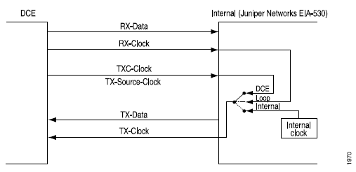
3 つのクロッキング モードは、次のように機能します。
-
ループクロッキングモード—DCEのRXクロックを使用して、DCEからDTEにデータをクロックします。
-
DCEクロッキングモード—DTEがDTEの送信クロックとして使用するためにDCEによって生成されたTXCクロックを使用します。
-
内部クロッキングモード—ラインタイミングとも呼ばれ、内部で生成されたクロックを使用します。
[edit interfaces se-pim/0/port serial-options]または[edit interfaces se-fpc/pic/port dte-options]階層レベルでclock-rateステートメントを含めることで、このクロックの速度を設定できます。DTEクロックレートの詳細については、DTEクロックレートの設定を参照してください。
DCEクロッキングモードとループクロッキングモードは、DCEによって生成された外部クロックを使用することに注意してください。
図1 は、ループ、DCE、および内部クロッキングモードのクロックソースを示しています。
シリアルインターフェイスのクロッキングモードを設定するには、 clocking-mode ステートメントを含めます。
clocking-mode (dce | internal | loop);
以下の階層レベルでこのステートメントを含めることができます。
-
[edit interfaces se-pim/0/port serial-options] -
[edit interfaces se-fpc/pic/port serial-options]
シリアルインターフェイス送信クロックを反転する
外部タイミング クロッキング モード(DCE またはループ)を使用する場合、長いケーブルにより DTE から送信されるクロックとデータの位相シフトが発生する可能性があります。高速では、この位相シフトによりエラーが発生することがあります。送信クロックを反転すると位相シフトが修正されるため、エラー率が低くなります。
デフォルトでは、送信クロックは反転しません。送信クロックを反転するには、 transmit-clock invert ステートメントを含めます。
transmit-clock invert;
以下の階層レベルでこのステートメントを含めることができます。
-
[edit interfaces se-pim/0/port serial-options] -
[edit interfaces se-fpc/pic/port serial-options]
DTEクロックレートを設定する
デフォルトのシリアルインターフェイスのクロックレートは16.384MHz です。内部クロッキングモードが設定されたEIA-530およびV.35インターフェイスでは、クロックレートを設定できます。
クロックレートを設定するには、 clock-rate ステートメントを含めます。
clock-rate rate;
以下の階層レベルでこのステートメントを含めることができます。
-
[edit interfaces se-pim/0/port serial-options] -
[edit interfaces se-fpc/pic/port serial-options]
以下のインターフェイス速度を設定できます。
-
2.048MHz
-
2.341MHz
-
2.731MHz
-
3.277MHz
-
4.096MHz
-
5.461MHz
-
8.192MHz
-
16.384MHz
シリアル インターフェイスはデフォルトのレートである 16.384 MHz での使用を想定していますが、次の条件のいずれかに該当する場合は、より遅いレートの使用が必要になる場合があります。
-
相互接続ケーブルが長すぎて効果的な動作ができません。
-
相互接続ケーブルは、信号導体とケーブルの負荷端で共通の回路との間で差動的に測定された+1ボルトを超える不要な電圧を引き起こす可能性のある外部ノイズ源にさらされ、ジェネレータの代わりに50オームの抵抗を使用します。
-
他の信号との干渉を最小限に抑える必要があります。
-
信号を反転する必要があります
シグナリングレートとインターフェイスケーブル距離の関係の詳細については、次の規格を参照してください。
-
EIA-422-A、 平衡電圧デジタルインターフェイス回路の電気的特性
-
EIA-423-A、 不平衡電圧デジタルインターフェイス回路の電気的特性
シリアル信号処理を設定する
デフォルトでは、通常の信号処理がすべての信号に対して有効になっています。各信号について、 normal オプションは、次の規格で定義されているように、その信号の通常の信号処理に適用されます。
-
TIA/EIA規格530
-
ITU-T 勧告 V.35
-
ITU-T 勧告 X.21
表4は 、各信号タイプをサポートするシリアルインターフェイスモードを示しています。
|
信号 |
シリアル インターフェイス |
|---|---|
| DCE信号 | |
|
送信許可(CTS) |
EIA-530およびV.35 |
|
データキャリア検出(DCD) |
EIA-530およびV.35 |
|
データセット準備完了(DSR) |
EIA-530およびV.35 |
|
表示 |
X.21のみ |
|
テストモード(TM) |
EIA-530のみ |
| DCEへの信号 | |
|
制御信号 |
X.21のみ |
|
データ転送対応(DTR) |
EIA-530およびV.35 |
|
送信リクエスト(RTS) |
EIA-530およびV.35 |
シリアルインターフェイスの信号特性を設定するには、 dce-options または dte-options ステートメントを含めます。
dce-options |dte-options {
    control-signal (assert | de-assert | normal);
    cts (ignore | normal | require);
    dcd (ignore | normal | require);
    dsr (ignore | normal | require);
    dtr signal-handling-option;
    ignore-all;
    indication (ignore | normal | require);
    rts (assert | de-assert | normal);
    tm (ignore | normal | require);
}
以下の階層レベルでこれらのステートメントを含めることができます。
-
[edit interfaces se-pim/0/port serial-options] -
[edit interfaces se-fpc/pic/port serial-options]
EIA-530およびV.35インターフェイスでは、 dtr および rts ステートメントを含め、 assert、 de-assert、または normal オプションを指定して、DCEへの信号を設定します。
dtr (assert | de-assert | normal);
rts (assert | de-assert | normal);
X.21インターフェイスの場合、assert、de-assert、またはnormalオプションを指定して、control-signalステートメントを含めてDCEへの信号を設定します。
control-signal (assert | de-assert | normal);
アサーションとは 、特定の信号の正側が潜在的な高レベル出力電圧(Voh)にあり、同じ信号の負の側が潜在的な低レベル出力電圧(Vol)にある場合です。 デアサーションとは 、特定の信号の正の側が潜在的なVolにあり、同じ信号の負の側が潜在的なVohにある場合です。
DTR信号については、 dtr ステートメントを含め、 auto-synchronize オプションを指定することで、自動再同期用の信号を使用して通常の信号処理を設定できます。
dtr {
    auto-synchronize {
        duration milliseconds;
        interval seconds;
    }
}
再同期のパルス持続時間は、1〜1000ミリ秒です。再同期のオフセット間隔は、1秒から31秒までです。
EIA-530およびV.35インターフェイスでは、 cts、 dcd、および dsr ステートメントを含め、 ignore、 normal、または require オプションを指定して、from-DCE信号を設定します。
cts (ignore | normal | require);
dcd (ignore | normal | require);
dsr (ignore | normal | require);
X.21インターフェイスの場合、ignore、normal、またはrequireオプションを指定して、indicationステートメントを含めて、from-DCE信号を設定します。
indication (ignore | normal | require);
EIA-530インターフェイスの場合のみ、 tm ステートメントを含め、 ignore、 normal、または require オプションを指定することで、from-DCEテストモード(TM)シグナリングを設定できます。
tm (ignore | normal | require);
from-DCE信号をアサートする必要があることを指定するには、設定に require オプションを含めます。from-DCE信号を無視することを指定するには、設定に ignore オプションを含めます。
V.35およびX.21インターフェイスでは、設定に tm ステートメントを含めることはできません。
X.21インターフェイスでは、 cts、 dcd、 dsr、 dtr、および rts ステートメントを設定に含めることはできません。
EIA-530およびV.35インターフェイスでは、設定に control-signal および indication ステートメントを含めることはできません。
各シリアルインターフェイスモードでサポートされていないシリアルオプションステートメントの全リストについては、無効な シリアルインターフェイスステートメントを参照してください。
デフォルトの通常の信号処理に戻すには、次の例に示すように、設定から require、 ignore、 assert、 de-assert、または auto-synchronize ステートメントを削除します。
[edit]
user@host# delete interfaces se-fpc/pic/port dte-options control-leads cts require
通常の信号処理を明示的に設定するには、normalオプションにcontrol-signalステートメントを含めます。
control-signal normal;
ignore-allステートメントを含めることで、すべての制御リードを無視するようにシリアルインターフェイスを設定することができます。
ignore-all;
[edit interfaces se-pim/0/port serial-options dce-options]または[edit interfaces se-fpc/pic/port serial-options dte-options]階層レベルで他の信号処理オプションを明示的に有効にしない場合にのみ、ignore-allステートメントを設定に含めることができます。
以下の階層レベルで、 control-signal、 cts、 dcd、 dsr、 dtr、 indication、 rts、および tm ステートメントを含めることができます。
-
[edit interfaces se-pim/0/port serial-options dte-options] -
[edit interfaces se-fpc/pic/port serial-options dte-options]
シリアルDTR回線の設定
平衡回路には、大きさが等しく位相が反対の 2 つの電流があります。不平衡回路には 1 つの電流と 1 つのグランドがあります。一対の端子のバランスが崩れている場合、片側は電気接地に接続され、もう片側は信号を伝送します。デフォルトでは、DTR 回線はバランスされています。
EIA-530およびV.35インターフェイスの場合、 dtr-circuit ステートメントを含めてDTR回線を設定します。
dtr-circuit (balanced | unbalanced);
以下の階層レベルでこのステートメントを含めることができます。
-
[edit interfaces se-pim/0/port serial-options] -
[edit interfaces se-fpc/pic/port serial-options]
シリアル信号の極性を設定する
シリアルインターフェイスは、差動プロトコルシグナリング技術を使用します。回路に関連付けられた 2 つのシリアル信号のうち、A 信号と呼ばれるものはプラス記号で示され、B 信号と呼ばれるものはマイナス記号で示されます。たとえば、DTR+やDTR–などです。DTR が低い場合、DTR+ は DTR– に対して負になります。DTR が高い場合、DTR+ は DTR– に対して正です。
デフォルトでは、すべての信号極性は正です。ジュニパーネットワークスのシリアルインターフェイスでは、この極性を逆にすることができます。極性が逆になった結果、信号の配線が間違っている場合は、この操作が必要になることがあります。
EIA-530およびV.35インターフェイスでは、 cts-polarity、 dcd-polarity、 dsr-polarity、 dtr-polarity、 rts-polarity、および tm-polarity ステートメントを含めて信号の極性を設定します。
cts-polarity (negative | positive);
dcd-polarity (negative | positive);
dsr-polarity (negative | positive);
dtr-polarity (negative | positive);
rts-polarity (negative | positive);
tm-polarity (negative | positive);
以下の階層レベルでこれらのステートメントを含めることができます。
-
[edit interfaces se-pim/0/port serial-options] -
[edit interfaces se-fpc/pic/port serial-options]
X.21インターフェイスの場合、 control-polarity および indication-polarity ステートメントを含めて信号の極性を設定します。
control-polarity (negative | positive);
indication-polarity (negative | positive);
以下の階層レベルでこれらのステートメントを含めることができます。
-
[edit interfaces se-pim/0/port serial-options] -
[edit interfaces se-fpc/pic/port serial-options]
シリアルループバック機能を設定する
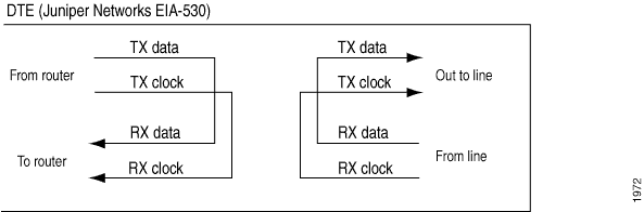
ルーターから、リモート ライン インターフェイス ユニット(LIU)ループバックは、TX(送信)データと TX クロックを RX(受信)データと RX クロックとしてルーターにループバックします。 図2に示すように、LIUループバックはラインからRXデータをループし、RXクロックはTXデータとTXクロックとしてラインをバックアウトします。
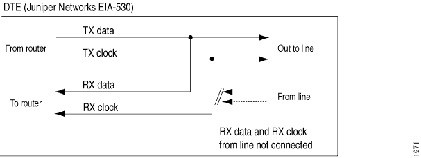
DCEローカルおよびDCEリモート制御EIA-530インターフェイス固有の信号を制御して、リンクパートナーDCEでローカルおよびリモートのループバックを有効にします。ローカルループバックを 図3に示します。
EIA-530インターフェイスでは、DCEローカル、DCEリモート、ローカル、リモート(LIU)ループバック機能を設定できます。
V.35では、リモートLIUとローカルループバック機能を設定できます。DCEローカルおよびDCEリモートループバックは、V.35およびX.21インターフェイスではサポートされていません。ローカルおよびリモートのループバックは、X.21インターフェイスではサポートされていません。
シリアルインターフェイスでループバック機能を設定するには、dce-local、dce-remote、local、またはremoteオプションを指定するloopbackステートメントを含めます。
loopback mode;
以下の階層レベルでこのステートメントを含めることができます。
-
[edit interfaces se-pim/0/port serial-options] -
[edit interfaces se-fpc/pic/port serial-options]
ループバック機能を無効にするには、設定から loopback ステートメントを削除します。
[edit]
user@host# delete interfaces se-fpc/pic/port serial-options loopback
show interface se-fpc/pic/port extensiveコマンドの出力にあるエラー カウンターを確認することで、内部または外部の問題があるかどうかを判断できます。
user@host> show interfaces se-fpc/pic/port extensive
シリアルループバック機能を設定するには:
シリアル回線エンコーディングの設定
デフォルトでは、シリアルインターフェイスはNRZ(Non-Return to Zero)ラインエンコーディングを使用します。必要に応じて、NRZI(Non-Return to Zero Inverted)ラインエンコーディングを設定できます。
インターフェイスに NRZI 行エンコーディングを使用するようにするには、nrzi オプションを指定して encoding ステートメントを含めます。
encoding nrzi;
デフォルトのNRZ行エンコーディングを明示的に設定するには、nrzオプションを指定するencodingステートメントを含めます。
encoding nrz;
以下の階層レベルでこのステートメントを含めることができます。
-
[edit interfaces se-pim/0/port serial-options] -
[edit interfaces se-fpc/pic/port serial-options]
回線エンコーディングパラメーターを設定する場合、ペアリングポートに同じ値を設定する必要があります。ポート0とポート1は同じ値を共有する必要があります。
SRXデバイスでシリアルインターフェイスを設定する
この例では、シリアルインターフェイスの初期設定を完了する方法、シリアルインターフェイスを削除する方法、シリアルインターフェイス8ポート同期シリアルGPIMの設定方法を学習します。
SRXシリーズファイアウォールへのシリアルPIMのインストールについては、 支社/拠点物理インターフェイスモジュールハードウェアガイド用のSRXシリーズファイアウォールを参照してください。
この例では:
-
シリアルインターフェイス
se-1/0/0に新しいインターフェイスを作成します。 -
カプセル化タイプをpppに設定し、
se-1/0/0の基本設定を作成します。 -
論理インターフェイスを 0 に設定すると、論理ユニット番号の範囲は 0 から 16,384 までです。
-
論理カプセル化やプロトコルファミリーなど、論理インターフェイスで設定する必要があるプロパティの追加値を入力します。
-
se-1/0/0でIPv4アドレスを10.10.10.10/24に設定します。
se-1/0/0インターフェイスを削除すると、インターフェイスは無効になり、ソフトウェア設定から削除されます。ネットワークインターフェイスは物理的に存在し、その識別子は引き続きJ-Webページに表示されます。
基本的なシリアルインターフェイス設定
この例では、se-1/0/0と呼ばれるシリアルインターフェイスを作成し、カプセル化タイプをpppに設定します。この例を迅速に設定するには、 [edit] 階層レベルでCLIクイック設定を使用し、設定モードからコミットします。
set interfaces se-1/0/0 encapsulation ppp unit 0 family inet address 10.10.10.10/24
シリアル インターフェイスを設定するには、 se-1/0/0します。
設定が正常に完了したら、 show interfaces se-1/0/0 コマンドを使用してパラメーターを表示します。
シリアル インターフェイスの削除
この例では、シリアルインターフェイス se-1/0/0を削除します。インターフェイスを設定する前に、デバイス初期化以降の設定を行う必要はありません。
シリアル インターフェイスを削除するには、 se-1/0/0します。
設定が正常に完了したら、 show interfaces コマンドを使用して設定を確認します。
例:8ポート同期シリアルGPIMでシリアルインターフェイスを設定する
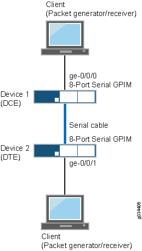
この例では、8ポート同期シリアルGPIMを使用して、基本的なバックツーバックデバイス設定を実行できます。デバイスは、データ通信機器(DCE)とデータ端末機器(DTE)の両方として表示されます。特定の導入シナリオでは、DTE はシリアル モデム、暗号化器または復号化器になります。
このシナリオでは、2つのインターフェイスを使用してシリアルインターフェイスを設定できます。Cisco HDLC(High-Level Data Link Control)、フレームリレー、PPP(Point-to-Point Protocol)など、異なるカプセル化ですべてのポートを設定できます。フレームリレーを設定した場合、データリンク接続識別子(この例では111)も設定する必要があります。デバイス1(SRX650)の8つのポートはすべてDTEモードで設定され、デバイス2(SRX650)のそれぞれ8つのポートはDCEモードで設定されます。
この例では、デバイス1の場合:
-
カプセル化タイプを
pppに設定し、論理インターフェイスを0に設定します。論理ユニット番号の範囲は0から16,384です。 -
論理カプセル化やプロトコルファミリーなど、論理インターフェイスで設定する必要があるプロパティの追加値を入力します。
-
シリアルポートでIPv4アドレスを10.10.10.1/24に設定します。
デバイス 2 の場合、デバイス 1 と同様の手順に従いますが、クロッキング モードを dce に設定します。
図4 は、この例で使用されているトポロジーを示しています。
この例を迅速に設定するには、 [edit] 階層レベルでCLIします。
デバイス1
set interfaces se-7/0/0 mtu 9192set interfaces se-7/0/0 encapsulation pppset interfaces se-7/0/0 serial-options clocking-mode internalset interfaces se-7/0/0 unit 0 family inet address 10.10.10.1/24set interfaces se-7/0/1 mtu 9192set interfaces se-7/0/1 encapsulation cisco-hdlcset interfaces se-7/0/1 serial-options clocking-mode internalset interfaces se-7/0/1 unit 0 family inet address 11.11.11.1/24set interfaces se-7/0/2 dceset interfaces se-7/0/2 mtu 9192set interfaces se-7/0/2 encapsulation frame-relayset interfaces se-7/0/2 serial-options clocking-mode internalset interfaces se-7/0/2 unit 0 dlci 111set interfaces se-7/0/2 unit 0 family inet address 12.12.12.1/24set interfaces se-7/0/3 mtu 9192set interfaces se-7/0/3 encapsulation pppset interfaces se-7/0/3 serial-options clocking-mode internalset interfaces se-7/0/3 unit 0 family inet address 13.13.13.1/24set interfaces se-7/0/4 mtu 9192set interfaces se-7/0/4 encapsulation cisco-hdlcset interfaces se-7/0/4 serial-options clocking-mode internalset interfaces se-7/0/4 unit 0 family inet address 14.14.14.1/24set interfaces se-7/0/5 dceset interfaces se-7/0/5 mtu 9192set interfaces se-7/0/5 encapsulation frame-relayset interfaces se-7/0/5 serial-options clocking-mode internalset interfaces se-7/0/5 unit 0 dlci 112set interfaces se-7/0/5 unit 0 family inet address 15.15.15.1/24set interfaces se-7/0/6 mtu 9192set interfaces se-7/0/6 encapsulation cisco-hdlcset interfaces se-7/0/6 serial-options clocking-mode internalset interfaces se-7/0/6 unit 0 family inet address 16.16.16.1/24set interfaces se-7/0/7 mtu 9192set interfaces se-7/0/7 encapsulation pppset interfaces se-7/0/7 serial-options clocking-mode internalset interfaces se-7/0/7 unit 0 family inet address 17.17.17.1/24set routing-options static route 21.21.21.0/24 next-hop 10.10.10.2set routing-options static route 23.23.23.0/24 next-hop 11.11.11.2set routing-options static route 25.25.25.0/24 next-hop 12.12.12.2set routing-options static route 27.27.27.0/24 next-hop 13.13.13.2set routing-options static route 29.29.29.0/24 next-hop 14.14.14.2set routing-options static route 31.31.31.0/24 next-hop 15.15.15.2set routing-options static route 33.33.33.0/24 next-hop 16.16.16.2set routing-options static route 35.35.35.0/24 next-hop 17.17.17.2
デバイス2
set interfaces se-3/0/0 mtu 9192set interfaces se-3/0/0 encapsulation pppset interfaces se-3/0/0 serial-options clocking-mode dceset interfaces se-3/0/0 unit 0 family inet address 10.10.10.2/24set interfaces se-3/0/1 mtu 9192set interfaces se-3/0/1 encapsulation cisco-hdlcset interfaces se-3/0/1 serial-options clocking-mode dceset interfaces se-3/0/1 unit 0 family inet address 11.11.11.2/24set interfaces se-3/0/2 dceset interfaces se-3/0/2 mtu 9192set interfaces se-3/0/2 encapsulation frame-relayset interfaces se-3/0/2 serial-options clocking-mode dceset interfaces se-3/0/2 unit 0 dlci 111set interfaces se-3/0/2 unit 0 family inet address 12.12.12.2/24set interfaces se-3/0/3 mtu 9192set interfaces se-3/0/3 encapsulation pppset interfaces se-3/0/3 serial-options clocking-mode dceset interfaces se-3/0/3 unit 0 family inet address 13.13.13.2/24set interfaces se-3/0/4 mtu 9192set interfaces se-3/0/4 encapsulation cisco-hdlcset interfaces se-3/0/4 serial-options clocking-mode dceset interfaces se-3/0/4 unit 0 family inet address 14.14.14.2/24set interfaces se-3/0/5 dceset interfaces se-3/0/5 mtu 9192set interfaces se-3/0/5 encapsulation frame-relayset interfaces se-3/0/5 serial-options clocking-mode dceset interfaces se-3/0/5 unit 0 dlci 112set interfaces se-3/0/5 unit 0 family inet address 15.15.15.2/24set interfaces se-3/0/6 mtu 9192set interfaces se-3/0/6 encapsulation cisco-hdlcset interfaces se-3/0/6 serial-options clocking-mode dceset interfaces se-3/0/6 unit 0 family inet address 16.16.16.2/24set interfaces se-3/0/7 mtu 9192set interfaces se-3/0/7 encapsulation pppset interfaces se-3/0/7 serial-options clocking-mode dceset interfaces se-3/0/7 unit 0 family inet address 17.17.17.2/24set routing-options static route 20.20.20.0/24 next-hop 10.10.10.1set routing-options static route 22.22.22.0/24 next-hop 11.11.11.1set routing-options static route 24.24.24.0/24 next-hop 12.12.12.1set routing-options static route 26.26.26.0/24 next-hop 13.13.13.1set routing-options static route 28.28.28.0/24 next-hop 14.14.14.1set routing-options static route 30.30.30.0/24 next-hop 15.15.15.1set routing-options static route 32.32.32.0/24 next-hop 16.16.16.1set routing-options static route 34.34.34.0/24 next-hop 17.17.17.1
デバイス1でインターフェイスを設定するには:
デバイス2のインターフェイスを設定するには:
-
インターフェイスの MTU 値を指定します。
[edit interfaces] user@host#
set se-3/0/0 mtu 9192 -
カプセル化タイプを設定します。
[edit interfaces] user@host#
set se-3/0/0 encapsulation ppp -
クロッキングモードなどのシリアルオプションを設定します。
[edit interfaces] user@host#
set se-3/0/0 serial-options clocking-mode dce -
シリアルポートにIPv4アドレスを設定します。
[edit interfaces] user@host#
set se-3/0/0 unit 0 family inet address 10.10.10.2/24 -
静的ルート情報を指定します。
[edit routing-options] user@host#
set static route 20.20.20.0/24 next-hop 10.10.10.1デバイス2の他の7つのポートについても同じ設定を繰り返します。
-
デバイスの設定が完了したら、設定をコミットします。
[edit]
user@host# commit
検証
目的
シリアルインターフェイスに設定されたパラメータに関する情報を表示します。
アクション
-
ネットワーク内の各ピアアドレスでpingツールを使用して、デバイス上のすべてのインターフェイスが動作していることを確認できます。すべてのインターフェイスのリンク状態を検証するには:
デバイス上の各インターフェイスについて:
-
J-Webインターフェイスで、[
Troubleshoot > Ping Host]を選択します。 -
リモートホストボックスに、リンク状態を検証するインターフェイスのアドレスを入力します。
-
Startをクリックします。出力は別のページに表示されます。
PING 10.10.10.10 : 56 data bytes
64 bytes from 10.10.10.10: icmp_seq=0 ttl=255 time=0.382 ms
64 bytes from 10.10.10.10: icmp_seq=1 ttl=255 time=0.266 ms
インターフェイスが動作している場合、ICMP応答を生成します。この応答を受信した場合、往復時間(ミリ秒単位)が時間フィールドに記載されます。
-
-
インターフェイスのプロパティが正しいことを確認するには、
show interfaces detailコマンドを使用してインターフェイス情報の概要を表示します。次の情報を確認します。-
物理インターフェイスが有効になっています。インターフェイスが無効と表示されている場合は、以下のいずれかを実行します。
-
CLI設定エディターで、設定階層の[edit interfaces se-1/0/0]レベルで
disableステートメントを削除します。 -
J-Web設定エディターで、インターフェイス>se-1/0/0ページの
Disableチェックボックスをオフにします。
-
-
物理リンクはアップです。リンク状態がダウンしている場合は、インターフェイスモジュール、インターフェイスポート、または物理接続に問題があることを示します(リンク層エラー)。
-
「最終フラップ時刻」は予想値です。これは、物理インターフェイスが最後に使用できなくなり、その後再び使用可能になった時間を示します。予期しないフラッピングは、リンク層エラーの可能性を示します。
-
トラフィック統計には、予想される入出力レートが反映されています。インバウンドおよびアウトバウンドのバイト数とパケット数が、物理インターフェイスの予想されるススループットと一致していることを確認します。統計をクリアして新しい変更のみを表示するには、
clear interfaces statistics se-1/0/0コマンドを使用します。
-
-
インターフェイスリンクのステータスがアップであることを確認するには、
show interface terse se-7/0/*コマンドを入力します。user@srx650-1>
show interface terse se-7/0/*Interface Admin Link Proto Local Remote se-7/0/0 up up se-7/0/0.0 up up inet 10.10.10.1/24 se-7/0/1 up up se-7/0/1.0 up up inet 11.11.11.1/24 se-7/0/2 up up se-7/0/2.0 up up inet 12.12.12.1/24 se-7/0/3 up up se-7/0/3.0 up up inet 13.13.13.1/24 se-7/0/4 up up se-7/0/4.0 up up inet 14.14.14.1/24 se-7/0/5 up up se-7/0/5.0 up up inet 15.15.15.1/24 se-7/0/6 up up se-7/0/6.0 up up inet 16.16.16.1/24 se-7/0/7 up up se-7/0/7.0 up up inet 17.17.17.1/24
出力には、設定されたすべてのインターフェイスのリストが表示されます。リンク列にすべてのインターフェイスの
upが表示されている場合、設定は正しいです。これにより、GPIMが稼働しており、エンドツーエンドのpingが機能していることが検証されます。 -
DCEのインターフェイス統計を確認するには、
show interface se-7/0/0 extensive | no-moreコマンドを使用します。user@srx650-1>
show interface se-7/0/0 extensive | no-morePhysical interface: se-7/0/0, Enabled, Physical link is Up Interface index: 161, SNMP ifIndex: 592, Generation: 164 Type: Serial, Link-level type: PPP, MTU: 1504, Maximum speed: 8mbps Device flags : Present Running Interface flags: Point-To-Point Internal: 0x0 Link flags : Keepalives Hold-times : Up 0 ms, Down 0 ms Keepalive settings: Interval 10 seconds, Up-count 1, Down-count 3 Keepalive statistics: Input : 123 (last seen 00:00:02 ago) Output: 123 (last sent 00:00:01 ago) LCP state: Opened NCP state: inet: Opened, inet6: Not-configured, iso: Not-configured, mpls: Not-configured CHAP state: Closed PAP state: Closed CoS queues : 8 supported, 8 maximum usable queues Last flapped : 2011-06-27 22:57:24 PDT (00:20:59 ago) Statistics last cleared: Never Traffic statistics: Input bytes : 23792 160 bps Output bytes : 22992 536 bps Input packets: 404 0 pps Output packets: 409 0 pps Input errors: Errors: 3, Drops: 0, Framing errors: 3, Runts: 0, Giants: 0, Policed discards: 0, Resource errors: 0 Output errors: Carrier transitions: 1, Errors: 0, Drops: 0, MTU errors: 0, Resource errors: 0 Egress queues: 8 supported, 4 in use Queue counters: Queued packets Transmitted packets Dropped packets 0 best-effort 0 0 0 1 expedited-fo 0 0 0 2 assured-forw 0 0 0 3 network-cont 409 409 0 Queue number: Mapped forwarding classes 0 best-effort 1 expedited-forwarding 2 assured-forwarding 3 network-control Serial media information: Line protocol: eia530 Resync history: Sync loss count: 0 Data signal: Rx Clock: OK Control signals: Local mode: DCE To DTE: CTS: up, DCD: up, DSR: up From DTE: DTR: up, RTS: up DCE loopback override: Off Clocking mode: internal Loopback: none Tx clock: non-invert Line encoding: nrz Packet Forwarding Engine configuration: Destination slot: 7 CoS information: Direction : Output CoS transmit queue Bandwidth Buffer Priority Limit % bps % usec 0 best-effort 95 7600000 95 0 low none 3 network-control 5 400000 5 0 low none continue................................................................................ ..........................................................................................出力には、すべての DCE 検証パラメーターと設定されたモードのリストが表示されます。ローカルモードにDCEが表示されている場合、設定は正しいです。
-
DTEのインターフェイス統計を確認するには、
show interface se-3/0/0 extensive | no-moreコマンドを使用します。user@srx650-2>
show interfaces se-3/0/0 extensive | no-morePhysical interface: se-3/0/0, Enabled, Physical link is Up Interface index: 168, SNMP ifIndex: 594, Generation: 171 Type: Serial, Link-level type: PPP, MTU: 1504, Maximum speed: 8mbps Device flags : Present Running Interface flags: Point-To-Point Internal: 0x0 Link flags : Keepalives Hold-times : Up 0 ms, Down 0 ms Keepalive settings: Interval 10 seconds, Up-count 1, Down-count 3 Keepalive statistics: Input : 242 (last seen 00:00:09 ago) Output: 242 (last sent 00:00:10 ago) LCP state: Opened NCP state: inet: Opened, inet6: Not-configured, iso: Not-configured, mpls: Not-configured CHAP state: Closed PAP state: Closed CoS queues : 8 supported, 8 maximum usable queues Last flapped : 2011-06-27 22:52:06 PDT (00:40:41 ago) Statistics last cleared: Never Traffic statistics: Input bytes : 44582 0 bps Output bytes : 42872 0 bps Input packets: 776 0 pps Output packets: 779 0 pps Input errors: Errors: 6, Drops: 0, Framing errors: 6, Runts: 0, Giants: 0, Policed discards: 0, Resource errors: 0 Output errors: Carrier transitions: 1, Errors: 0, Drops: 0, MTU errors: 0, Resource errors: 0 Egress queues: 8 supported, 4 in use Queue counters: Queued packets Transmitted packets Dropped packets 0 best-effort 2 2 0 1 expedited-fo 0 0 0 2 assured-forw 0 0 0 3 network-cont 777 777 0 Queue number: Mapped forwarding classes 0 best-effort 1 expedited-forwarding 2 assured-forwarding 3 network-control Serial media information: Line protocol: eia530 Resync history: Sync loss count: 0 Data signal: Rx Clock: OK Control signals: Local mode: DTE To DCE: DTR: up, RTS: up From DCE: CTS: up, DCD: up, DSR: up Clocking mode: loop-timed Loopback: none Tx clock: non-invert Line encoding: nrz Packet Forwarding Engine configuration: Destination slot: 3 CoS information: Direction : Output CoS transmit queue Bandwidth Buffer Priority Limit % bps % usec 0 best-effort 95 7600000 95 0 low none 3 network-control 5 400000 5 0 low none continue ........................................................................... .....................................................................................出力には、すべてのDTE検証パラメーターと設定されたモードのリストが表示されます。ローカルモードにDTEが表示されている場合、設定は正しいです。