例:MXルーターをスパインとして使用して、EVPN-VXLAN集中型ルーテッドブリッジングファブリックを設定します。
この例では、IPファブリック上にEVPNとVXLANを設定し、イーサネットフレームの最適な転送をサポートし、広範囲にネットワークをセグメント化し、コントロールプレーンベースのMAC学習を可能にするなど、多くの利点を得る方法を示します。この例は、5ステージClosファブリックにおけるCRB(Centrally-Routed with Bridging)EVPNアーキテクチャに基づいています。
CRB アーキテクチャでは、IRB インターフェイスは、異なる VLAN やネットワークに属するサーバーや VM へのレイヤー 3 接続を提供します。これらのIRBインターフェイスは、ファブリック内のVLAN間トラフィックのデフォルトゲートウェイとして機能し、例えばデータセンターの相互接続(DCI)の場合、ファブリックから離れた宛先のデフォルトゲートウェイとしても機能します。CRB 設計では、スパイン デバイスのみで IRB インターフェイスを定義します。したがって、このような設計は、すべてのルーティングがスパインで行われるため、中央ルーティングと呼ばれます。
ERB(エッジルーテッドブリッジング)設計の例については、例を参照してください: エニーキャストゲートウェイを使用したEVPN-VXLANエッジルーテッドブリッジングファブリックの設定
EVPN-VXLANテクノロジーとサポートされているアーキテクチャの背景情報については、 EVPN入門を参照してください。
要件
元の例では、以下のハードウェアおよびソフトウェアコンポーネントを使用しました。
-
EVPNオーバーレイのIPゲートウェイとして機能する2台のジュニパーネットワークスMXシリーズルーター
-
ジュニパーネットワークス QFX5100 スイッチ 4 台。これらのスイッチのうちの 2 つは EVPN トポロジーで PE デバイスとして機能し、他の 2 つのスイッチはアンダーレイの純粋な IP トランスポートとして機能します。
-
Junos OSリリース21.3R1以降。
-
この例では、EX9200スイッチをEVPNオーバーレイのIPゲートウェイとして機能させることができます。MXシリーズルーターとEX9200スイッチでは、いくつかの構成上の違いがあります。このトピックで後述する設定セクションでは、EX9200に固有の設定について詳しく説明します。
- サポートされているプラットフォームのリストについては、 ハードウェアの概要 を参照してください。
概要
EVPN(イーサネット VPN)により、レイヤー 2 の仮想ブリッジを使用して分散した顧客サイトのグループに接続でき、VXLAN(仮想拡張 LAN)により、レイヤー 2 接続をレイヤー 3 ネットワークを介して拡張し、VLAN のようなネットワークのセグメント化を、従来の VLAN のような拡張制限なしで実現できます。VXLANカプセル化を備えたEVPNは、クラウドサービスプロバイダが必要とする規模でレイヤー2接続を処理し、STPなどの制限プロトコルを置き換えることで、レイヤー3ネットワークでより堅牢なルーティングプロトコルを使用できるようになります。
この設定例では、VXLAN カプセル化を使用して EVPN を設定する方法を示しています。この例では、MXシリーズルーターの名前はCore-1とCore-2です。QFX5100スイッチの名前は、リーフ1、リーフ2、スパイン1、およびスパイン2です。コアルーターはEVPNオーバーレイのIPゲートウェイとして機能し、リーフスイッチはEVPNトポロジーのPEデバイスとして機能し、スパインスイッチはアンダーレイの純粋なIPトランスポート(「リーンスパイン」とも呼ばれます)として機能します。
トポロジー
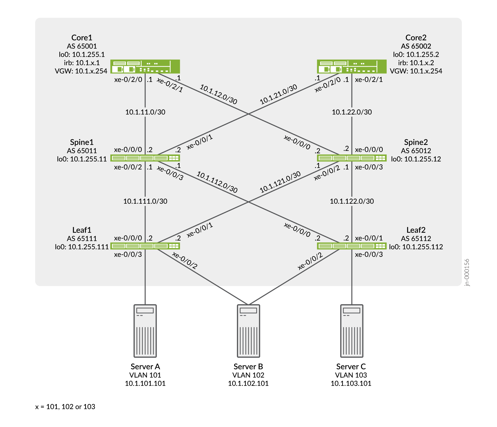
サンプルトポロジーでは、タグなしインターフェイスとトランク(タグ付き)インターフェイスの両方を使用したサーバーアクセスを示しています。トランク インターフェイスは、明示的な VLAN タグを使用します。サーバーAとCの両方がトランキング用に設定されていますが、サーバーBは両方のリーフに対してタグなしアクセスインターフェイスを使用します。
設定
CLIクイックコンフィグレーション
この例をすばやく設定するには、以下のコマンドをコピーしてテキストファイルに貼り付け、改行を削除して、ネットワーク構成に合わせて必要な詳細を変更してから、コマンドを [edit] 階層レベルのCLIにコピー&ペーストします。
リーフ-1
set system host-name leaf-1
set chassis aggregated-devices ethernet device-count 2
set interfaces xe-0/0/0 unit 0 family inet address 10.1.111.2/30
set interfaces xe-0/0/1 unit 0 family inet address 10.1.121.2/30
set interfaces xe-0/0/2 ether-options 802.3ad ae0
set interfaces xe-0/0/3 unit 0 family ethernet-switching interface-mode trunk
set interfaces xe-0/0/3 unit 0 family ethernet-switching vlan members v101
set interfaces ae0 esi 00:01:01:01:01:01:01:01:01:01
set interfaces ae0 esi all-active
set interfaces ae0 aggregated-ether-options lacp active
set interfaces ae0 aggregated-ether-options lacp system-id 00:00:00:01:01:01
set interfaces ae0 unit 0 family ethernet-switching interface-mode access
set interfaces ae0 unit 0 family ethernet-switching vlan members v102
set interfaces lo0 unit 0 family inet address 10.1.255.111/32
set policy-options policy-statement lo0 from family inet
set policy-options policy-statement lo0 from protocol direct
set policy-options policy-statement lo0 from route-filter 0.0.0.0/0 prefix-length-range /32-/32
set policy-options policy-statement lo0 then accept
set policy-options policy-statement load-balance term 1 then load-balance per-packet
set policy-options policy-statement vrf-imp term t1 from community com101
set policy-options policy-statement vrf-imp term t1 then accept
set policy-options policy-statement vrf-imp term t2 from community com102
set policy-options policy-statement vrf-imp term t2 then accept
set policy-options policy-statement vrf-imp term t3 from community com103
set policy-options policy-statement vrf-imp term t3 then accept
set policy-options policy-statement vrf-imp term t5 then reject
set policy-options community com101 members target:65000:101
set policy-options community com102 members target:65000:102
set policy-options community com103 members target:65000:103
set routing-options router-id 10.1.255.111
set routing-options autonomous-system 65000
set routing-options forwarding-table export load-balance
set routing-options forwarding-table ecmp-fast-reroute
set protocols bgp group underlay type external
set protocols bgp group underlay export lo0
set protocols bgp group underlay local-as 65111
set protocols bgp group underlay multipath multiple-as
set protocols bgp group underlay neighbor 10.1.111.1 peer-as 65011
set protocols bgp group underlay neighbor 10.1.121.1 peer-as 65012
set protocols bgp group EVPN_VXLAN_CORE type internal
set protocols bgp group EVPN_VXLAN_CORE local-address 10.1.255.111
set protocols bgp group EVPN_VXLAN_CORE family evpn signaling
set protocols bgp group EVPN_VXLAN_CORE neighbor 10.1.255.1
set protocols bgp group EVPN_VXLAN_CORE neighbor 10.1.255.2
set protocols evpn encapsulation vxlan
set protocols evpn multicast-mode ingress-replication
set protocols evpn vni-options vni 101 vrf-target target:65000:101
set protocols evpn vni-options vni 102 vrf-target target:65000:102
set protocols evpn extended-vni-list 101
set protocols evpn extended-vni-list 102
set switch-options vtep-source-interface lo0.0
set switch-options route-distinguisher 10.1.255.111:1
set switch-options vrf-import vrf-imp
set switch-options vrf-target target:65000:1
set vlans v101 vlan-id 101
set vlans v101 vxlan vni 101
set vlans v102 vlan-id 102
set vlans v102 vxlan vni 102
リーフ-2
set system host-name leaf-2
set chassis aggregated-devices ethernet device-count 2
set interfaces xe-0/0/0 unit 0 family inet address 10.1.112.2/30
set interfaces xe-0/0/1 unit 0 family inet address 10.1.122.2/30
set interfaces xe-0/0/2 ether-options 802.3ad ae0
set interfaces xe-0/0/3 unit 0 family ethernet-switching interface-mode trunk
set interfaces xe-0/0/3 unit 0 family ethernet-switching vlan members v103
set interfaces ae0 esi 00:01:01:01:01:01:01:01:01:01
set interfaces ae0 esi all-active
set interfaces ae0 aggregated-ether-options lacp active
set interfaces ae0 aggregated-ether-options lacp system-id 00:00:00:01:01:01
set interfaces ae0 unit 0 family ethernet-switching interface-mode access
set interfaces ae0 unit 0 family ethernet-switching vlan members v102
set interfaces lo0 unit 0 family inet address 10.1.255.112/32
set policy-options policy-statement lo0 from family inet
set policy-options policy-statement lo0 from protocol direct
set policy-options policy-statement lo0 from route-filter 0.0.0.0/0 prefix-length-range /32-/32
set policy-options policy-statement lo0 then accept
set policy-options policy-statement load-balance term 1 then load-balance per-packet
set policy-options policy-statement vrf-imp term t1 from community com101
set policy-options policy-statement vrf-imp term t1 then accept
set policy-options policy-statement vrf-imp term t2 from community com102
set policy-options policy-statement vrf-imp term t2 then accept
set policy-options policy-statement vrf-imp term t3 from community com103
set policy-options policy-statement vrf-imp term t3 then accept
set policy-options policy-statement vrf-imp term t5 then reject
set policy-options community com101 members target:65000:101
set policy-options community com102 members target:65000:102
set policy-options community com103 members target:65000:103
set routing-options router-id 10.1.255.112
set routing-options autonomous-system 65000
set routing-options forwarding-table export load-balance
set routing-options forwarding-table ecmp-fast-reroute
set protocols bgp group underlay type external
set protocols bgp group underlay export lo0
set protocols bgp group underlay local-as 65112
set protocols bgp group underlay multipath multiple-as
set protocols bgp group underlay neighbor 10.1.112.1 peer-as 65011
set protocols bgp group underlay neighbor 10.1.122.1 peer-as 65012
set protocols bgp group EVPN_VXLAN_CORE type internal
set protocols bgp group EVPN_VXLAN_CORE local-address 10.1.255.112
set protocols bgp group EVPN_VXLAN_CORE family evpn signaling
set protocols bgp group EVPN_VXLAN_CORE neighbor 10.1.255.1
set protocols bgp group EVPN_VXLAN_CORE neighbor 10.1.255.2
set protocols evpn encapsulation vxlan
set protocols evpn multicast-mode ingress-replication
set protocols evpn vni-options vni 102 vrf-target target:65000:102
set protocols evpn vni-options vni 103 vrf-target target:65000:103
set protocols evpn extended-vni-list 102
set protocols evpn extended-vni-list 103
set switch-options vtep-source-interface lo0.0
set switch-options route-distinguisher 10.1.255.112:1
set switch-options vrf-import vrf-imp
set switch-options vrf-target target:65000:1
set vlans v102 vlan-id 102
set vlans v102 vxlan vni 102
set vlans v103 vlan-id 103
set vlans v103 vxlan vni 103
スパイン-1
set system host-name spine-1
set interfaces xe-0/0/0 unit 0 family inet address 10.1.11.2/30
set interfaces xe-0/0/1 unit 0 family inet address 10.1.21.2/30
set interfaces xe-0/0/2 unit 0 family inet address 10.1.111.1/30
set interfaces xe-0/0/3 unit 0 family inet address 10.1.112.1/30
set interfaces lo0 unit 0 family inet address 10.1.255.11/32
set policy-options policy-statement lo0 from family inet
set policy-options policy-statement lo0 from protocol direct
set policy-options policy-statement lo0 from route-filter 0.0.0.0/0 prefix-length-range /32-/32
set policy-options policy-statement lo0 then accept
set policy-options policy-statement load-balance term 1 then load-balance per-packet
set routing-options router-id 10.1.255.11
set routing-options autonomous-system 65000
set routing-options forwarding-table export load-balance
set routing-options forwarding-table ecmp-fast-reroute
set protocols bgp group underlay type external
set protocols bgp group underlay export lo0
set protocols bgp group underlay local-as 65011
set protocols bgp group underlay multipath multiple-as
set protocols bgp group underlay neighbor 10.1.11.1 peer-as 65001
set protocols bgp group underlay neighbor 10.1.21.1 peer-as 65002
set protocols bgp group underlay neighbor 10.1.111.2 peer-as 65111
set protocols bgp group underlay neighbor 10.1.112.2 peer-as 65112
スパイン-2
set system host-name spine-2
set interfaces xe-0/0/0 unit 0 family inet address 10.1.12.2/30
set interfaces xe-0/0/1 unit 0 family inet address 10.1.22.2/30
set interfaces xe-0/0/2 unit 0 family inet address 10.1.121.1/30
set interfaces xe-0/0/3 unit 0 family inet address 10.1.122.1/30
set interfaces lo0 unit 0 family inet address 10.1.255.12/32
set policy-options policy-statement lo0 from family inet
set policy-options policy-statement lo0 from protocol direct
set policy-options policy-statement lo0 from route-filter 0.0.0.0/0 prefix-length-range /32-/32
set policy-options policy-statement lo0 then accept
set policy-options policy-statement load-balance term 1 then load-balance per-packet
set routing-options router-id 10.1.255.12
set routing-options autonomous-system 65000
set routing-options forwarding-table export load-balance
set routing-options forwarding-table ecmp-fast-reroute
set protocols bgp group underlay type external
set protocols bgp group underlay export lo0
set protocols bgp group underlay local-as 65012
set protocols bgp group underlay multipath multiple-as
set protocols bgp group underlay neighbor 10.1.12.1 peer-as 65001
set protocols bgp group underlay neighbor 10.1.22.1 peer-as 65002
set protocols bgp group underlay neighbor 10.1.121.2 peer-as 65111
set protocols bgp group underlay neighbor 10.1.122.2 peer-as 65112
コア-1
set system host-name core-1
set interfaces xe-0/2/0 unit 0 family inet address 10.1.11.1/30
set interfaces xe-0/2/1 unit 0 family inet address 10.1.12.1/30
set interfaces irb unit 101 virtual-gateway-accept-data
set interfaces irb unit 101 family inet address 10.1.101.1/24 virtual-gateway-address 10.1.101.254
set interfaces irb unit 102 virtual-gateway-accept-data
set interfaces irb unit 102 family inet address 10.1.102.1/24 virtual-gateway-address 10.1.102.254
set interfaces irb unit 103 virtual-gateway-accept-data
set interfaces irb unit 103 family inet address 10.1.103.1/24 virtual-gateway-address 10.1.103.254
set interfaces lo0 unit 0 family inet address 10.1.255.1/32
set policy-options policy-statement VS_VLAN101_IMP term ESI from community comm-leaf
set policy-options policy-statement VS_VLAN101_IMP term ESI then accept
set policy-options policy-statement VS_VLAN101_IMP term VS_VLAN101 from community comm-VS_VLAN101
set policy-options policy-statement VS_VLAN101_IMP term VS_VLAN101 then accept
set policy-options policy-statement VS_VLAN102_IMP term ESI from community comm-leaf
set policy-options policy-statement VS_VLAN102_IMP term ESI then accept
set policy-options policy-statement VS_VLAN102_IMP term VS_VLAN102 from community comm-VS_VLAN102
set policy-options policy-statement VS_VLAN102_IMP term VS_VLAN102 then accept
set policy-options policy-statement VS_VLAN103_IMP term ESI from community comm-leaf
set policy-options policy-statement VS_VLAN103_IMP term ESI then accept
set policy-options policy-statement VS_VLAN103_IMP term VS_VLAN103 from community comm-VS_VLAN103
set policy-options policy-statement VS_VLAN103_IMP term VS_VLAN103 then accept
set policy-options policy-statement lo0 from family inet
set policy-options policy-statement lo0 from protocol direct
set policy-options policy-statement lo0 from route-filter 0.0.0.0/0 prefix-length-range /32-/32
set policy-options policy-statement lo0 then accept
set policy-options policy-statement load-balance term 1 then load-balance per-packet
set policy-options community comm-VS_VLAN101 members target:65000:101
set policy-options community comm-VS_VLAN102 members target:65000:102
set policy-options community comm-VS_VLAN103 members target:65000:103
set policy-options community comm-leaf members target:65000:1
set routing-instances VRF_Tenant_A instance-type vrf
set routing-instances VRF_Tenant_A interface irb.101
set routing-instances VRF_Tenant_A route-distinguisher 10.1.255.1:1010
set routing-instances VRF_Tenant_A vrf-target target:65000:101
set routing-instances VRF_Tenant_B instance-type vrf
set routing-instances VRF_Tenant_B interface irb.102
set routing-instances VRF_Tenant_B route-distinguisher 10.1.255.1:1020
set routing-instances VRF_Tenant_B vrf-target target:65000:102
set routing-instances VRF_Tenant_C instance-type vrf
set routing-instances VRF_Tenant_C interface irb.103
set routing-instances VRF_Tenant_C route-distinguisher 10.1.255.1:1030
set routing-instances VRF_Tenant_C vrf-target target:65000:103
set routing-instances VS_VLAN101 instance-type virtual-switch
set routing-instances VS_VLAN101 protocols evpn encapsulation vxlan
set routing-instances VS_VLAN101 protocols evpn extended-vni-list 101
set routing-instances VS_VLAN101 protocols evpn multicast-mode ingress-replication
set routing-instances VS_VLAN101 vtep-source-interface lo0.0
set routing-instances VS_VLAN101 bridge-domains bd101 vlan-id 101
set routing-instances VS_VLAN101 bridge-domains bd101 routing-interface irb.101
set routing-instances VS_VLAN101 bridge-domains bd101 vxlan vni 101
set routing-instances VS_VLAN101 route-distinguisher 10.1.255.1:101
set routing-instances VS_VLAN101 vrf-import VS_VLAN101_IMP
set routing-instances VS_VLAN101 vrf-target target:65000:101
set routing-instances VS_VLAN102 instance-type virtual-switch
set routing-instances VS_VLAN102 protocols evpn encapsulation vxlan
set routing-instances VS_VLAN102 protocols evpn extended-vni-list 102
set routing-instances VS_VLAN102 protocols evpn multicast-mode ingress-replication
set routing-instances VS_VLAN102 vtep-source-interface lo0.0
set routing-instances VS_VLAN102 bridge-domains bd102 vlan-id 102
set routing-instances VS_VLAN102 bridge-domains bd102 routing-interface irb.102
set routing-instances VS_VLAN102 bridge-domains bd102 vxlan vni 102
set routing-instances VS_VLAN102 route-distinguisher 10.1.255.1:102
set routing-instances VS_VLAN102 vrf-import VS_VLAN102_IMP
set routing-instances VS_VLAN102 vrf-target target:65000:102
set routing-instances VS_VLAN103 instance-type virtual-switch
set routing-instances VS_VLAN103 protocols evpn encapsulation vxlan
set routing-instances VS_VLAN103 protocols evpn extended-vni-list 103
set routing-instances VS_VLAN103 protocols evpn multicast-mode ingress-replication
set routing-instances VS_VLAN103 vtep-source-interface lo0.0
set routing-instances VS_VLAN103 bridge-domains bd103 vlan-id 103
set routing-instances VS_VLAN103 bridge-domains bd103 routing-interface irb.103
set routing-instances VS_VLAN103 bridge-domains bd103 vxlan vni 103
set routing-instances VS_VLAN103 route-distinguisher 10.1.255.1:103
set routing-instances VS_VLAN103 vrf-import VS_VLAN103_IMP
set routing-instances VS_VLAN103 vrf-target target:65000:103
set routing-options router-id 10.1.255.1
set routing-options autonomous-system 65000
set routing-options forwarding-table export load-balance
set routing-options forwarding-table ecmp-fast-reroute
set protocols bgp group underlay type external
set protocols bgp group underlay export lo0
set protocols bgp group underlay local-as 65001
set protocols bgp group underlay multipath multiple-as
set protocols bgp group underlay neighbor 10.1.11.2 peer-as 65011
set protocols bgp group underlay neighbor 10.1.12.2 peer-as 65012
set protocols bgp group EVPN_VXLAN type internal
set protocols bgp group EVPN_VXLAN local-address 10.1.255.1
set protocols bgp group EVPN_VXLAN family evpn signaling
set protocols bgp group EVPN_VXLAN cluster 10.1.1.1
set protocols bgp group EVPN_VXLAN multipath
set protocols bgp group EVPN_VXLAN neighbor 10.1.255.111
set protocols bgp group EVPN_VXLAN neighbor 10.1.255.112
set protocols bgp group EVPN_VXLAN neighbor 10.1.255.2
コア-2
set system host-name core-2
set interfaces xe-0/2/0 unit 0 family inet address 10.1.21.1/30
set interfaces xe-0/2/1 unit 0 family inet address 10.1.22.1/30
set interfaces irb unit 101 virtual-gateway-accept-data
set interfaces irb unit 101 family inet address 10.1.101.2/24 virtual-gateway-address 10.1.101.254
set interfaces irb unit 102 virtual-gateway-accept-data
set interfaces irb unit 102 family inet address 10.1.102.2/24 virtual-gateway-address 10.1.102.254
set interfaces irb unit 103 virtual-gateway-accept-data
set interfaces irb unit 103 family inet address 10.1.103.2/24 virtual-gateway-address 10.1.103.254
set interfaces lo0 unit 0 family inet address 10.1.255.2/32
set policy-options policy-statement VS_VLAN101_IMP term ESI from community comm-leaf
set policy-options policy-statement VS_VLAN101_IMP term ESI then accept
set policy-options policy-statement VS_VLAN101_IMP term VS_VLAN101 from community comm-VS_VLAN101
set policy-options policy-statement VS_VLAN101_IMP term VS_VLAN101 then accept
set policy-options policy-statement VS_VLAN102_IMP term ESI from community comm-leaf
set policy-options policy-statement VS_VLAN102_IMP term ESI then accept
set policy-options policy-statement VS_VLAN102_IMP term VS_VLAN102 from community comm-VS_VLAN102
set policy-options policy-statement VS_VLAN102_IMP term VS_VLAN102 then accept
set policy-options policy-statement VS_VLAN103_IMP term ESI from community comm-leaf
set policy-options policy-statement VS_VLAN103_IMP term ESI then accept
set policy-options policy-statement VS_VLAN103_IMP term VS_VLAN103 from community comm-VS_VLAN103
set policy-options policy-statement VS_VLAN103_IMP term VS_VLAN103 then accept
set policy-options policy-statement lo0 from family inet
set policy-options policy-statement lo0 from protocol direct
set policy-options policy-statement lo0 from route-filter 0.0.0.0/0 prefix-length-range /32-/32
set policy-options policy-statement lo0 then accept
set policy-options policy-statement load-balance term 1 then load-balance per-packet
set policy-options community comm-VS_VLAN101 members target:65000:101
set policy-options community comm-VS_VLAN102 members target:65000:102
set policy-options community comm-VS_VLAN103 members target:65000:103
set policy-options community comm-leaf members target:65000:1
set routing-instances VRF_Tenant_A instance-type vrf
set routing-instances VRF_Tenant_A interface irb.101
set routing-instances VRF_Tenant_A route-distinguisher 10.1.255.2:1010
set routing-instances VRF_Tenant_A vrf-target target:65000:101
set routing-instances VRF_Tenant_B instance-type vrf
set routing-instances VRF_Tenant_B interface irb.102
set routing-instances VRF_Tenant_B route-distinguisher 10.1.255.2:1020
set routing-instances VRF_Tenant_B vrf-target target:65000:102
set routing-instances VRF_Tenant_C instance-type vrf
set routing-instances VRF_Tenant_C interface irb.103
set routing-instances VRF_Tenant_C route-distinguisher 10.1.255.2:1030
set routing-instances VRF_Tenant_C vrf-target target:65000:103
set routing-instances VS_VLAN101 instance-type virtual-switch
set routing-instances VS_VLAN101 protocols evpn encapsulation vxlan
set routing-instances VS_VLAN101 protocols evpn extended-vni-list 101
set routing-instances VS_VLAN101 protocols evpn multicast-mode ingress-replication
set routing-instances VS_VLAN101 vtep-source-interface lo0.0
set routing-instances VS_VLAN101 bridge-domains bd101 vlan-id 101
set routing-instances VS_VLAN101 bridge-domains bd101 routing-interface irb.101
set routing-instances VS_VLAN101 bridge-domains bd101 vxlan vni 101
set routing-instances VS_VLAN101 route-distinguisher 10.1.255.2:101
set routing-instances VS_VLAN101 vrf-import VS_VLAN101_IMP
set routing-instances VS_VLAN101 vrf-target target:65000:101
set routing-instances VS_VLAN102 instance-type virtual-switch
set routing-instances VS_VLAN102 protocols evpn encapsulation vxlan
set routing-instances VS_VLAN102 protocols evpn extended-vni-list 102
set routing-instances VS_VLAN102 protocols evpn multicast-mode ingress-replication
set routing-instances VS_VLAN102 vtep-source-interface lo0.0
set routing-instances VS_VLAN102 bridge-domains bd102 vlan-id 102
set routing-instances VS_VLAN102 bridge-domains bd102 routing-interface irb.102
set routing-instances VS_VLAN102 bridge-domains bd102 vxlan vni 102
set routing-instances VS_VLAN102 route-distinguisher 10.1.255.2:102
set routing-instances VS_VLAN102 vrf-import VS_VLAN102_IMP
set routing-instances VS_VLAN102 vrf-target target:65000:102
set routing-instances VS_VLAN103 instance-type virtual-switch
set routing-instances VS_VLAN103 protocols evpn encapsulation vxlan
set routing-instances VS_VLAN103 protocols evpn extended-vni-list 103
set routing-instances VS_VLAN103 protocols evpn multicast-mode ingress-replication
set routing-instances VS_VLAN103 vtep-source-interface lo0.0
set routing-instances VS_VLAN103 bridge-domains bd103 vlan-id 103
set routing-instances VS_VLAN103 bridge-domains bd103 routing-interface irb.103
set routing-instances VS_VLAN103 bridge-domains bd103 vxlan vni 103
set routing-instances VS_VLAN103 route-distinguisher 10.1.255.2:103
set routing-instances VS_VLAN103 vrf-import VS_VLAN103_IMP
set routing-instances VS_VLAN103 vrf-target target:65000:103
set routing-options router-id 10.1.255.2
set routing-options autonomous-system 65000
set routing-options forwarding-table export load-balance
set routing-options forwarding-table ecmp-fast-reroute
set protocols bgp group underlay type external
set protocols bgp group underlay export lo0
set protocols bgp group underlay local-as 65002
set protocols bgp group underlay multipath multiple-as
set protocols bgp group underlay neighbor 10.1.21.2 peer-as 65011
set protocols bgp group underlay neighbor 10.1.22.2 peer-as 65012
set protocols bgp group EVPN_VXLAN type internal
set protocols bgp group EVPN_VXLAN local-address 10.1.255.2
set protocols bgp group EVPN_VXLAN family evpn signaling
set protocols bgp group EVPN_VXLAN cluster 10.2.2.2
set protocols bgp group EVPN_VXLAN multipath
set protocols bgp group EVPN_VXLAN neighbor 10.1.255.111
set protocols bgp group EVPN_VXLAN neighbor 10.1.255.112
set protocols bgp group EVPN_VXLAN neighbor 10.1.255.1
EX9200の設定
EX9200スイッチでは、bridge-domainsの代わりにvlansステートメントが使用され、routing-interfaceの代わりにl3-interfaceステートメントが使用されます。
以下の例は、これらのステートメントを設定する方法を示しています。この例で示したMXシリーズルーターの他のすべての設定は、EX9200スイッチにも適用されます。
set routing-instances VS_VLAN300 vlans vlan1300 vlan-id 300
set routing-instances VS_VLAN300 vlans vlan1300 l3-inteface irb.1300
この例では、 bridge-domains ステートメントまたは routing-interface ステートメントが使用される場合はどこでも、スイッチEX9200設定するには、代わりに vlans と l3-interface を使用します。
リーフ 1 の設定
ステップバイステップの手順
次の例では、設定階層のさまざまなレベルに移動する必要があります。CLIのナビゲーションについては、『CLIユーザーガイド』の「設定モードでのCLIエディターの使用」を参照してください。
リーフ 2 の設定手順はリーフ 1 と似ているため、リーフ 1 の設定手順を順を追って説明します。
リーフ 1 を設定するには:
-
システムホスト名を設定します。
[edit]
user@leaf-1# set system host-name leaf-1
-
ルーティングオプションを設定します。 load-balance エクスポートポリシーは、次のステップで設定します。
[edit]
user@leaf-1# set routing-options router-id 10.1.255.111
user@leaf-1# set routing-options autonomous-system 65000
user@leaf-1# set routing-options forwarding-table export load-balance
user@leaf-1# set routing-options forwarding-table ecmp-fast-reroute
-
ロードバランシングポリシーを設定します。
[edit policy-options policy-statement load-balance]
user@leaf-1# set term 1 then load-balance per-packet
-
スパインデバイスへのアンダーレイEBGPを設定します。 lo0 エクスポートポリシーは、次のステップで設定します。
[edit]
user@leaf-1# set protocols bgp group underlay type external
user@leaf-1# set protocols bgp group underlay export lo0
user@leaf-1# set protocols bgp group underlay local-as 65111
user@leaf-1# set protocols bgp group underlay multipath multiple-as
user@leaf-1# set protocols bgp group underlay neighbor 10.1.111.1 peer-as 65011
user@leaf-1# set protocols bgp group underlay neighbor 10.1.121.1 peer-as 65012
-
アンダーレイにループバックアドレスをアドバタイズするポリシーを設定します。この例では、プレフィックス長が /32 の直接ルートのみを一致させることで、ループバックアドレスに依存しないポータブルポリシーを記述します。その結果、任意のループバックアドレスに一致し、トポロジー内のすべてのデバイスで再利用可能なポリシーが完成します。
[edit policy-options policy-statement lo0]
user@leaf-1# set from family inet
user@leaf-1# set from protocol direct
user@leaf-1# set from route-filter 0.0.0.0/0 prefix-length-range /32-/32
user@leaf-1# set then accept
-
スイッチオプションを設定します。仮想トンネルエンドポイントインターフェイスはlo0.0で、アンダーレイルーティングプロトコルを介して到達可能である必要があります。MP-BGPオーバーレイ内のすべてのルートアドバタイズメントがグローバルに一意であることを保証するには、ネットワーク内のすべてのスイッチでルート識別子が一意である必要があります。QFXシリーズスイッチ上のVRFテーブルターゲットは、少なくとも、スイッチが送信するコミュニティがすべてのESI(タイプ1)ルートに接続することです。
vrf-import vrf-impステートメントは、ターゲットコミュニティリストを定義し、bgp.evpn.0テーブルからdefault-switch.evpn.0インスタンスにインポートされます。[edit] user@leaf-1# set switch-options vtep-source-interface lo0.0 user@leaf-1# set switch-options route-distinguisher 10.1.255.111:1 user@leaf-1# set switch-options vrf-import vrf-imp user@leaf-1# set switch-options vrf-target target:65000:1
-
VRFテーブルのインポートポリシーを設定します。
[edit]
user@leaf-1# set policy-options policy-statement vrf-imp term t1 from community com101
user@leaf-1# set policy-options policy-statement vrf-imp term t1 then accept
user@leaf-1# set policy-options policy-statement vrf-imp term t2 from community com102
user@leaf-1# set policy-options policy-statement vrf-imp term t2 then accept
user@leaf-1# set policy-options policy-statement vrf-imp term t3 from community com103
user@leaf-1# set policy-options policy-statement vrf-imp term t3 then accept
user@leaf-1# set policy-options policy-statement vrf-imp term t5 then reject
-
関連するコミュニティを設定します。
[edit]
user@leaf-1# set policy-options community com101 members target:65000:101
user@leaf-1# set policy-options community com102 members target:65000:102
user@leaf-1# set policy-options community com103 members target:65000:103
-
拡張仮想ネットワーク識別子(VNI)リストを設定して、EVPN ドメインに属させる VNI を確立します。また、イングレスレプリケーションも設定します。EVPN-VXLANでは、イングレスレプリケーションを使用して、マルチキャスト対応アンダーレイを必要とせずにマルチキャスト処理を行います。
vni-routing-optionsの下のVXLANネットワーク識別子インスタンスごとに異なるルートターゲットが指定されます。[edit] user@leaf-1# set protocols evpn encapsulation vxlan user@leaf-1# set protocols evpn multicast-mode ingress-replication user@leaf-1# set protocols evpn vni-options vni 101 vrf-target target:65000:101 user@leaf-1# set protocols evpn vni-options vni 102 vrf-target target:65000:102 user@leaf-1# set protocols evpn extended-vni-list 101 user@leaf-1# set protocols evpn extended-vni-list 102
-
ローカルに重要なVLAN IDを、グローバルに重要なVXLANネットワーク識別子にマッピングします。
[edit]
user@leaf-1# set vlans v101 vlan-id 101
user@leaf-1# set vlans v101 vxlan vni 101
user@leaf-1# set vlans v102 vlan-id 102
user@leaf-1# set vlans v102 vxlan vni 102
-
EVPN対応IBGPオーバーレイセッションを設定します。
[edit]
user@leaf-1# set protocols bgp group EVPN_VXLAN_CORE type internal
user@leaf-1# set protocols bgp group EVPN_VXLAN_CORE local-address 10.1.255.111
user@leaf-1# set protocols bgp group EVPN_VXLAN_CORE family evpn signaling
user@leaf-1# set protocols bgp group EVPN_VXLAN_CORE neighbor 10.1.255.1
user@leaf-1# set protocols bgp group EVPN_VXLAN_CORE neighbor 10.1.255.2
注:一部のIPファブリックは、EBGPベースのEVPN-VXLANオーバーレイを使用します。アンダーレイとオーバーレイの両方にEBGPを使用するIPファブリックの例については、 例:エニーキャストゲートウェイを使用したEVPN-VXLANエッジルーテッドブリッジングファブリックの設定を参照してください。オーバーレイに EBGP と IBGP を選択しても、ファブリック アーキテクチャには影響しません。CRB設計とERB(エッジルーテッドブリッジング)設計はどちらも、どちらのタイプのオーバーレイもサポートしています。
-
ファブリックインターフェイスを設定します。
[edit]
user@leaf-1# set interfaces xe-0/0/0 unit 0 family inet address 10.1.111.2/30
user@leaf-1# set interfaces xe-0/0/1 unit 0 family inet address 10.1.121.2/30
-
アクセスインターフェイスを設定します。ここでも、サーバー接続用のアクセス インターフェイスとトランク インターフェイスを組み合わせて示しています。
[edit]
user@leaf-1# set interfaces xe-0/0/2 ether-options 802.3ad ae0
user@leaf-1# set interfaces xe-0/0/3 unit 0 family ethernet-switching interface-mode trunk
user@leaf-1# set interfaces xe-0/0/3 unit 0 family ethernet-switching vlan members v101
-
LACP対応LAGインターフェイスを設定します。ESI値は、EVPNドメイン全体でグローバルに一意です。
all-active設定ステートメントは、このマルチホームテナントが接続されているすべてのPEルーターが、すべてのCEリンクがアクティブに使用されるように、CEデバイスからのトラフィックを転送できることを保証します。[edit] user@leaf-1# set interfaces ae0 esi 00:01:01:01:01:01:01:01:01:01 user@leaf-1# set interfaces ae0 esi all-active user@leaf-1# set interfaces ae0 aggregated-ether-options lacp active user@leaf-1# set interfaces ae0 aggregated-ether-options lacp system-id 00:00:00:01:01:01 user@leaf-1# set interfaces ae0 unit 0 family ethernet-switching interface-mode access user@leaf-1# set interfaces ae0 unit 0 family ethernet-switching vlan members v102
-
ループバック インターフェイス アドレスを設定します。
[edit]
user@leaf-1# set interfaces lo0 unit 0 family inet address 10.1.255.111/32
スパイン1の設定
ステップバイステップの手順
次の例では、設定階層のさまざまなレベルに移動する必要があります。CLIのナビゲーションについては、『CLIユーザーガイド』の「設定モードでのCLIエディターの使用」を参照してください。
Spine-2を設定する手順はSpine-1と似ているため、Spine-1の手順を順を追って説明します。
Spine-1を設定するには:
-
システムホスト名を設定します。
[edit]
user@spine-1# set system host-name spine-1
-
ルーティングオプションを設定します。
[edit]
user@spine-1# set routing-options router-id 10.1.255.11
user@spine-1# set routing-options autonomous-system 65000
user@spine-1# set routing-options forwarding-table export load-balance
user@spine-1# set routing-options forwarding-table ecmp-fast-reroute
-
ロードバランシングポリシーを設定します。
[edit policy-options policy-statement load-balance]
user@spine-1# set term 1 then load-balance per-packet
-
EBGP アンダーレイをリーフおよびコアデバイスへのピアリングで設定します。lo0アドレスをアドバタイズする lo0 ポリシーは、このステップで適用されます。ポリシー自体の設定は、次のステップで示します。
[edit]
user@spine-1# set protocols bgp group underlay type external
user@spine-1# set protocols bgp group underlay export lo0
user@spine-1# set protocols bgp group underlay local-as 65011
user@spine-1# set protocols bgp group underlay multipath multiple-as
user@spine-1# set protocols bgp group underlay neighbor 10.1.11.1 peer-as 65001
user@spine-1# set protocols bgp group underlay neighbor 10.1.21.1 peer-as 65002
user@spine-1# set protocols bgp group underlay neighbor 10.1.111.2 peer-as 65111
user@spine-1# set protocols bgp group underlay neighbor 10.1.112.2 peer-as 65112
-
lo0 という名前のポリシーを設定して、/32 ルートをアドバタイズします。ポリシーは、特定のIPを指定せずに、ループバックアドレスで一致します。このようにして、同じポリシーをどのファブリックデバイスでも再利用できます。
[edit policy-options policy-statement lo0]
user@spine-1# set from family inet
user@spine-1# set from protocol direct
user@spine-1# set from route-filter 0.0.0.0/0 prefix-length-range /32-/32
user@spine-1# set then accept
Core-1の設定
ステップバイステップの手順
次の例では、設定階層のさまざまなレベルに移動する必要があります。CLIのナビゲーションについては、『CLIユーザーガイド』の「設定モードでのCLIエディターの使用」を参照してください。
Core-2の設定手順はCore-1と似ているため、Core-1の手順を順を追って説明します。
Core-1を設定するには:
-
システムホスト名を設定します。
[edit]
user@core-1# set system host-name core-1
-
ルーティングオプションを設定します。このステップでは、 load-balance ポリシーが適用されます。次のステップでポリシーを作成します
[edit]
user@core-1# set routing-options router-id 10.1.255.1
user@core-1# set routing-options autonomous-system 65000
user@core-1# set routing-options forwarding-table export load-balance
user@core-1# set routing-options forwarding-table ecmp-fast-reroute
-
load-balanceという名前のロードバランシングポリシーを設定します。
[edit policy-options policy-statement load-balance]
user@core-1# set term 1 then load-balance per-packet
-
BGPアンダーレイピアリングを設定します。このステップでは、ループバックアドレスをアドバタイズする lo0 ポリシーが適用されます。このポリシーは、次のステップで設定します。
[edit]
user@core-1# set protocols bgp group underlay type external
user@core-1# set protocols bgp group underlay export lo0
user@core-1# set protocols bgp group underlay local-as 65001
user@core-1# set protocols bgp group underlay multipath multiple-as
user@core-1# set protocols bgp group underlay neighbor 10.1.11.2 peer-as 65011
user@core-1# set protocols bgp group underlay neighbor 10.1.12.2 peer-as 65012
-
ループバックルートをアドバタイズするように
lo0という名前のポリシーを設定します。[edit policy-options policy-statement lo0] user@core-1# set from family inet user@core-1# set from protocol direct user@core-1# set lo0 from route-filter 0.0.0.0/0 prefix-length-range /32-/32 user@core-1# set lo0 then accept
-
Core-1の設定の大部分は、
[routing-instance]階層で行われます。仮想ルーターを設定し、各仮想スイッチに固有のVRFテーブルインポートポリシーを設定します。[edit] user@core-1# set routing-instances VRF_Tenant_A instance-type vrf user@core-1# set routing-instances VRF_Tenant_A interface irb.101 user@core-1# set routing-instances VRF_Tenant_A route-distinguisher 10.1.255.1:1010 user@core-1# set routing-instances VRF_Tenant_A vrf-target target:65000:101 user@core-1# set routing-instances VRF_Tenant_B instance-type vrf user@core-1# set routing-instances VRF_Tenant_B interface irb.102 user@core-1# set routing-instances VRF_Tenant_B route-distinguisher 10.1.255.1:1020 user@core-1# set routing-instances VRF_Tenant_B vrf-target target:65000:102 user@core-1# set routing-instances VRF_Tenant_C instance-type vrf user@core-1# set routing-instances VRF_Tenant_C interface irb.103 user@core-1# set routing-instances VRF_Tenant_C route-distinguisher 10.1.255.1:1030 user@core-1# set routing-instances VRF_Tenant_C vrf-target target:65000:103 user@core-1# set routing-instances VS_VLAN101 instance-type virtual-switch user@core-1# set routing-instances VS_VLAN101 protocols evpn encapsulation vxlan user@core-1# set routing-instances VS_VLAN101 protocols evpn extended-vni-list 101 user@core-1# set routing-instances VS_VLAN101 protocols evpn multicast-mode ingress-replication user@core-1# set routing-instances VS_VLAN101 vtep-source-interface lo0.0 user@core-1# set routing-instances VS_VLAN101 bridge-domains bd101 vlan-id 101 user@core-1# set routing-instances VS_VLAN101 bridge-domains bd101 routing-interface irb.101 user@core-1# set routing-instances VS_VLAN101 bridge-domains bd101 vxlan vni 101 user@core-1# set routing-instances VS_VLAN101 route-distinguisher 10.1.255.1:101 user@core-1# set routing-instances VS_VLAN101 vrf-import VS_VLAN101_IMP user@core-1# set routing-instances VS_VLAN101 vrf-target target:65000:101 user@core-1# set routing-instances VS_VLAN102 instance-type virtual-switch user@core-1# set routing-instances VS_VLAN102 protocols evpn encapsulation vxlan user@core-1# set routing-instances VS_VLAN102 protocols evpn extended-vni-list 102 user@core-1# set routing-instances VS_VLAN102 protocols evpn multicast-mode ingress-replication user@core-1# set routing-instances VS_VLAN102 vtep-source-interface lo0.0 user@core-1# set routing-instances VS_VLAN102 bridge-domains bd102 vlan-id 102 user@core-1# set routing-instances VS_VLAN102 bridge-domains bd102 routing-interface irb.102 user@core-1# set routing-instances VS_VLAN102 bridge-domains bd102 vxlan vni 102 user@core-1# set routing-instances VS_VLAN102 route-distinguisher 10.1.255.1:102 user@core-1# set routing-instances VS_VLAN102 vrf-import VS_VLAN102_IMP user@core-1# set routing-instances VS_VLAN102 vrf-target target:65000:102 user@core-1# set routing-instances VS_VLAN103 instance-type virtual-switch user@core-1# set routing-instances VS_VLAN103 protocols evpn encapsulation vxlan user@core-1# set routing-instances VS_VLAN103 protocols evpn extended-vni-list 103 user@core-1# set routing-instances VS_VLAN103 protocols evpn multicast-mode ingress-replication user@core-1# set routing-instances VS_VLAN103 vtep-source-interface lo0.0 user@core-1# set routing-instances VS_VLAN103 bridge-domains bd103 vlan-id 103 user@core-1# set routing-instances VS_VLAN103 bridge-domains bd103 routing-interface irb.103 user@core-1# set routing-instances VS_VLAN103 bridge-domains bd103 vxlan vni 103 user@core-1# set routing-instances VS_VLAN103 route-distinguisher 10.1.255.1:103 user@core-1# set routing-instances VS_VLAN103 vrf-import VS_VLAN103_IMP user@core-1# set routing-instances VS_VLAN103 vrf-target target:65000:103
-
ルーティングインスタンスごとにポリシーを設定します。
[edit policy-options]
user@core-1# set policy-statement VS_VLAN101_IMP term ESI from community comm-leaf
user@core-1# set policy-statement VS_VLAN101_IMP term ESI then accept
user@core-1# set policy-statement VS_VLAN101_IMP term VS_VLAN101 from community comm-VS_VLAN101
user@core-1# set policy-statement VS_VLAN101_IMP term VS_VLAN101 then accept
user@core-1# set policy-statement VS_VLAN102_IMP term ESI from community comm-leaf
user@core-1# set policy-statement VS_VLAN102_IMP term ESI then accept
user@core-1# set policy-statement VS_VLAN102_IMP term VS_VLAN102 from community comm-VS_VLAN102
user@core-1# set policy-statement VS_VLAN102_IMP term VS_VLAN102 then accept
user@core-1# set policy-statement VS_VLAN103_IMP term ESI from community comm-leaf
user@core-1# set policy-statement VS_VLAN103_IMP term ESI then accept
user@core-1# set policy-statement VS_VLAN103_IMP term VS_VLAN103 from community comm-VS_VLAN103
user@core-1# set policy-statement VS_VLAN103_IMP term VS_VLAN103 then accept
-
コミュニティを設定します。 comm-leaf ポリシーが、ターゲット65000:1でタグ付きルートを受け入れることを確認します。これにより、すべての仮想スイッチがすべてのリーフからタイプ1 ESIルートをインポートします。
[edit]
user@core-1# set policy-options community comm-VS_VLAN101 members target:65000:101
user@core-1# set policy-options community comm-VS_VLAN102 members target:65000:102
user@core-1# set policy-options community comm-VS_VLAN103 members target:65000:103
user@core-1# set policy-options community comm-leaf members target:65000:1
-
IRB インターフェイスを設定します。すべての IRB には、仮想ゲートウェイ アドレスがあります。これは、コア 1 とコア 2 全体で共有される MACアドレスと IP アドレスです。
[edit interfaces irb]
user@core-1# set unit 101 virtual-gateway-accept-data
user@core-1# set unit 101 family inet address 10.1.101.1/24 virtual-gateway-address 10.1.101.254
user@core-1# set unit 102 virtual-gateway-accept-data
user@core-1# set unit 102 family inet address 10.1.102.1/24 virtual-gateway-address 10.1.102.254
user@core-1# set unit 103 virtual-gateway-accept-data
user@core-1# set unit 103 family inet address 10.1.103.1/24 virtual-gateway-address 10.1.103.254
-
リーフ1とリーフ2に向けてIBGPオーバーレイセッションを設定します。コアデバイス間のルート共有のために、コアデバイス間のピアリングを含めました。
[edit]
user@core-1# set protocols bgp group EVPN_VXLAN type internal
user@core-1# set protocols bgp group EVPN_VXLAN local-address 10.1.255.1
user@core-1# set protocols bgp group EVPN_VXLAN family evpn signaling
user@core-1# set protocols bgp group EVPN_VXLAN cluster 10.1.1.1
user@core-1# set protocols bgp group EVPN_VXLAN multipath
user@core-1# set protocols bgp group EVPN_VXLAN neighbor 10.1.255.111
user@core-1# set protocols bgp group EVPN_VXLAN neighbor 10.1.255.112
user@core-1# set protocols bgp group EVPN_VXLAN neighbor 10.1.255.2
検証
- シングルホーム CE デバイスへの MAC 到達可能性の検証(リーフ 1)
- シングルホーム CE デバイス(タイプ 2)への MAC 到達可能性の検証
- インポートされたルートの検証
- レイヤー 2 アドレス学習デーモン コピーの検証
- カーネルレベルの転送テーブルの検証
- マルチホーム CE デバイスへの MAC 到達可能性の検証
- マルチホーム CE デバイスの EVPN、レイヤー 2 アドレス学習デーモン、カーネル転送テーブルの検証
シングルホーム CE デバイスへの MAC 到達可能性の検証(リーフ 1)
目的
Tenant_AへのMAC到達可能性を確認します。このユーザーはリーフ 1 にシングルホームです。まず、MACアドレスがリーフ1でローカルで学習されていることを確認します。リーフ1は、MACアドレスを学習した後にのみ、タイプ2 EVPNルートを生成します。
アクション
MACアドレスがリーフ1でローカルに学習されていることを確認します。
lab@leaf-1> show ethernet-switching table vlan-id 101

MAC flags (S - static MAC, D - dynamic MAC, L - locally learned, P - Persistent static
           SE - statistics enabled, NM - non configured MAC, R - remote PE MAC, O - ovsdb MAC)


Ethernet switching table : 4 entries, 4 learned
Routing instance : default-switch
   Vlan                MAC                 MAC      Logical                SVLBNH/      Active
   name                address             flags    interface              VENH Index   source
   v101                00:00:5e:00:01:01   DRP      esi.1749                            05:00:00:fd:e8:00:00:00:65:00
   v101                2c:6b:f5:54:95:f0   DR       vtep.32770                          10.1.255.2
   v101                2c:6b:f5:ef:73:f0   DR       vtep.32769                          10.1.255.1
   v101                56:04:15:00:bb:02   D        xe-0/0/3.0
意味
出力は、MAC 56:04:15:00:bb:02がxe-0/0/3.0インターフェイス上のサーバーAであるTenant_A CEデバイスから正常に学習されたことを示しています。
シングルホーム CE デバイス(タイプ 2)への MAC 到達可能性の検証
目的
シングルホーム CE デバイス(タイプ 2)への MAC 到達可能性の検証
アクション
コア 1 へのタイプ 2 ルートの生成を検証します。
lab@leaf-1> show route advertising-protocol bgp 10.1.255.1 evpn-mac-address 56:04:15:00:bb:02

bgp.evpn.0: 50 destinations, 91 routes (50 active, 0 holddown, 0 hidden)
  Prefix                  Nexthop              MED     Lclpref    AS path
  2:10.1.255.111:1::101::56:04:15:00:bb:02/304 MAC/IP
*                         Self                         100        I
  2:10.1.255.111:1::101::56:04:15:00:bb:02::10.1.101.101/304 MAC/IP
*                         Self                         100        I

default-switch.evpn.0: 47 destinations, 87 routes (47 active, 0 holddown, 0 hidden)
  Prefix                  Nexthop              MED     Lclpref    AS path
  2:10.1.255.111:1::101::56:04:15:00:bb:02/304 MAC/IP
*                         Self                         100        I
  2:10.1.255.111:1::101::56:04:15:00:bb:02::10.1.101.101/304 MAC/IP
*                         Self                         100        I

__default_evpn__.evpn.0: 3 destinations, 4 routes (3 active, 0 holddown, 0 hidden)
意味
出力には、MAC と MAC/IP がアドバタイズされていることが示されています。
コア1では、EVPNタイプ2ルートが bgp.evpn.0に受信されます。
lab@core-1> show route receive-protocol bgp 10.1.255.111 evpn-mac-address 56:04:15:00:bb:02 extensive table bgp.evpn.0

bgp.evpn.0: 52 destinations, 68 routes (52 active, 0 holddown, 0 hidden)
* 2:10.1.255.111:1::101::56:04:15:00:bb:02/304 MAC/IP (2 entries, 1 announced)
     Import Accepted
     Route Distinguisher: 10.1.255.111:1
     Route Label: 101
     ESI: 00:00:00:00:00:00:00:00:00:00
     Nexthop: 10.1.255.111
     Localpref: 100
     AS path: I
     Communities: target:65000:101 encapsulation:vxlan(0x8)

* 2:10.1.255.111:1::101::56:04:15:00:bb:02::10.1.101.101/304 MAC/IP (2 entries, 1 announced)
     Import Accepted
     Route Distinguisher: 10.1.255.111:1
     Route Label: 101
     ESI: 00:00:00:00:00:00:00:00:00:00
     Nexthop: 10.1.255.111
     Localpref: 100
     AS path: I
     Communities: target:65000:101 encapsulation:vxlan(0x8)
出力は、56:04:15:00:bb:02のタイプ2ルートを示しています。ルート識別はリーフ 1 からのもので、10.1.255.111:1 に設定されています。
インポートされたルートの検証
目的
EVPNタイプ2ルートがインポートされていることを確認します。
アクション
コア 1 で、EVPN タイプ 2 ルートが bgp.evpn.0 テーブルから EVPN スイッチ インスタンスに正常にインポートされているかどうかを確認します。
意味
出力は、Tenant_Aの仮想スイッチでは、EVPNタイプ2ルートが正しいターゲットtarget:1:101でアドバタイズされていることを示しています。 extensive オプションを使用して、タイプ2ルートをより詳細に確認できます。
lab@core-1> show route table VS_VLAN101.evpn.0 evpn-mac-address 56:04:15:00:bb:02

VS_VLAN101.evpn.0: 18 destinations, 25 routes (18 active, 0 holddown, 0 hidden)
+ = Active Route, - = Last Active, * = Both

2:10.1.255.111:1::101::56:04:15:00:bb:02/304 MAC/IP
                   *[BGP/170] 1w1d 20:50:01, localpref 100, from 10.1.255.111
                      AS path: I, validation-state: unverified
                    >  to 10.1.11.2 via xe-0/2/0.0
                    [BGP/170] 3d 02:56:43, localpref 100, from 10.1.255.2
                      AS path: I, validation-state: unverified
                    >  to 10.1.11.2 via xe-0/2/0.0
2:10.1.255.111:1::101::56:04:15:00:bb:02::10.1.101.101/304 MAC/IP
                   *[BGP/170] 1w1d 20:50:01, localpref 100, from 10.1.255.111
                      AS path: I, validation-state: unverified
                    >  to 10.1.11.2 via xe-0/2/0.0
                    [BGP/170] 3d 02:56:43, localpref 100, from 10.1.255.2
                      AS path: I, validation-state: unverified
                    >  to 10.1.11.2 via xe-0/2/0.0
出力では、Core-1が2つのコピーを受信していることを示しています。1つ目は、リーフ1からのアドバタイズメントです(出典:10.1.255.111)。2つ目は、Core-2からのアドバタイズメントです(ソース:10.1.255.2)。
レイヤー 2 アドレス学習デーモン コピーの検証
目的
レイヤー2アドレス学習デーモンのコピーを検証します。
アクション
show bridge-mac tableコマンドを入力して、レイヤー2アドレス学習デーモンのコピーを確認します。
意味
出力は、vtep.32771論理インターフェイスを介してリーフ1に56:04:15:00:bb:02に到達可能であることを示しています。
lab@core-1> show bridge mac-table instance VS_VLAN101
MAC flags       (S -static MAC, D -dynamic MAC, L -locally learned, C -Control MAC
    O -OVSDB MAC, SE -Statistics enabled, NM -Non configured MAC, R -Remote PE MAC, P -Pinned MAC, FU - Fast Update)

Routing instance : VS_VLAN101
 Bridging domain : bd101, VLAN : 101
   MAC                 MAC      Logical                Active
   address             flags    interface              source
   00:00:5e:00:01:01   DRP      esi.722                05:00:00:fd:e8:00:00:00:65:00
   2c:6b:f5:54:95:f0   DR       vtep.32779             10.1.255.2
   56:04:15:00:bb:02   DR       vtep.32771             10.1.255.111
EX9200スイッチでは、 show ethernet-switching table-instance instance-name コマンドは、ここでMXシリーズルーターに使用される show bridge mac-table instance instance-name コマンドに対応します
カーネルレベルの転送テーブルの検証
目的
カーネルレベルの転送テーブル、ネクストホップ識別子、レイヤー2 MACテーブルとハードウェアを検証します。
アクション
カーネルレベルの転送テーブルにクエリし、インデックスネクストホップ識別子を正しい仮想ネットワーク識別子と関連付けて、レイヤー2 MACテーブルとハードウェアを確認します。
意味
Tenant_AのMAC(56:04:15:00:bb:02)には、インデックス687を介して到達できます。
lab@core-1> show route forwarding-table family bridge vpn VS_VLAN101
Routing table: VS_VLAN101.evpn-vxlan
VPLS:
Destination        Type RtRef Next hop           Type Index    NhRef Netif
default            perm     0                    dscd      664     1
vtep.32771         intf     0                    comp      687     7
vtep.32774         intf     0                    comp      691     4
vtep.32779         intf     0                    comp      716     7

Routing table: VS_VLAN101.evpn-vxlan
Bridging domain: bd101.evpn-vxlan
VPLS:
Enabled protocols: Bridging, ACKed by all peers, EVPN VXLAN,
Destination        Type RtRef Next hop           Type Index    NhRef Netif
00:00:5e:00:01:01/48 user     0                  indr  1048579     2
                                                 comp      722     2
2c:6b:f5:54:95:f0/48 user     0                  comp      716     7
56:04:15:00:bb:02/48 user     0                  comp      687     7
0x30003/51         user     0                    comp      705     2
インデックス687(NH-ID)を、正しい仮想ネットワーク識別子101およびリモートVTEP-ID 10.1.255.111と関連付けます。
lab@core-1> show l2-learning vxlan-tunnel-end-point remote
Logical System Name       Id  SVTEP-IP         IFL   L3-Idx    SVTEP-Mode    ELP-SVTEP-IP
<default>                 0   10.1.255.1       lo0.0    0
 RVTEP-IP         L2-RTT                   IFL-Idx   Interface    NH-Id   RVTEP-Mode  ELP-IP        Flags
 10.1.255.2       VS_VLAN101               377       vtep.32779   716     RNVE
    VNID          MC-Group-IP
    101           0.0.0.0
 RVTEP-IP         L2-RTT                   IFL-Idx   Interface    NH-Id   RVTEP-Mode  ELP-IP        Flags
 10.1.255.111     VS_VLAN101               369       vtep.32771   687     RNVE
    VNID          MC-Group-IP
    101           0.0.0.0
 RVTEP-IP         L2-RTT                   IFL-Idx   Interface    NH-Id   RVTEP-Mode  ELP-IP        Flags
 10.1.255.112     VS_VLAN101               372       vtep.32774   691     RNVE
 10.1.255.2       VS_VLAN102               376       vtep.32778   715     RNVE
    VNID          MC-Group-IP
    102           0.0.0.0
 RVTEP-IP         L2-RTT                   IFL-Idx   Interface    NH-Id   RVTEP-Mode  ELP-IP        Flags
 10.1.255.111     VS_VLAN102               370       vtep.32772   688     RNVE
    VNID          MC-Group-IP
    102           0.0.0.0
 RVTEP-IP         L2-RTT                   IFL-Idx   Interface    NH-Id   RVTEP-Mode  ELP-IP        Flags
 10.1.255.112     VS_VLAN102               373       vtep.32775   695     RNVE
    VNID          MC-Group-IP
    102           0.0.0.0
 RVTEP-IP         L2-RTT                   IFL-Idx   Interface    NH-Id   RVTEP-Mode  ELP-IP        Flags
 10.1.255.2       VS_VLAN103               375       vtep.32777   714     RNVE
    VNID          MC-Group-IP
    103           0.0.0.0
 RVTEP-IP         L2-RTT                   IFL-Idx   Interface    NH-Id   RVTEP-Mode  ELP-IP        Flags
 10.1.255.111     VS_VLAN103               371       vtep.32773   689     RNVE
 10.1.255.112     VS_VLAN103               374       vtep.32776   692     RNVE
    VNID          MC-Group-IP
    103           0.0.0.0
EX9200スイッチでは、 show ethernet-switching コマンドは、MXシリーズルーターの show l2-learning コマンドshow hereに対応します。
マルチホーム CE デバイスへの MAC 到達可能性の検証
目的
リーフ1およびリーフ2のマルチホームTenant_B CEデバイスへのMAC到達可能性を検証します。
アクション
リーフ1とリーフ2が、マルチホームCEデバイスに対してタイプ1とタイプ2の両方の到達可能性をアドバタイズしていることを確認します。
lab@leaf-1> show ethernet-switching table vlan-id 102

MAC flags (S - static MAC, D - dynamic MAC, L - locally learned, P - Persistent static
           SE - statistics enabled, NM - non configured MAC, R - remote PE MAC, O - ovsdb MAC)


Ethernet switching table : 4 entries, 4 learned
Routing instance : default-switch
   Vlan                MAC                 MAC      Logical                SVLBNH/      Active
   name                address             flags    interface              VENH Index   source
   v102                00:00:5e:00:01:01   DR       esi.1748                            05:00:00:fd:e8:00:00:00:66:00
   v102                2c:6b:f5:43:12:c0   DL       ae0.0
   v102                2c:6b:f5:54:95:f0   D        vtep.32770                          10.1.255.2
   v102                2c:6b:f5:ef:73:f0   D        vtep.32769                          10.1.255.1

lab@leaf-2>
                  show ethernet-switching table vlan-id 102

MAC flags (S - static MAC, D - dynamic MAC, L - locally learned, P - Persistent static
           SE - statistics enabled, NM - non configured MAC, R - remote PE MAC, O - ovsdb MAC)


Ethernet switching table : 4 entries, 4 learned
Routing instance : default-switch
   Vlan                MAC                 MAC      Logical                SVLBNH/      Active
   name                address             flags    interface              VENH Index   source
   v102                00:00:5e:00:01:01   DR       esi.1749                            05:00:00:fd:e8:00:00:00:66:00
   v102                2c:6b:f5:43:12:c0   DR       ae0.0
   v102                2c:6b:f5:54:95:f0   D        vtep.32769                          10.1.255.2
   v102                2c:6b:f5:ef:73:f0   D        vtep.32770                          10.1.255.1
意味
出力からは、2c:6b:f5:43:12:c0がリーフ1とリーフ2に接続されたTenant_BのMACを表していることがわかります。
マルチホーム CE デバイスの EVPN、レイヤー 2 アドレス学習デーモン、カーネル転送テーブルの検証
目的
テナントBのEVPNテーブル、コア1のレイヤー2アドレス学習デーモンテーブル、カーネル転送テーブルを検証します。
アクション
コア-1で、テナントBのEVPNテーブルを表示します。
lab@core-1> show route table VS_VLAN102.evpn.0

VS_VLAN102.evpn.0: 20 destinations, 29 routes (20 active, 0 holddown, 0 hidden)
+ = Active Route, - = Last Active, * = Both

1:10.1.255.2:0::050000fde80000006600::FFFF:FFFF/192 AD/ESI
                   *[BGP/170] 2d 23:43:32, localpref 100, from 10.1.255.2
                      AS path: I, validation-state: unverified
                       to 10.1.11.2 via xe-0/2/0.0
                    >  to 10.1.12.2 via xe-0/2/1.0
1:10.1.255.111:0::010101010101010101::FFFF:FFFF/192 AD/ESI
                   *[BGP/170] 00:14:59, localpref 100, from 10.1.255.111
                      AS path: I, validation-state: unverified
                    >  to 10.1.11.2 via xe-0/2/0.0
                       to 10.1.12.2 via xe-0/2/1.0
                    [BGP/170] 00:14:58, localpref 100, from 10.1.255.2
                      AS path: I, validation-state: unverified
                    >  to 10.1.11.2 via xe-0/2/0.0
                       to 10.1.12.2 via xe-0/2/1.0
1:10.1.255.111:1::010101010101010101::0/192 AD/EVI
                   *[BGP/170] 00:15:00, localpref 100, from 10.1.255.111
                      AS path: I, validation-state: unverified
                    >  to 10.1.11.2 via xe-0/2/0.0
                       to 10.1.12.2 via xe-0/2/1.0
                    [BGP/170] 00:14:59, localpref 100, from 10.1.255.2
                      AS path: I, validation-state: unverified
                    >  to 10.1.11.2 via xe-0/2/0.0
                       to 10.1.12.2 via xe-0/2/1.0
1:10.1.255.112:0::010101010101010101::FFFF:FFFF/192 AD/ESI
                   *[BGP/170] 00:10:13, localpref 100, from 10.1.255.112
                      AS path: I, validation-state: unverified
                       to 10.1.11.2 via xe-0/2/0.0
                    >  to 10.1.12.2 via xe-0/2/1.0
                    [BGP/170] 00:10:13, localpref 100, from 10.1.255.2
                      AS path: I, validation-state: unverified
                       to 10.1.11.2 via xe-0/2/0.0
                    >  to 10.1.12.2 via xe-0/2/1.0
1:10.1.255.112:1::010101010101010101::0/192 AD/EVI
                   *[BGP/170] 00:10:14, localpref 100, from 10.1.255.112
                      AS path: I, validation-state: unverified
                       to 10.1.11.2 via xe-0/2/0.0
                    >  to 10.1.12.2 via xe-0/2/1.0
                    [BGP/170] 00:10:14, localpref 100, from 10.1.255.2
                      AS path: I, validation-state: unverified
                       to 10.1.11.2 via xe-0/2/0.0
                    >  to 10.1.12.2 via xe-0/2/1.0
2:10.1.255.1:102::102::00:00:5e:00:01:01/304 MAC/IP
                   *[EVPN/170] 2d 23:44:03
                       Indirect
2:10.1.255.1:102::102::2c:6b:f5:ef:73:f0/304 MAC/IP
                   *[EVPN/170] 2d 23:44:03
                       Indirect
2:10.1.255.2:102::102::00:00:5e:00:01:01/304 MAC/IP
                   *[BGP/170] 2d 23:43:32, localpref 100, from 10.1.255.2
                      AS path: I, validation-state: unverified
                       to 10.1.11.2 via xe-0/2/0.0
                    >  to 10.1.12.2 via xe-0/2/1.0
2:10.1.255.2:102::102::2c:6b:f5:54:95:f0/304 MAC/IP
                   *[BGP/170] 2d 23:43:32, localpref 100, from 10.1.255.2
                      AS path: I, validation-state: unverified
                    >  to 10.1.11.2 via xe-0/2/0.0
                       to 10.1.12.2 via xe-0/2/1.0
2:10.1.255.111:1::102::2c:6b:f5:43:12:c0/304 MAC/IP
                   *[BGP/170] 00:14:49, localpref 100, from 10.1.255.111
                      AS path: I, validation-state: unverified
                       to 10.1.11.2 via xe-0/2/0.0
                    >  to 10.1.12.2 via xe-0/2/1.0
                    [BGP/170] 00:14:49, localpref 100, from 10.1.255.2
                      AS path: I, validation-state: unverified
                       to 10.1.11.2 via xe-0/2/0.0
                    >  to 10.1.12.2 via xe-0/2/1.0
2:10.1.255.112:1::102::2c:6b:f5:43:12:c0/304 MAC/IP
                   *[BGP/170] 00:09:24, localpref 100, from 10.1.255.112
                      AS path: I, validation-state: unverified
                    >  to 10.1.11.2 via xe-0/2/0.0
                       to 10.1.12.2 via xe-0/2/1.0
                    [BGP/170] 00:09:24, localpref 100, from 10.1.255.2
                      AS path: I, validation-state: unverified
                    >  to 10.1.11.2 via xe-0/2/0.0
                       to 10.1.12.2 via xe-0/2/1.0
2:10.1.255.1:102::102::00:00:5e:00:01:01::10.1.102.254/304 MAC/IP
                   *[EVPN/170] 2d 23:44:03
                       Indirect
2:10.1.255.1:102::102::2c:6b:f5:ef:73:f0::10.1.102.1/304 MAC/IP
                   *[EVPN/170] 2d 23:44:03
                       Indirect
2:10.1.255.2:102::102::00:00:5e:00:01:01::10.1.102.254/304 MAC/IP
                   *[BGP/170] 2d 23:43:32, localpref 100, from 10.1.255.2
                      AS path: I, validation-state: unverified
                    >  to 10.1.11.2 via xe-0/2/0.0
                       to 10.1.12.2 via xe-0/2/1.0
2:10.1.255.2:102::102::2c:6b:f5:54:95:f0::10.1.102.2/304 MAC/IP
                   *[BGP/170] 2d 23:43:32, localpref 100, from 10.1.255.2
                      AS path: I, validation-state: unverified
                    >  to 10.1.11.2 via xe-0/2/0.0
                       to 10.1.12.2 via xe-0/2/1.0
2:10.1.255.112:1::102::2c:6b:f5:43:12:c0::10.1.102.101/304 MAC/IP
                   *[BGP/170] 00:06:19, localpref 100, from 10.1.255.112
                      AS path: I, validation-state: unverified
                    >  to 10.1.11.2 via xe-0/2/0.0
                       to 10.1.12.2 via xe-0/2/1.0
                    [BGP/170] 00:06:18, localpref 100, from 10.1.255.2
                      AS path: I, validation-state: unverified
                    >  to 10.1.11.2 via xe-0/2/0.0
                       to 10.1.12.2 via xe-0/2/1.0
3:10.1.255.1:102::102::10.1.255.1/248 IM
                   *[EVPN/170] 2d 23:45:49
                       Indirect
3:10.1.255.2:102::102::10.1.255.2/248 IM
                   *[BGP/170] 2d 23:44:03, localpref 100, from 10.1.255.2
                      AS path: I, validation-state: unverified
                    >  to 10.1.11.2 via xe-0/2/0.0
                       to 10.1.12.2 via xe-0/2/1.0
3:10.1.255.111:1::102::10.1.255.111/248 IM
                   *[BGP/170] 00:14:58, localpref 100, from 10.1.255.111
                      AS path: I, validation-state: unverified
                    >  to 10.1.11.2 via xe-0/2/0.0
                       to 10.1.12.2 via xe-0/2/1.0
                    [BGP/170] 00:14:58, localpref 100, from 10.1.255.2
                      AS path: I, validation-state: unverified
                    >  to 10.1.11.2 via xe-0/2/0.0
                       to 10.1.12.2 via xe-0/2/1.0
3:10.1.255.112:1::102::10.1.255.112/248 IM
                   *[BGP/170] 00:10:17, localpref 100, from 10.1.255.112
                      AS path: I, validation-state: unverified
                    >  to 10.1.11.2 via xe-0/2/0.0
                       to 10.1.12.2 via xe-0/2/1.0
                    [BGP/170] 00:10:17, localpref 100, from 10.1.255.2
                      AS path: I, validation-state: unverified
                    >  to 10.1.11.2 via xe-0/2/0.0
                       to 10.1.12.2 via xe-0/2/1.0
コア1のレイヤー2アドレス学習デーモンテーブルを表示します。
lab@core-1> show bridge mac-table instance VS_VLAN102

MAC flags       (S -static MAC, D -dynamic MAC, L -locally learned, C -Control MAC
    O -OVSDB MAC, SE -Statistics enabled, NM -Non configured MAC, R -Remote PE MAC, P -Pinned MAC, FU - Fast Update)

Routing instance : VS_VLAN102
 Bridging domain : bd102, VLAN : 102
   MAC                 MAC      Logical                Active
   address             flags    interface              source
   00:00:5e:00:01:01   DRP      esi.708                05:00:00:fd:e8:00:00:00:66:00
   2c:6b:f5:43:12:c0   DR       esi.719                00:01:01:01:01:01:01:01:01:01
   2c:6b:f5:54:95:f0   DR       vtep.32772             10.1.255.2
EX9200スイッチでは、 show ethernet-switching table-instance instance-name コマンドは、MXシリーズルーターの show bridge mac-table instance instance-name コマンドshow hereに対応します
Core-1のカーネル転送テーブルを表示します。
lab@core-1> show route forwarding-table vpn VS_VLAN102
Routing table: VS_VLAN102.evpn-vxlan
VPLS:
Destination        Type RtRef Next hop           Type Index    NhRef Netif
default            perm     0                    dscd      544     1
vtep.32772         intf     0                    comp      688     7
vtep.32775         intf     0                    comp      716     5
vtep.32778         intf     0                    comp      722     5

Routing table: VS_VLAN102.evpn-vxlan
Bridging domain: bd102.evpn-vxlan
VPLS:
Enabled protocols: Bridging, ACKed by all peers, EVPN VXLAN,
Destination        Type RtRef Next hop           Type Index    NhRef Netif
00:00:5e:00:01:01/48 user     0                  indr  1048574     2
                                                 comp      708     2
2c:6b:f5:43:12:c0/48 user     0                  indr  1048578     3
                                                 comp      719     2
2c:6b:f5:54:95:f0/48 user     0                  comp      688     7
0x30004/51         user     0                    comp      702     2
意味
Tenant_B CE デバイスでは、ESI 00:01:01:01:01:01:01:01:01:01:01:01:01:01 の 4 つの異なるルートがリストされています。
-
1:10.1.255.111:0::010101010101010101::FFFF:FFFF/192 AD/ESI
このイーサネット単位のセグメントA-Dタイプ1 EVPNルートは、リーフ1を起点としています。ルート識別は、グローバルレベルの
routing-optionsから取得されます。コア1は、リーフ1から発信されたこのタイプ1ルートを、リーフ1とリーフ2の両方から受信します。 -
1:10.1.255.111:1::010101010101010101::0/192 AD/EVI
これは、EVI 単位の A-D TYPE-1 EVPN ルートです。ルート識別子は、ルーティングインスタンスから取得されます。QFX5100の場合は
switch-optionsから取得されます。コア1は、リーフ1から発信されたこのタイプ1ルートを、リーフ1とリーフ2の両方から受信します。 -
1:10.1.255.112:0::010101010101010101::FFFF:FFFF/192 AD/ESI
これは、リーフ2から発信されたイーサネットセグメントA-Dタイプ1 EVPNルートです。ルート識別は、グローバルレベルの
routing-optionsから取得されます。コア1は、リーフ2とリーフ1の両方から、リーフ2から発信されたこのタイプ1ルートを受信します。 -
1:10.1.255.112:1::010101010101010101::0/192 AD/EVI
これは、EVI 単位の A-D TYPE-1 EVPN ルートです。ルート識別子は、ルーティングインスタンスから取得されます。QFX5100の場合は
switch-options。コア1は、リーフ2とリーフ1の両方から、リーフ2から発信されたこのタイプ1ルートを受信します。
Tenant_BマルチホームCEデバイスに関連付けられた2つの物理MACと1つの仮想MACのタイプ2ルートは、予想通りに発信されます。
出力からは、ESI への転送に使用される VTEP をまだ特定できません 00:01:01:01:01:01:01:01:01:01。VTEPS を特定するには、VXLANトンネルエンドポイント ESI を表示します。
lab@core-1> show l2-learning vxlan-tunnel-end-point esi
ESI                           RTT                      VLNBH INH     ESI-IFL   LOC-IFL   #RVTEPs
00:01:01:01:01:01:01:01:01:01 VS_VLAN101               718   1048577 esi.718             2      Aliasing
    RVTEP-IP             RVTEP-IFL      VENH     MASK-ID   FLAGS        MAC-COUNT
    10.1.255.112         vtep.32779     723      1         2            0
    10.1.255.111         vtep.32774     714      0         2            0
...
EX9200スイッチでは、 show ethernet-switching コマンドは、MXシリーズルーターの show l2-learning コマンドshow hereに対応します。
出力は、このESI上のMACアドレスに対して、リーフ1とリーフ2の両方へのVTEPインターフェイスでアクティブなロードバランシングを示しており、リーフ1とリーフ2のすべてのアクティブな設定を検証します。