例:EVPN-VXLAN環境でのIGMPスヌーピングによる帯域幅の維持
この例では、イーサネットVPN(EVPN)-仮想拡張LAN(VXLAN)ネットワーク内のプロバイダエッジ(PE)デバイス上でIGMPスヌーピングを設定する方法を示します。マルチキャストトラフィックがVXLANコアに到着すると、EVPNで設定されたPEデバイスは、IGMPリスナーが存在するローカルアクセスインターフェイスにのみトラフィックを転送します。
要件
この例では、以下のコンポーネントを使用しています。
-
カスタマーエッジ(CE)デバイスに接続されたマルチホームPEデバイスとして設定された2台のQFX10000スイッチ。
-
マルチホームPEに接続されたPEデバイスとして設定された1台のQFX10000スイッチ。
-
CEデバイスとして設定されたQFX5110スイッチ。
概要
IGMP スヌーピングは、ブロードキャスト ドメイン内のマルチキャスト トラフィックを、関心のある受信者やマルチキャスト デバイスに制限するために使用されます。大量のマルチキャストトラフィックがある環境では、IGMPリスナーが存在するインターフェイスでのみマルチキャストトラフィックが転送されるため、IGMPスヌーピングによって帯域幅が維持されます。IGMP は、マルチキャスト グループ メンバーシップを管理するために有効です。
各VLANでIGMPスヌーピングを有効にすると、デバイスはEVPNタイプ7およびタイプ8ルート(同期ルートへの参加と退出)をアドバタイズし、EVPNインスタンス内のマルチホーミングピアデバイス間のIGMP参加および退出状態を同期します。アクセス側では、デバイスはマルチキャストトラフィックをサブスクライブされたリスナーにのみ転送します。ただし、リモートレシーバーがない場合でも、EVPNコアではマルチキャストトラフィックがフラッディングします。
EVPN-VXLAN環境でIGMPスヌーピングを設定するには、以下のものが必要です。
-
オールアクティブモードのピアPEデバイスをマルチホーミングします。
-
IGMP バージョン 2 - IPv4 アドレス用の ASM(エニーソース マルチキャスト)、または IGMP バージョン 3 - IPv4 アドレス用のソース固有のマルチキャスト。(IGMP バージョン 1 はサポートされていません)
-
PEがローカルアクセスインターフェイスのIGMPクエリアになるためにプロキシモードで設定されたIGMPスヌーピング。
この例では、IGMPv2でIGMPスヌーピングを設定します。ただし、この設定では、IGMPv3によるIGMPスヌーピングもサポートしています。IGMPv3 による IGMP スヌーピングでサポートされているプラットフォームとリリースについては、 機能エクスプローラー を参照してください。EVPN-VXLANアーキテクチャでサポートされているマルチキャストプロトコルバージョンのサポートと動作の違いについては、 EVPN VXLAN環境におけるIGMPスヌーピングまたはMLDスヌーピングによるマルチキャストフォワーディングの概要 を参照してください。
この機能は、VLAN内とVLAN間のマルチキャストフォワーディングの両方をサポートします。PEデバイスは、どちらか一方または両方を実行するように設定できます。この例では、VLAN 間転送を有効にするために、各 PE デバイスを静的に定義されたプロトコル独立マルチキャスト(PIM)ランデブー ポイント(RP)として設定し、マルチキャスト転送を有効にします。また、各 IRB インターフェイスの[edit protocols pim interface interface-name]階層レベルで distributed-dr ステートメントを設定します。このモードでは、このシナリオでは不要なPIM機能を無効にすることで、PIMがマルチキャストトラフィックをより効率的に転送できます。このステートメントを設定すると、PIMはインターフェイス上で受信したIGMPレポートを処理するときに、インターフェイスの指定ルーター(DR)ステータスを無視します。インターフェイスがIGMPレポートを受信すると、PEデバイスはPIMアップストリームのジョインメッセージを送信し、インターフェイスのDRステータスに関係なく、マルチキャストストリームをプルしてインターフェイスに転送します。
トポロジー
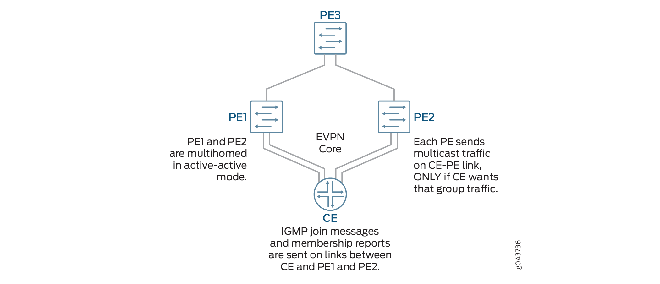
図1 は、2つのPEデバイス(PE1およびPE2)がカスタマーエッジ(CE)デバイスに接続されているEVPN-VXLAN環境を示しています。これらのPEは、冗長性を提供するために、アクティブ-アクティブモードでデュアルihome接続されます。3 番目の PE デバイスは、CE と対面する PE デバイスにトラフィックを転送します。IGMP は、IRB(統合型ルーティングおよびブリッジング)インターフェイスで有効です。CEデバイスは5つのVLANをホストします。IGMPスヌーピングは、すべてのVLANで有効になっています。この実装ではマルチキャスト ルーターの使用をサポートしていないため、PE 内の各 VLAN は IGMP レイヤー 2 クエリアとして有効になります。マルチホーム PE デバイスは、IGMP リスナーが存在するインターフェイスでのみ CE に向けてトラフィックを転送します。
設定
EVPN-VXLAN環境でIGMPスヌーピングを設定するには、以下のタスクを実行します。
CLIクイックコンフィグレーション
この例をすばやく設定するには、以下のコマンドをコピーしてテキストファイルに貼り付け、改行を削除し、ネットワーク設定に一致させる必要がある詳細情報を変更し、コマンドを [edit] 階層レベルでCLIにコピーアンドペーストして、設定モードから commit を入力します。
デバイスPE1
set chassis aggregated-devices ethernet device-count 2
set interfaces xe-0/0/0:1 description “Connected to CE”
set interfaces xe-0/0/0:2 ether-options 802.3ad ae1
set interfaces xe-0/0/1:0 enable
set interfaces xe-0/0/1:0 unit 0 description “Connected to PE3”
set interfaces xe-0/0/1:0 unit 0 family inet address 192.0.2.1/24
set interfaces ae0 enable
set interfaces ae1 enable
set interfaces lo0 unit 0 family inet address 192.168.1.1/32
set interfaces ae0 esi 00:11:11:11:11:11:11:11:11:11
set interfaces ae0 esi all-active
set interfaces ae0 aggregated-ether-options lacp active
set interfaces ae0 aggregated-ether-options lacp periodic fast
set interfaces ae0 aggregated-ether-options lacp system-id 00:00:00:00:00:01
set interfaces ae0 unit 0 description “Connected to CE”
set interfaces ae1 esi 00:22:22:22:22:22:22:22:22:22
set interfaces ae1 esi all-active
set interfaces ae1 aggregated-ether-options lacp active
set interfaces ae1 aggregated-ether-options periodic fast
set interfaces ae1 aggregated-ether-options lacp system id 00:00:00:00:00:02
set interfaces ae1 unit 0 description “Connected to CE”
set interfaces ae0 family ethernet-switching interface-mode trunk
set interfaces ae0 family ethernet-switching vlan members [ VLAN1 VLAN2 VLAN3 VLAN4 VLAN5 ]
set interfaces ae1 unit 0 family ethernet-switching interface-mode trunk
set interfaces ae1 unit 0 family ethernet-switching vlan [ VLAN1 VLAN2 VLAN3 VLAN4 VLAN5 ]
set interfaces irb unit 1 family inet address 10.1.1.1/24 virtual-gateway-address 10.1.1.10
set interfaces irb unit 2 family inet address 10.2.1.1/24 virtual-gateway-address 10.2.1.10
set interfaces irb unit 3 family inet address 10.3.1.1/24 virtual-gateway-address 10.3.1.10
set interfaces irb unit 4 family inet address 10.4.1.1/24 virtual-gateway-address 10.4.1.10
set interfaces irb unit 5 family inet address 10.5.1.1/24 virtual-gateway-address 10.5.1.10
set routing-options router-id 192.168.1.1
set routing-options autonomous-system 65536
set protocols ospf area 0.0.0.0 interface xe-0/0/1:0.0
set protocols ospf area 0.0.0.0 interface lo0.0 passive
set protocols bgp group INT type internal
set protocols bgp group INT local-address 192.168.1.1
set protocols bgp group INT family evpn signaling
set protocols bgp group INT local-as 65536
set protocols bgp group INT neighbor 172.16.1.1
set vlans VLAN vlan-id 1
set vlans VLAN1 l3-interface irb.1
set vlans VLAN1 vxlan vni 1
set vlans VLAN2 vlan-id 2
set vlans VLAN2 l3-interface irb.2
set vlans VLAN2 vxlan vni2
set vlans VLAN3 vlan-id 3
set vlans VLAN3 l3-interface irb.3
set vlans VLAN3 vxlan vni 3
set vlans VLAN4 vlan-id 4
set vlans VLAN4 l3-interface irb.4
set vlans VLAN4 vxlan vni 4
set vlans VLAN5 vlan-id 5
set vlans VLAN5 l3-interface irb.5
set vlans VLAN5 vxlan vni 5
set protocols evpn encapsulation vxlan
set protocols evpn ingress-replication
set protocols evpn extended-vni-list 1-5
set policy-options policy-statement evpn-pplb from protocol evpn
set policy-options policy-statement evpn-pplb then load-balance per-packet
set routing-options forwarding-table export evpn-pplb
set switch-options vtep-source-interface lo0:0
set switch-options route distinguisher 192.168.1.1:1
set switch-options vrf-target target:1:1
set protocols igmp interface irb.1
set protocols igmp interface irb.2
set protocols igmp interface irb.3
set protocols igmp interface irb.4
set protocols igmp interface irb.5
set protocols igmp-snooping vlan VLAN1 l2-querier source-address 10.1.1.1
set protocols igmp-snooping vlan VLAN1 proxy
set protocols igmp-snooping vlan VLAN2 l2-querier source-address 10.2.1.1
set protocols igmp-snooping vlan VLAN2 proxy
set protocols igmp-snooping vlan VLAN3 l2-querier source-address 10.3.1.1
set protocols igmp-snooping vlan VLAN3 proxy
set protocols igmp-snooping vlan VLAN4 l2-querier source-address 10.4.1.1
set protocols igmp-snooping vlan VLAN4 proxy
set protocols igmp-snooping vlan VLAN4 l2-querier source-address 10.5.1.1
set protocols igmp-snooping vlan VLAN5 proxy
set protocols pim rp static address 172.16.1.1
set protocols pim interface irb.1 distributed-dr
set protocols pim interface irb.2 distributed-dr
set protocols pim interface irb.3 distributed-dr
set protocols pim interface irb.4 distributed-dr
set protocols pim interface irb.5 distributed-dr
デバイスPE2
set chassis aggregated-devices ethernet device-count 2
set interfaces xe-0/0/0:0 ether-options 802.3ad ae1
set interfaces xe-0/0/0:1 description “Connected to CE”
set interfaces xe-0/0/0:1 ether-options 802.3ad ae0
set interfaces xe-0/0/1:0 enable
set interfaces xe-0/0/1:0 unit 0 description “Connected to PE3”
set interfaces xe-0/0/1:0 family inet address 198.51.100.1/24
set interfaces ae0 enable
set interfaces ae1 enable
set interfaces lo0 unit 0 family inet address 192.168.2.1/32
set interfaces ae0 esi 00:11:11:11:11:11:11:11:11:11
set interfaces ae0 esi all-active
set interfaces ae0 aggregated-ether-options lacp active
set interfaces ae0 aggregated ether-options lacp periodic fast
set interfaces ae0 aggregated ether-options lacp system-id 00:00:00:00:00:01
set interfaces ae1 esi 00:22:22:22:22:22:22:22:22:22
set interfaces ae1 esi all-active
set interfaces ae1 aggregated-ether-options lacp active
set interfaces ae1 aggregated-ether-options lacp periodic fast
set interfaces ae1 aggregated-ether-options lacp system-id 00:00:00:00:00:02
set interfaces ae0 unit 0 description “Connected to CE”
set interfaces ae0 unit family ethernet-switching interface-mode trunk
set interfaces ae0 unit family ethernet-switching vlan members [ VLAN1 VLAN2 VLAN3 VLAN4 VLAN5 ]
set interfaces ae1 unit 0 description “Connected to CE”
set interfaces ae1 unit 0 family ethernet-switching interface-mode trunk
set interfaces ae1 unit 0 family ethernet-switching vlan members [ VLAN1 VLAN2 VLAN3 VLAN4 VLAN5 ]
set interfaces irb unit 1 family inet address 10.1.1.2/24 virtual-gateway-address 10.1.1.10
set interfaces irb unit 2 family inet address 10.2.1.2/24 virtual-gateway-address 10.2.1.10
set interfaces irb unit 3 family inet address 10.3.1.2/24 virtual-gateway-address 10.3.1.10
set interfaces irb unit 4 family inet address 10.4.1.2/24 virtual-gateway-address 10.4.1.10
set interfaces irb unit 5 family inet address 10.5.1.2/24 virtual-gateway-address 10.5.1.10
set routing-options router-id 192.168.2.1
set routing-options autonomous-system 65536
set protocols ospf area 0.0.0.0 interface lo0.0 passive
set protocols ospf area 0.0.0.0 interface xe-0/0/1:0.0
set protocols bgp group INT type internal
set protocols bgp group INT local-address 192.168.2.1
set protocols bgp group INT family evpn signaling
set protocols bgp group INT local-as 65536
set protocols bgp group INT neighbor 172.16.1.1
set vlans VLAN1 vlan-id 1
set vlans VLAN1 l3-interface irb.1
set vlans VLAN1 vxlan vni 1
set vlans VLAN2 vlan-id 2
set vlans VLAN2 l3-interface irb.2
set vlans VLAN2 vxlan vni 2
set vlans VLAN3 vlan-id 3
set vlans VLAN3 l3-interface irb.3
set vlans VLAN3 vxlan vni 3
set vlans VLAN4 vlan-id 4
set vlans VLAN4 l3-interface irb.4
set vlans VLAN4 vxlan vni 4
set vlans VLAN5 vlan-id 5
set vlans VLAN5 l3-interface irb.5
set vlans VLAN5 vxlan vni 3
set protocols evpn encapsulation vxlan
set protocols evpn muticast-mode ingress-encapsulation
set protocols evpn extended-vni-list 1-5
set policy-options policy statement evpn-pplb from protocol evpn
set policy-options policy-statement evpn-pplb then load-balance per-packet
set routing-options forwarding-table export evpn-pplb
set switch-options vtep-source-interface lo0.0
set switch-options route-distinguisher 192.168.2.1:1
set switch-options vrf-target target:1:1
set protocols igmp interface irb.1
set protocols igmp interface irb.2
set protocols igmp interface irb.3
set protocols igmp interface irb.4
set protocols igmp interface irb.5
set protocols igmp-snooping vlan VLAN1 l2-querier source-address 10.1.1.2
set protocols igmp-snooping vlan VLAN1 proxy
set protocols igmp-snooping vlan VLAN2 l2-querier source-address 10.2.1.2
set protocols igmp-snooping vlan VLAN2 proxy
set protocols igmp-snooping vlan VLAN3 l2-querier source-address 10.3.1.2
set protocols igmp-snooping vlan VLAN3 proxy
set protocols igmp-snooping vlan VLAN4 l2-querier source-address 10.4.1.2
set protocols igmp-snooping vlan VLAN4 proxy
set protocols igmp-snooping vlan VLAN5 l2-querier source-address 10.5.1.2
set protocols igmp-snooping vlan VLAN5 proxy
set protocols pim rp static address 172.16.1.1
set protocols pim interface irb.1 distributed-dr
set protocols pim interface irb.2 distributed-dr
set protocols pim interface irb.3 distributed-dr
set protocols pim interface irb.4 distributed-dr
set protocols pim interface irb.5 distributed-dr
CE
set chassis aggregated devices ethernet device-count 2
set interfaces xe-0/2/0 ether-options 802.3ad ae0
set interfaces xe-0/2/1 ether-options 802.3ad ae0
set interfaces xe-0/2/0 unit 0 family ethernet-switching interface-mode trunk
set interfaces xe-0/2/0 unit 0 family ethernet-switching vlan members 1-5
set interfaces xe-0/2/1 unit 0 family ethernet-switching interface-mode trunk
set interfaces xe-0/2/1 unit 0 family ethernet-switching vlan members 1-5
set interfaces ae0 aggregated-ether-options lacp active
set interfaces ae0 aggregated-ether-options lacp periodic fast
set interfaces ae0 unit 0 family ethernet-switching interface-mode trunk
set interfaces ae0 unit 0 family ethernet-switching vlan members 1-5
set interfaces ae1 aggregated-ether-options lacp active
set interfaces ae1 aggregated-ether-options lacp periodic fast
set interfaces ae1 unit 0 family ethernet-switching interface-mode trunk
set interfaces ae1 unit 0 family ethernet-switching vlan members 1-5
set vlans BD-1 vlan-id 1
set vlans BD-2 vlan-id 2
set vlans BD-3 vlan-id 3
set vlans BD-4 vlan-id 4
set vlans BD-5 vlan-id 5
PE3
set interfaces xe-0/0/0 enable
set interfaces xe-/0/0/0 unit 0 description “Connected to PE1”
set interfaces xe-0/0/0 unit 0 family inet 192.0.2.2/24
set interfaces xe-0/0/1 enable
set interfaces xe-0/0/1 unit 0 description “Connected to PE2”
set interfaces xe-0/0/1 unit 0 family inet 198.51.100.2/24
set interfaces lo0 unit 0 family inet address 172.16.1.1/32
set interfaces xe-0/0/0:1 enable
set interfaces xe-0/0/0:1 unit 0 family ethernet-switching interface-mode trunk
set interfaces xe-0/0/0:1 unit 0 family ethernet-switching vlan members [ VLAN1 VLAN2 VLAN3 VLAN4 VLAN5 ]
set interfaces xe-0/0/1:1 enable
set interfaces xe-0/0/1:1 unit 0 family ethernet-switching interface-mode trunk
set interfaces xe-0/0/1:1 unit 0 family ethernet-switching vlan members [ VLAN1 VLAN2 VLAN3 VLAN4 VLAN5 ]
set interfaces irb unit 1 famly inet address 10.1.1.5/24 virtual-gateway address 10.1.1.10
set interfaces irb unit 2 family inet address 10.2.1.5/24 virtual-gateway address 10.2.1.10
set interfaces irb unit 3 family inet address 10.3.1.5/24 virtual-gateway address 10.3.1.10
set interfaces irb unit 4 family inet address 10.4.1.5/24 virtual-gateway address 10.4.1.10
set interrfaces irb unit 5 family inet address 10.5.1.5/24 virtual-gateway address 10.5.1.10
set routing-options router-id  172.16.1.1
se routing-options autonomous-system 65536
set ospf area 0.0.0.0 interface all
set ospf area 0.0.0.0 fxp0.0 disable
set protocols bgp group INT type internal
set protocols bgp group INT  local-address 172.16.1.1
set protocols bgp group INT family evpn signaling
set protocols bgp group INT local-as 65536
set protocols bgp group INT neighbor 192.168.1.1
set protocols bgp group INT neighbor 192.168.2.1
set vlans VLAN1 vlan-id 1
set vlans VLAN1 l3-interface irb.1
set vlans VLAN1 vxlan vni 1
set vlans VLAN2 vlan-id 2
set vlans VLAN2 l3-interface irb.2
set vlans VLAN2 vxlan vni 2
set vlans VLAN3 vlan-id 3
set vlans VLAN3 l3-interface irb.3
set vlans VLAN3 vxlan vni 3
set vlans VLAN4 vlan-id 4
set vlans VLAN4 l3-interface irb.4
set vlans VLAN4 vxlan vni 4
set vlans VLAN5 vlan-id 5
set vlans VLAN5 l3-interface irb.5
set vlans VLAN5 vxlan vni 5
set protocols evpn encapsulation vxlan
set protocols evpn multicast-mode ingress-replication
set protocols evpn extended-vni-list 1-5
set policy-options policy-statement evpn-pplb from protocol evpn
set policy-options policy-statement evpn-pbllb then load-balance per packet
set routing-options forwarding-table export evpn-pplb
set switch-options vtep-source-interface lo0
set switch-options route-distinguisher 172.16.1.1:1
set switch-option vrf-target target:1:1
set protocols igmp interface irb.1
set protocols igmp interface irb.2
set protocols igmp interface irb.3
set protocols igmp interface irb.4
set protocols igmp interface irb.5
set protocols igmp-snooping vlan VLAN1 l2-querier source-address 10.1.1.5
set protocols igmp-snooping vlan VLAN1 proxy
set protocols igmp-snooping vlan VLAN2 l2-querier source-address 10.2.1.5
set protocols igmp-snooping vlan VLAN2 proxy
set protocols igmp-snooping vlan VLAN3 l2-querier source-address 10.3.1.5
set protocols igmp-snooping vlan VLAN3 proxy
set protocols igmp-snooping vlan VLAN4 l2-querier source-address 10.4.1.5
set protocols igmp-snooping vlan VLAN4 proxy
set protocols igmp-snooping vlan VLAN5 l2-querier source-address 10.5.1.5
set protocols igmp-snooping vlan VLAN5 proxy
set protocols pim rp local 172.16.1.1
set protocols pim interface irb.1 distributed-dr
set protocols pim interface irb.2 distributed-dr
set protocols pim interface irb.3 distributed-dr
set protocols pim interface irb.4 distributed-dr
set protocols pim interface irb.5 distributed-dr
PE1の設定
ステップバイステップの手順
次の例では、設定階層のさまざまなレベルに移動する必要があります。CLIのナビゲーションについては、『CLIユーザーガイド』の「設定モードでのCLIエディターの使用」を参照してください。
デバイスPE1を設定するには:
-
集合型イーサネット論理インターフェイスの数を指定します。
[edit chassis] user@PE1# set aggregated-devices ethernet device-count 2 -
インターフェイスを設定します。
[edit interfaces]
user@PE1# set xe-0/0/0:1 description “Connected to CE”
user@PE1# set xe-0/0/0:2 ether-options 802.3ad ae1
user@PE1# set xe-0/0/1:0 enable
user@PE1# set xe-0/0/1:0 unit 0 description “Connected to PE3”
user@PE1# set xe-0/0/1:0 unit 0 family inet address 192.0.2.1/24
user@PE1# set ae0 enable
user@PE1# set ae1 enable
user@PE2# set lo0 unit 0 family inet address 192.168.1.1/32
-
各集合型イーサネットインターフェイスでアクティブ-アクティブマルチホーミングを設定し、LACP(Link Aggregation Control Protocol)を有効にします。
[edit interfaces]
user@PE1# set ae0 esi 00:11:11:11:11:11:11:11:11:11
user@PE1# set esi all-active
user@PE1# set ae0 aggregated-ether-options lacp active
user@PE1# set ae0 aggregated-ether-options lacp periodic-fast
user@PE1# set ae0 aggregated-ether-options lacp system-id 00:00:00:00:00:01
user@PE1# set ae1 esi 00:22:22:22:22:22:22:22:22:22
user@PE1# set ae1 esi all-active
user@PE1# set ae1 aggregated-ether-options lacp active
user@PE1# set ae1 aggregated-ether-options lacp periodic-fast
user@PE1# set ae0 aggregated-ether-options lacp system-id 00:00:00:00:00:02
-
集約された各イーサネットインターフェイスをトランクポートとして設定します。
[edit interfaces]
user@PE1# set ae0 unit 0 description “Connected to CE”
user@PE1# set ae0 unit 0 family ethernet-switching interface-mode trunk
user@PE1# set ae0 unit 0 family ethernet-switching vlan members [ VLAN1 VLAN2 VLAN3 VLAN4 VLAN5 ]
user@PE1# set ae1 unit 0 description “Connected to CE”
user@PE1# set ae1 unit 0 family ethernet-switching interface-mode trunk
user@PE1# set ae1 unit 0 family ethernet-switching vlan members [ VLAN1 VLAN2 VLAN3 VLAN4 VLAN5 ]
-
IRB インターフェイスと仮想ゲートウェイ アドレスを設定します。
[edit interfaces]
user@PE1# set irb unit 1 family inet address 10.1.1.1/24 virtual-gateway-address 10.1.1.10
user@PE1# set irb unit 2 family inet address 10.2.1.1/24 virtual-gateway-address 10.2.1.10
user@PE1# set irb unit 3 family inet address 10.3.1.1/24 virtual-gateway-address 10.3.1.10
user@PE1# set irb unit 4 family inet address 10.4.1.1/24 virtual-gateway-address 10.4.1.10
user@PE1# set irb unit 5 family inet address 10.5.1.1/24 virtual-gateway-address 10.5.1.10
-
自律システムを設定します。
[edit routing-options]
user@PE1# set router-id 192.168.1.1
user@PE1# set autonomous-system 65536
-
OSPFを設定します。
[edit protocols ospf]
user@PE1# set area 0.0.0.0 interface xe-0/0/1:0.0
user@PE1# set area 0.0.0.0 interface lo0. passive
-
BGP内部ピアリングを設定します。
[edit protocols bgp]
user@PE1# set group INT type internal
user@PE1# set group INT local-address 192.168.1.1
user@PE1# set group INT family evpn signaling
user@PE1# set group INT local-as 65536
user@PE1# set group INT neighbor 172.16.1.1
-
VLANを設定します。
[set vlans]
user@PE1# set VLAN1 vlan-id 1
user@PE1# set VLAN1 l3-interface irb.1
user@PE1# set VLAN1 vxlan vni 1
user@PE1# set VLAN2 vlan-id 2
user@PE1# set VLAN2 l3-interface irb.2
user@PE1# set VLAN2 vxlan vni 2
user@PE1# set VLAN3 vlan-id 3
user@PE1# set VLAN3 l3-interface irb.3
user@PE1# set VLAN3 vxlan vni 3
user@PE1# set VLAN4 vlan-id 4
user@PE1# set VLAN4 l3-interface irb.4
user@PE1# set VLAN4 vxlan vni 4
user@PE1# set VLAN5 vlan-id 5
user@PE1# set VLAN5 l3-interface irb.5
user@PE1# set VLAN2 vxlan vni 5
-
EVPNを有効にします。
[edit protocols evpn]
user@PE1# set encapsulation vxlan
user@PE1# set multicast-mode ingress-replication
user@PE1# set extended-vni-list 1-5
-
エクスポートルーティングポリシーを設定して、EVPNトラフィックの負荷を分散します。
[edit policy-options]
user@PE1# set policy-statement evpn-pplb from protocol evpn
user@PE1# set policy-statement evpn-pplb then load-balance per packet

[edit routing-options]
user@PE1# set forwarding-table export evpn-pplb
-
VXLAN トンネルの送信元インターフェイスを設定します。
[edit switch-options]
user@PE1# set vtep-source-interface lo0.0
user@PE1# set route-distinguisher 192.168.1.1:1
user@PE1# set vrf-target target:1:1
-
VLAN に関連付けられた IRB インターフェイスで IGMP を有効にします。
[edit protocols igmp]
user@PE1# set interface irb.1
user@PE1# set interface irb.2
user@PE1# set interface irb.3
user@PE1# set interface irb.4
user@PE1# set interface irb.5
-
VLAN で IGMP スヌーピングを有効にします。
[edit protocols igmp-snooping vlan]
user@PE1# set VLAN1 l2-querier source-address 10.1.1.1
user@PE1# set VLAN1 proxy
user@PE1# set VLAN2 l2-querier source-address 10.2.1.1
user@PE1# set VLAN2 proxy
user@PE1# set VLAN3 l2-querier source address 10.3.1.1
user@PE1# set VLAN3 proxy
user@PE1# set VLAN4 l2-querier source-address 10.4.1.1
user@PE1# set VLAN4 proxy
user@PE1# set VLAN5 l2-querier source-address 10.5.1.1
user@PE1# set VLAN5 proxy
-
静的なランデブー ポイントを定義し、VLAN に関連付けられた IRB インターフェイスで有効にして PIM を設定します。
注:この手順は、VLAN 間転送を設定する場合にのみ必要です。PEデバイスがVLAN内転送のみを実行している場合は、このステップを省略します。
[edit protocols pim]
user@PE1# set rp static address 172.16.1.1
user@PE1# set interface irb.1 distrbuted-dr
user@PE1# set interface irb.2 distributed-dr
user@PE1# set interface irb.3 distributed-dr
user@PE1# set interface irb.4 distributed-dr
user@PE1# set interface irb.5 distributed-dr
結果
設定モードから、 show chassis、 show interfaces、 show routing-options、show protocols、 show vlans、 show policy-options、 show switch-options コマンドを入力して設定を確認します。出力に意図した設定が表示されない場合は、この例の手順を繰り返して設定を修正します。
user@PE1# show chassis
aggregated-devices {
    ethernet {
        device-count 2;
    }
}
user@PE1# show
interfaces {
    xe-0/0/0:1 {
        description "Connected to CE";
        ether-options {
            802.3ad ae0;
        }
    }
    xe-0/0/0:2 {
        ether-options {
            802.3ad ae1;
        }
    }
    xe-0/0/1:0 {
        enable;
        unit 0 {
            description "Connected to PE3";
            family inet {
                address 192.0.2.1/24;
            }
        }
    }
    xe-0/0/1:1 {
        enable;
    }
    ae0 {
        enable;
        esi {
            00:11:11:11:11:11:11:11:11:11;
            all-active;
        }
        aggregated-ether-options {
            lacp {
                active;
                periodic fast;
                system-id 00:00:00:00:00:01;
            }
        }
        unit 0 {
            description "Connected to CE";
            family ethernet-switching {
                interface-mode trunk;
                vlan {
                    members [ VLAN1 VLAN2 VLAN3 VLAN4 VLAN5 ];
                }
            }
        }
    }
    ae1 {
        enable;
        esi {
            00:22:22:22:22:22:22:22:22:22;
            all-active;
        }
        aggregated-ether-options {
            lacp {
                active;
                periodic fast;
                system-id 00:00:00:00:00:02;
            }
        }
        unit 0 {
            description "Connected to CE";
            family ethernet-switching {
                interface-mode trunk;
                vlan {
                    members [ VLAN1 VLAN2 VLAN3 VLAN4 VLAN5 ];
                }
            }
        }
    }
    irb {
        unit 1 {
            family inet {
                address 10.1.1.1/24 {
                    virtual-gateway-address 10.1.1.10;
                }
            }
        }
        unit 2 {
            family inet {
                address 10.2.1.1./24 {
                    virtual-gateway-address 10.2.1.10;
                }
            }
        }
        unit 3 {
            family inet {
                address 10.3.1.1./24 {
                    virtual-gateway-address 10.3.1.10;
                }
            }
        }
        unit 4 {
            family inet {
                address 10.4.1.1./24 {
                    virtual-gateway-address 10.4.1.10;
                }
            }
        }
        unit 5 {
            family inet {
                address 10.5.1.1./24 {
                    virtual-gateway-address 10.5.1.10;
                }
            }
        }
    }
    lo0 {
        unit 0 {
            family inet {
                address 192.168.1.1/32;
            }
        }
    }
}
routing-options {
    router-id  192.168.1.1;
    autonomous-system 65536;
    forwarding-table {
        export evpn-pplb;
    }
}
protocols {
    igmp {
        interface irb.1;
        interface irb.2;
        interface irb.3;
        interface irb.4;
        interface irb.5;
    }
    bgp {
        group INT {
            type internal;
            local-address 192.168.1.1;
            family evpn {
                signaling;
            }
            local-as 65536;
            neighbor 172.16.1.1;
        }
    }
    ospf {
        area 0.0.0.0 {
            interface xe-0/0/1:0.0;
            interface lo0.0 {
                passive;
            }
        }
    }
    pim {
        rp {
            static {
                address 172.16.1.1;
            }
        }
        interface irb.1 {
            distributed-dr;
        }
        interface irb.2 {
            distributed-dr;
        }
        interface irb.3 {
            distributed-dr;
        }
        interface irb.4 {
            distributed-dr;
        }
        interface irb.5 {
            distributed-dr;
        }
    }
    evpn {
        encapsulation vxlan;
        multicast-mode ingress-replication;
        extended-vni-list 1-5;
    }
    igmp-snooping {
        vlan VLAN1 {
            l2-querier {
                source-address 10.1.1.1;
            }
            proxy;
        }
        vlan VLAN2 {
            l2-querier {
                source-address 10.2.1.1;
            }
            proxy;
        }
        vlan VLAN3 {
            l2-querier {
                source-address 10.3.1.1;
            }
            proxy;
        }
        vlan VLAN4 {
            l2-querier {
                source-address 10.4.1.1;
            }
            proxy;
        }
        vlan VLAN5 {
            l2-querier {
                source-address 10.5.1.1;
            }
            proxy;
        }
    }
}
policy-options {
    policy-statement evpn-pplb {
        from protocol evpn;
        then {
            load-balance per-packet;
        }
    }
}
switch-options {
    vtep-source-interface lo0.0;
    route-distinguisher 192.168.1.1:1;
    vrf-target target:1:1;
}
vlans {
    VLAN1 {
        vlan-id 1;
        l3-interface irb.1;
        vxlan {
            vni 1;
        }
    }
    VLAN2 {
        vlan-id 2;
        l3-interface irb.2;
        vxlan {
            vni 2;
        }
    }
    VLAN3 {
        vlan-id 3;
        l3-interface irb.3;
        vxlan {
            vni 3;
        }
    }
    VLAN4 {
        vlan-id 4;
        l3-interface irb.4;
        vxlan {
            vni 4;
        }
    }
    VLAN5 {
        vlan-id 5;
        l3-interface irb.5;
        vxlan {
            vni 5;
        }
    }
}
PE2の設定
ステップバイステップの手順
次の例では、設定階層のさまざまなレベルに移動する必要があります。CLIのナビゲーションについては、『CLIユーザーガイド』の「設定モードでのCLIエディターの使用」を参照してください。
デバイスPE2を設定するには:
-
集合型イーサネット論理インターフェイスの数を指定します。
[edit chassis]
user@PE2# set aggregated-devices ethernet device-count 2
-
インターフェイスを設定します。
[edit interfaces]
user@PE2# set xe-0/0/0:0 ether-options 802.3ad ae1
user@PE2# set xe-0/0/0:1 description “Connected to CE”
user@PE2# set xe-0/0/1:0 enable
user@PE2# set xe-0/0/1:0 unit 0 description “Connected to PE3”
user@PE2# set xe-0/0/1:0 unit 0 family inet address 198.51.100.1/24
user@PE2# set ae0 enable
user@PE2# set ae1 enable
user@PE2# set lo0 unit 0 family inet address 192.168.2.1/32
-
各集合型イーサネットインターフェイスでアクティブ-アクティブマルチホーミングを設定し、LACP(Link Aggregation Control Protocol)を有効にします。
[edit interfaces]
user@PE2# set ae0 esi 00:11:11:11:11:11:11:11:11:11
user@PE2# set esi all-active
user@PE2# set ae0 aggregated-ether-options lacp active
user@PE2# set ae0 aggregated-ether-options lacp periodic-fast
user@PE2# set ae0 aggregated-ether-options lacp system-id 00:00:00:00:00:01
user@PE2# set ae1 esi 00:22:22:22:22:22:22:22:22:22
user@PE2# set ae1 esi all-active
user@PE2# set ae1 aggregated-ether-options lacp active
user@PE2# set ae1 aggregated-ether-options lacp periodic-fast
user@PE2# set ae0 aggregated-ether-options lacp system-id 00:00:00:00:00:02
-
集約された各イーサネットインターフェイスをトランクポートとして設定します。
[edit interfaces]
user@PE2# set ae0 unit 0 description “Connected to CE”
user@PE2# set ae0 unit 0 family ethernet-switching interface-mode trunk
user@PE2# set ae0 unit 0 family ethernet-switching vlan members [ VLAN1 VLAN2 VLAN3 VLAN4 VLAN5 ]
user@PE2# set ae1 unit 0 description “Connected to CE”
user@PE2# set ae1 unit 0 family ethernet-switching interface-mode trunk
user@PE2# set ae1 unit 0 family ethernet-switching vlan members [ VLAN1 VLAN2 VLAN3 VLAN4 VLAN5 ]
-
IRB インターフェイスと仮想ゲートウェイ アドレスを設定します。
[edit interfaces]
user@PE2# set irb unit 1 family inet address 10.1.1.2/24 virtual-gateway-address 10.1.1.10
user@PE2# set irb unit 2 family inet address 10.2.1.2/24 virtual-gateway-address 10.2.1.10
user@PE2# set irb unit 3 family inet address 10.3.1.2/24 virtual-gateway-address 10.3.1.10
user@PE2# set irb unit 4 family inet address 10.4.1.2/24 virtual-gateway-address 10.4.1.10
user@PE2# set irb unit 5 family inet address 10.5.1.2/24 virtual-gateway-address 10.5.1.10
-
自律システムを設定します。
[edit routing-options]
user@PE2# set router-id 192.168.2.1
user@PE2# set autonomous-system 65536
-
OSPFを設定します。
[edit protocols ospf]
user@PE2# set area 0.0.0.0 interface xe-0/0/1:0.0
user@PE2# set area 0.0.0.0 interface lo0. passive
-
BGP内部ピアリングを設定します。
[edit protocols bgp]
user@PE2# set group INT type internal
user@PE2# set group INT local-address 192.168.2.1
user@PE2# set group INT family evpn signaling
user@PE2# set group INT local-as 65536
user@PE2# set group INT neighbor 172.16.1.1
-
VLANを設定します。
[edit vlans]
user@PE2# set VLAN1 vlan-id 1
user@PE2# set VLAN1 l3-interface irb.1
user@PE2# set VLAN1 vxlan vni 1
user@PE2# set VLAN2 vlan-id 2
user@PE2# set VLAN2 l3-interface irb.2
user@PE2# set VLAN2 vxlan vni 2
user@PE2# set VLAN3 vlan-id 3
user@PE2# set VLAN3 l3-interface irb.3
user@PE2# set VLAN3 vxlan vni 3
user@PE2# set VLAN4 vlan-id 4
user@PE2# set VLAN4 l3-interface irb.4
user@PE2# set VLAN4 vxlan vni 4
user@PE2# set VLAN5 vlan-id 5
user@PE2# set VLAN5 l3-interface irb.5
user@PE2# set VLAN2 vxlan vni 5
-
EVPNを有効にします。
[edit protocols evpn]
user@PE2# set encapsulation vxlan
user@PE2# set multicast-mode ingress-replication
user@PE2# set extended-vni-list 1-5
-
エクスポートルーティングポリシーを設定して、EVPNトラフィックをロードバランシングし、転送テーブルに適用します。
[edit policy-options]
user@PE2# set policy-statement evpn-pplb from protocol evpn
user@PE2# set policy-statement evpn-pplb then load-balance per packet

[edit routing-options]
user@PE2# set forwarding-table export evpn-pplb
-
VXLAN トンネルの送信元インターフェイスを設定します。
[edit switch-options]
user@PE2# set vtep-source-interface lo0.0
user@PE2# set route-distinguisher 192.168.2.1:1
user@PE2# set vrf-target target:1:1
-
IRB インターフェイスで IGMP を有効にします。
[edit protocols igmp]
user@PE2# set interface irb.1
user@PE2# set interface irb.2
user@PE2# set interface irb.3
user@PE2# set interface irb.4
user@PE2# set interface irb.5
-
IRB インターフェイスで IGMP スヌーピングを有効にします。
[edit protocols igmp-snooping vlan]
user@PE2# set VLAN1 l2-querier source-address 10.1.1.2
user@PE2# set VLAN1 proxy
user@PE2# set VLAN2 l2-querier source-address 10.2.1.2
user@PE2# set VLAN2 proxy
user@PE2# set VLAN3 l2-querier source address 10.3.1.2
user@PE2# set VLAN3 proxy
user@PE2# set VLAN4 l2-querier source-address 10.4.1.2
user@PE2# set VLAN4 proxy
user@PE2# set VLAN5 l2-querier source-address 10.5.1.2
user@PE2# set VLAN5 proxy
-
静的なランデブー ポイントを定義し、IRB インターフェイスで有効にすることで PIM を設定します。
注:この手順は、VLAN 間転送を設定する場合にのみ必要です。PEデバイスがVLAN内転送のみを実行している場合は、このステップを省略します。
[edit protocols pim]
user@PE2# set rp static address 172.16.1.1
user@PE2# set interface irb.1 distrbuted-dr
user@PE2# set interface irb.2 distributed-dr
user@PE2# set interface irb.3 distributed-dr
user@PE2# set interface irb.4 distributed-dr
user@PE2# set interface irb.5 distributed-dr
結果
設定モードから、 show chassis、 show interfaces、 show routing-options、show protocols、 show vlans、 show policy-options、 show switch-options コマンドを入力して設定を確認します。出力に意図した設定が表示されない場合は、この例の手順を繰り返して設定を修正します。
user@PE2# show chassis
aggregated-devices {
    ethernet {
        device-count 2;
    }
}
user@PE2# show
interfaces {
    xe-0/0/0:0 {
        ether-options {
            802.3ad ae1;
        }
    }
    xe-0/0/0:1 {
        description "Connected to CE";
        ether-options {
            802.3ad ae0;
        }
    }
    xe-0/0/1:0 {
        enable;
        unit 0 {
            description "Connected to PE3";
            family inet {
                address 198.51.100.1/24;
            }
        }
    }
    ae0 {
        esi {
            00:11:11:11:11:11:11:11:11:11;
            all-active;
        }
        aggregated-ether-options {
            lacp {
                active;
                periodic fast;
                system-id 00:00:00:00:00:01;
            }
        }
        unit 0 {
            description "Connected to CE";
            family ethernet-switching {
                interface-mode trunk;
                vlan {
                    members [ VLAN1 VLAN2 VLAN3 VLAN4 VLAN5 ];
                }
            }
        }
    }
    ae1 {
        enable;
        esi {
            00:22:22:22:22:22:22:22:22:22;
            all-active;
        }
        aggregated-ether-options {
            lacp {
                active;
                periodic fast;
                system-id 00:00:00:00:00:02;
            }
        }
        unit 0 {
            description "CONNECTED TO CE";
            family ethernet-switching {
                interface-mode trunk;
                vlan {
                    members [ VLAN1 VLAN2 VLAN3 VLAN4 VLAN5 ];
                }
            }
        }
    }
    irb {
        unit 1 {
            family inet {
                address 10.1.1.2/24 {
                    virtual-gateway-address 10.1.1.10;
                }
            }
        }
        unit 2 {
            family inet {
                address 10.2.1.2/24 {
                    virtual-gateway-address 10.2.1.10;
                }
            }
        }
        unit 3 {
            family inet {
                address 10.3.1.2/24 {
                    virtual-gateway-address 10.3.1.10;
                }
            }
        }
        unit 4 {
            family inet {
                address 10.4.1.2/24 {
                    virtual-gateway-address 10.4.1.10;
                }
            }
        }
        unit 5 {
            family inet {
                address 10.5.1.2/24 {
                    virtual-gateway-address 10.5.1.10;
                }
            }
        }
    }
    lo0 {
        unit 0 {
            family inet {
                address 192.168.2.1/32;
            }
        }
    }
}
routing-options {
    router-id 192.168.2.1;
    autonomous-system 65536;
    forwarding-table {
        export evpn-pplb;
    }
}
protocols {
    igmp {
        interface irb.1;
        interface irb.2;
        interface irb.3;
        interface irb.4;
        interface irb.5;
    }
    bgp {
        group INT {
            type internal;
            local-address 192.168.2.1;
            family evpn {
                signaling;
            }
            local-as 65536;
            neighbor 172.16.1.1;
        }
    }
    ospf {
        area 0.0.0.0 {
            interface lo0.0 {
                passive;
            }
            interface xe-0/0/1:0.0;
        }
    }
    pim {
        rp {
            static {
                address 172.16.1.1;
            }
        }
        interface irb.1 {
            distributed-dr;
        }
        interface irb.2 {
            distributed-dr;
        }
        interface irb.3 {
            distributed-dr;
        }
        interface irb.4 {
            distributed-dr;
        }
        interface irb.5 {
            distributed-dr;
        }
    }
    evpn {
        encapsulation vxlan;
        multicast-mode ingress-replication;
        extended-vni-list 1-5;
    }
    igmp-snooping {
        vlan VLAN1 {
            l2-querier {
                source-address 10.1.1.2;
            }
            proxy;
        }
        vlan VLAN2 {
            l2-querier {
                source-address 10.2.1.2;
            }
            proxy;
        }
        vlan VLAN3 {
            l2-querier {
                source-address 10.3.1.2;
            }
            proxy;
        }
        vlan VLAN4 {
            l2-querier {
                source-address 10.4.1.2;
            }
            proxy;
        }
        vlan VLAN5 {
            l2-querier {
                source-address 10.5.1.2;
            }
            proxy;
        }
    }
}
policy-options {
    policy-statement evpn-pplb {
        from protocol evpn;
        then {
            load-balance per-packet;
        }
    }
}
switch-options {
    vtep-source-interface lo0.0;
    route-distinguisher 192.168.2.1:1;
    vrf-target target:1:1;
}
vlans {
    VLAN1 {
        vlan-id 2;
        l3-interface irb.2;
        vxlan {
            vni 2;
        }
    }
    VLAN2 {
        vlan-id 1;
        l3-interface irb.1;
        vxlan {
            vni 1;
        }
    }
    VLAN3 {
        vlan-id 3;
        l3-interface irb.3;
        vxlan {
            vni 3;
        }
    }
    VLAN4 {
        vlan-id 4;
        l3-interface irb.4;
        vxlan {
            vni 4;
        }
    }
    VLAN5 {
        vlan-id 5;
        l3-interface irb.5;
        vxlan {
            vni 5;
        }
    }
}
CEデバイスの設定
ステップバイステップの手順
次の例では、設定階層のさまざまなレベルに移動する必要があります。CLIのナビゲーションについては、『CLIユーザーガイド』の「設定モードでのCLIエディターの使用」を参照してください。
デバイスCEを設定するには:
-
集合型イーサネット論理インターフェイスの数を指定します。
[edit chassis]
user@CE# set aggregated-devices ethernet device-count 2
-
インターフェイスを設定し、集合型イーサネットインターフェイスでLACPを有効にします。
[edit interfaces]
user@CE# set xe-0/2/0 ether-options 802.3ad ae0
user@CE# set xe-0/2/1 ether-options 802.3ad ae0
user@CE# set ae0 aggregated ether-options lacp active
user@CE# set ae0 aggregated ether-options lacp periodic fast
user@CE# set ae1 aggregated ether-options lacp active
user@CE# set ae1 aggregated ether-options lacp periodic fast
-
レイヤー 2 カスタマー ブリッジ ドメインと、ドメインに関連付けられた VLAN を作成します。
[edit]
user@CE# set vlans BD-1 vlan-id 1
user@CE# set vlans BD-2 vlan-id 2
user@CE# set vlans BD-3 vlan-id 3
user@CE# set vlans BD-4 vlan-id 4
user@CE# set vlans BD-5 vlan-id 5
-
各インターフェイスを、指定されたVLAN識別子でタグ付きパケットを受け入れるためのトランクポートとしてCEドメインに含めるように設定します。
[edit interfaces]
user@CE# set xe-0/2/0 unit 0 family ethernet-switching interface-mode trunk
user@CE# set xe-0/2/0 unit 0 family ethernet-switching vlan members 1-5
user@CE# set xe-0/2/1 unit 0 family ethernet-switching interface-mode trunk
user@CE# set xe-0/2/1 unit 0 family ethernet-switching vlan members 1-5
user@CE# set ae0 unit 0 family ethernet-switching interface-mode trunk
user@CE# set ae0 unit 0 family ethernet-switching vlan members 1-5
user@CE# set ae1 unit 0 family ethernet-switching interface-mode trunk
user@CE# set ae1 unit 0 family ethernet-switching vlan members 1-5
結果
設定モードから、 show chassis および show interfaces コマンドを入力して設定を確認します。出力に意図した設定が表示されない場合は、この例の手順を繰り返して設定を修正します。
user@CE# show chassis
aggregated-devices {
    ethernet {
        device-count 2;
    }
}
user@CE# show interfaces
xe-0/2/0 {
    ether-options {
        802.3ad ae0;
    }
    unit 0 {
        family ethernet-switching {
            interface-mode trunk;
            vlan {
                members 1-5;
            }
        }
    }
}
xe-0/2/1 {
    ether-options {
        802.3ad ae0;
    }
    unit 0 {
        family ethernet-switching {
            interface-mode trunk;
            vlan {
                members 1-5;
            }
        }
    }
}
ae0 {
    aggregated-ether-options {
        lacp {
            active;
            periodic fast;
        }
    }
    unit 0 {
        family ethernet-switching {
            interface-mode trunk;
            vlan {
                members 1-5;
            }
        }
    }
}
ae1 {
    aggregated-ether-options {
        lacp {
            active;
            periodic fast;
        }
    }
    unit 0 {
        family ethernet-switching {
            interface-mode trunk;
            vlan {
                members 1-5;
            }
        }
    }
}
user@CE# show vlans
BD-1 {
    vlan-id 1;
    domain-type bridge;
}
BD-2 {
    vlan-id 2;
    domain-type bridge;
}
BD-3 {
    vlan-id 3;
    domain-type bridge;
}
BD-3 {
    vlan-id 3;
    domain-type bridge;
}
BD-4 {
    vlan-id 4;
    domain-type bridge;
}
BD-5 {
    vlan-id 5;
    domain-type bridge;
}
PE3の設定
ステップバイステップの手順
次の例では、設定階層のさまざまなレベルに移動する必要があります。CLIのナビゲーションについては、『CLIユーザーガイド』の「設定モードでのCLIエディターの使用」を参照してください。
デバイスPE3を設定するには:
-
インターフェイスを設定します。
[edit interfaces]
user@PE3# set xe-0/0/0 enable
user@PE3# set xe-0/0/0 unit 0 description “Connected to PE1”
user@PE3# set xe-0/0/0 unit 0 family inet 192.0.2.2/24
user@PE3# set xe-0/0/1 unit 0 description “Connected to PE2”
user@PE3# set xe-0/0/1 198.51.100.2/24
user@PE3# set lo0 unit 0 family inet address 172.16.1.1/32
-
各論理イーサネットインターフェイスを、指定されたVLAN識別子でタグ付きパケットを受け入れるためのトランクポートとして設定します。
[edit interfaces]
user@PE3# set xe-0/0/0:1 enable
user@PE3# set xe-0/0/0:1 unit 0 family ethernet-switching interface-mode trunk
user@PE3# set xe-0/0/0:1 unit 0 family ethernet-switching vlan members [ VLAN1 VLAN2 VLAN3 VLAN4 VLAN5 ]
user@PE3# set xe-0/0/1:1 enable
user@PE3# set xe-0/0/1:1 unit 0 family ethernet-switching interface-mode trunk
user@PE3# set xe-0/0/1:1 unit 0 family ethernet-switching vlan members [ VLAN1 VLAN2 VLAN3 VLAN4 VLAN5 ]
-
IRB インターフェイスと仮想ゲートウェイ アドレスを設定します。
[edit interfaces]
user@PE3# set irb unit 1 family inet address 10.1.1.5/24 virtual-gateway-address 10.1.1.10
user@PE3# set irb unit 2 family inet address 10.2.1.5/24 virtual-gateway-address 10.2.1.10
user@PE3# set irb unit 3 family inet address 10.3.1.5/24 virtual-gateway-address 10.3.1.10
user@PE3# set irb unit 4 family inet address 10.4.1.5/24 virtual-gateway-address 10.4.1.10
user@PE3# set irb unit 5 family inet address 10.5.1.5/24 virtual-gateway-address 10.5.1.10
-
自律システムを設定します。
[edit routing-options]
user@PE3# set router-id 172.16.1.1
user@PE3# set autonomous-system 65536
-
OSPFを設定する
[edit protocols ospf]
user@PE3# set area 0.0.0.0 interface all
user@PE3# set ospf area 0.0.0.0 fxp0.0 disable
-
PE1 と PE2 との BGP 内部ピアリングを設定します。
[edit protocols bgp]
user@PE3# set group INT type internal
user@PE3# set group INT local-address 172.16.1.1
user@PE3# set group INT family evpn signaling
user@PE3# set group INT local-as 65536
user@PE3# set group INT neighbor 192.168.1.1
user@PE3# set group INT neighbor 192.168.2.1
-
VLANを設定します。
[edit vlans]
user@PE3# set VLAN1 vlan-id 1
user@PE3# set VLAN1 l3-interface irb.1
user@PE3# set VLAN1 vxlan vni 1
user@PE3# set VLAN2 vlan-id 2
user@PE3# set VLAN2 l3-interface irb.2
user@PE3# set VLAN2 vxlan vni 2
user@PE3# set VLAN3 vlan-id 3
user@PE3# set VLAN3 l3-interface irb.3
user@PE3# set VLAN3 vxlan vni 3
user@PE3# set VLAN4 vlan-id 4
user@PE3# set VLAN4 l3-interface irb.4
user@PE3# set VLAN4 vxlan vni 4
user@PE3# set VLAN5 vlan-id 5
user@PE3# set VLAN5 l3-interface irb.5
user@PE3# set VLAN2 vxlan vni 5
-
EVPNを有効にします。
[edit protocols evpn]
user@PE3# set encapsulation vxlan
user@PE3# set multicast-mode ingress-replication
user@PE3# set extended-vni-list 1-5
-
エクスポートルーティングポリシーを設定して、EVPNトラフィックの負荷を分散します。
[edit policy-options]
user@PE3# set policy-statement evpn-pplb from protocol evpn
user@PE3# set policy-statement evpn-pplb then load-balance per packet

[edit routing-options]
user@PE3# set forwarding-table export evpn-pplb
-
VXLAN トンネルの送信元インターフェイスを設定します。
[edit switch-options]
user@PE3# set vtep-source-interface lo0.0
user@PE3# set route-distinguisher 172.16.1.1:1
user@PE3# set vrf-target target:1:1
-
IRB インターフェイスで IGMP を有効にします。
[edit protocols igmp]
user@PE1# set interface irb.1
user@PE1# set interface irb.2
user@PE1# set interface irb.3
user@PE1# set interface irb.4
user@PE1# set interface irb.5
-
IRB インターフェイスで IGMP スヌーピングを有効にします。
[edit protocols igmp-snooping vlan]
user@PE1# set VLAN1 l2-querier source-address 10.1.1.5
user@PE1# set VLAN1 proxy
user@PE1# set VLAN2 l2-querier source-address 10.2.1.5
user@PE1# set VLAN2 proxy
user@PE1# set VLAN3 l2-querier source address 10.3.1.5
user@PE1# set VLAN3 proxy
user@PE1# set VLAN4 l2-querier source-address 10.4.1.5
user@PE1# set VLAN4 proxy
user@PE1# set VLAN5 l2-querier source-address 10.5.1.5
user@PE1# set VLAN5 proxy
-
ローカルランデブーポイントを定義し、IRBインターフェイスで有効にして、PIMを設定します。
注:この手順は、VLAN 間転送を設定する場合にのみ必要です。PEデバイスがVLAN内転送のみを実行している場合は、このステップを省略します。
[edit protocols pim]
user@PE1# set rp local address 172.16.1:1
user@PE1# set interface irb.1 distrbuted-dr
user@PE1# set interface irb.2 distributed-dr
user@PE1# set interface irb.3 distributed-dr
user@PE1# set interface irb.4 distributed-dr
user@PE1# set interface irb.5 distributed-dr
結果
設定モードから、 show chassis、 show interfaces、 show routing-options、show protocols、 show vlans、 show policy-options、および show switch-options コマンドを入力して、設定を確認します。出力に意図した設定が表示されない場合は、この例の手順を繰り返して設定を修正します。
user@PE3# show
interfaces {
    xe-0/0/0 {
        enable;
        unit 0 {
            description "Connected to PE1";
            family inet {
                address 192.0.2.2/24;
            }
        }
    }
    xe-0/0/1 {
        enable;
        unit 0 {
            description “Connected to PE2”;
            family inet {
                address 198.51.100.2/24
            }
        }
    }
    xe-0/0/0:1 {
        enable;
        unit 0 {
            family ethernet-switching {
                interface-mode trunk;
                vlan {
                    members [ VLAN1 VLAN2 VLAN3 VLAN4 VLAN5 ];
                }
            }
        }
    }
    xe-0/0/1:1 enable;
        unit 0 {
            family ethernet-switching {
                interface-mode trunk;
                vlan {
                    members [ VLAN1 VLAN2 VLAN3 VLAN4 VLAN5 ];
                }
            }
        }
    }
    irb {
        unit 1 {
            family inet {
                address 10.1.1.5/24 {
                    virtual-gateway-address 10.1.1.10;
                }
            }
        }
        unit 2 {
            family inet {
                address 10.2.1.5/24 {
                    virtual-gateway-address 10.2.1.10;
                }
            }
        }
        unit 3 {
            family inet {
                address 10.3.1.5/24 {
                    virtual-gateway-address 10.3.1.10;
                }
            }
        }
        unit 4 {
            family inet {
                address 10.4.1.5/24 {
                    virtual-gateway-address 10.4.1.10;
                }
            }
        }
        unit 5 {
            family inet {
                address 10.5.1.5/24 {
                    virtual-gateway-address 10.5.1.10;
                }
            }
        }
    }
    lo0 {
        unit 0 {
            family inet {
                address 172.16.1.1/32;
            }
        }
    }
}
routing-options {
    router-id 172.16.1.1;
    autonomous-system 65536
    forwarding-table {
        export evpn-pplb;
    }
}
protocols {
    igmp {
        interface irb.1;
        interface irb.2;
        interface irb.3;
        interface irb.4;
        interface irb.5;
    }
    bgp {
        group INT {
            type internal;
            local-address 172.16.1.1;
            family evpn {
                signaling;
            }
            local-as 65546;
            neighbor 192.168.1.1;
            neighbor 192.168.2.1;
        }
    }
    ospf {
        area 0.0.0.0 {
            interface all ;
            interface fxp0.0;
                disable;
            }
        }
    }
    pim {
        rp {
            local {
                address 172.16.1.1;
            }
        }
        interface irb.1 {
            distributed-dr;
        }
        interface irb.2 {
            distributed-dr;
        }
        interface irb.3 {
            distributed-dr;
        }
        interface irb.4 {
            distributed-dr;
        }
        interface irb.5 {
            distributed-dr;
        }
    }
    evpn {
        encapsulation vxlan;
        multicast-mode ingress-replication;
        extended-vni-list 1-5;
    }
    igmp-snooping {
        vlan VLAN1 {
            l2-querier {
                source-address 10.1.1.5;
            }
            proxy;
        }
        vlan VLAN2 {
            l2-querier {
                source-address 10.2.1.5;
            }
            proxy;
        }
        vlan VLAN3 {
            l2-querier {
                source-address 10.3.1.5;
            }
            proxy;
        }
        vlan VLAN4 {
            l2-querier {
                source-address 10.4.1.5;
            }
            proxy;
        }
        vlan VLAN5 {
            l2-querier {
                source-address 10.5.1.5;
            }
            proxy;
        }
    }
}
policy-options {
    policy-statement evpn-pplb {
        from protocol evpn;
        then {
            load-balance per-packet;
        }
    }
}
switch-options {
    vtep-source-interface lo0.0;
    route-distinguisher 172.16.1.1:1;
    vrf-target target:1:1;
}
vlans {
    VLAN1 {
        vlan-id 1;
        l3-interface irb.1;
        vxlan {
            vni 1;
        }
    }
    VLAN2 {
        vlan-id 2;
        l3-interface irb.2;
        vxlan {
            vni 2;
        }
    }
    VLAN3 {
        vlan-id 3;
        l3-interface irb.3;
        vxlan {
            vni 3;
        }
    }
    VLAN4 {
        vlan-id 4;
        l3-interface irb.4;
        vxlan {
            vni 4;
        }
    }
    VLAN5 {
        vlan-id 5;
        l3-interface irb.5;
        vxlan {
            vni 5;
        }
    }
}
検証
設定が正常に機能していることを確認します。
IGMP メッセージが同期されていることを確認する
目的
IGMP の参加メッセージと退出メッセージが同期されていることを各 PE で検証します。
アクション
動作モードから、 show evpn instance extensive コマンドを実行します。
user@PE1> show evpn instance extensive
Instance: default-switch
  Route Distinguisher: 192.168.1.1:1
  Encapsulation type: VXLAN
  MAC database status                     Local  Remote
    MAC advertisements:                      25      40
    MAC+IP advertisements:                   10      15
    Default gateway MAC advertisements:      10      10
  Number of local interfaces: 3 (3 up)
    Interface name  ESI                            Mode             Status     AC-Role
    ae0.0           00:11:11:11:11:11:11:11:11:11  all-active       Up         Root
    ae1.0           00:22:22:22:22:22:22:22:22:22  all-active       Up         Root
    xe-0/0/1:1.0    00:00:00:00:00:00:00:00:00:00  single-homed     Up         Root
  Number of IRB interfaces: 5 (5 up)
    Interface name  VLAN   VNI    Status  L3 context
    irb.1                  1       Up     master
    irb.2                  2       Up     master
    irb.3                  3       Up     master
    irb.4                  4       Up     master
    irb.5                  5       Up     master
  Number of bridge domains: 5
    VLAN  Domain ID   Intfs / up    IRB intf   Mode             MAC sync  IM route label  SG sync  IM core nexthop
    1     1              3    3     irb.1      Extended         Enabled   1               Enabled   2097159
    2     2              3    3     irb.2      Extended         Enabled   2               Enabled   2097161
    3     3              3    3     irb.3      Extended         Enabled   3               Enabled   2097162
    4     4              3    3     irb.4      Extended         Enabled   4               Enabled   2097163
    5     5              3    3     irb.5      Extended         Enabled   5               Enabled   2097164
  Number of neighbors: 2
    Address               MAC    MAC+IP        AD        IM        ES Leaf-label
    192.168.2.1           25        10         9         5         0
    172.16.1.1            15        10         1         5         0
  Number of ethernet segments: 7
    ESI: 00:11:11:11:11:11:11:11:11:11
      Status: Resolved by IFL ae0.0
      Local interface: ae0.0, Status: Up/Forwarding
      Number of remote PEs connected: 1
        Remote PE        MAC label  Aliasing label  Mode
        192.168.2.1      5          0               all-active
      DF Election Algorithm: MOD based
      Designated forwarder: 192.168.2.1
      Backup forwarder: 192.168.1.1
      Last designated forwarder update: Jul 13 01:22:45
    ESI: 00:22:22:22:22:22:22:22:22:22
      Status: Resolved by IFL ae1.0
      Local interface: ae1.0, Status: Up/Forwarding
      Number of remote PEs connected: 1
        Remote PE        MAC label  Aliasing label  Mode
        192.168.2.1       5          0               all-active
      DF Election Algorithm: MOD based
      Designated forwarder: 192.168.2.1
      Backup forwarder: 192.168.1.1
      Last designated forwarder update: Jul 13 21:02:47
    ESI: 05:00:00:00:64:00:00:00:01:00
      Local interface: irb.1, Status: Up/Forwarding
      Number of remote PEs connected: 2
        Remote PE        MAC label  Aliasing label  Mode
        192.168.2.1      1          0               all-active
        172.16.1.1       1          0               single-homed
    ESI: 05:00:00:00:64:00:00:00:02:00
      Local interface: irb.2, Status: Up/Forwarding
      Number of remote PEs connected: 2
        Remote PE        MAC label  Aliasing label  Mode
        192.168.2.1      2          0               all-active
        172.16.1.1       2          0               single-homed
    ESI: 05:00:00:00:64:00:00:00:03:00
      Local interface: irb.3, Status: Up/Forwarding
      Number of remote PEs connected: 2
        Remote PE        MAC label  Aliasing label  Mode
        192.168.2.1      3          0               all-active
        172.16.1.1       3          0               single-homed
    ESI: 05:00:00:00:64:00:00:00:04:00
      Local interface: irb.4, Status: Up/Forwarding
      Number of remote PEs connected: 2
        Remote PE        MAC label  Aliasing label  Mode
        192.168.2.1      4          0               all-active
        172.16.1.1      4          0               single-homed
    ESI: 05:00:00:00:64:00:00:00:05:00
      Local interface: irb.5, Status: Up/Forwarding
      Number of remote PEs connected: 2
        Remote PE        MAC label  Aliasing label  Mode
        172,168.1.1      5          0               all-active
        192.168.2.1      5          0               all-active
  Router-ID: 192.168.1.1
意味
SG SyncはEnabledされ、IM Core next-hopフィールドに有効なルートが表示されています。
送信元アドレスが学習され、マルチキャストトラフィックが転送されていることを確認する
目的
マルチキャスト受信者が VXLAN トンネルの送信元インターフェイスを学習したことを各 PE で検証します。
アクション
動作モードから、 show evpn igmp-snooping database extensive l2-domain-id 1 コマンドと show igmp snooping evpn database vlan VLAN1 コマンドを入力します。
これらのコマンドは、VLAN1 の出力を表示します。これを使用して、設定された各VLANの出力を表示できます
動作モードから、 show evpn multicast-snooping next-hops を入力して、ダウンストリームインターフェイスが学習されたことを確認します。
user@PE1> show evpn igmp-snooping database extensive
l2-domain-id 1
Instance: default-switch
  VN Identifier: 1
        Group IP: 225.1.1.1
            Access OIF Count: 2
                  Interface                 ESI             Local    Remote
                ae1.0         00:22:22:22:22:22:22:22:22:22 1           0
                ae0.0         00:11:11:11:11:11:11:11:11:11 0           1
            Remote OIF Count: 2, Core NH: 2097159
                 Interface           Nbr
                vtep.32770    192.168.2.1
                vtep.32769    172.16.1.1
        Group IP: 225.1.1.2
            Access OIF Count: 2
                  Interface                 ESI             Local    Remote
                ae1.0         00:22:22:22:22:22:22:22:22:22 1           0
                ae0.0         00:11:11:11:11:11:11:11:11:11 0           1
            Remote OIF Count: 2, Core NH: 2097159
                 Interface           Nbr
                vtep.32770    192.168.2.1
                vtep.32769    172.16.1.1
        Group IP: 225.1.1.3
            Access OIF Count: 2
                  Interface                 ESI             Local    Remote
                ae0.0         00:11:11:11:11:11:11:11:11:11 1           0
                ae1.0         00:22:22:22:22:22:22:22:22:22 1           0
            Remote OIF Count: 2, Core NH: 2097159
                 Interface           Nbr
                vtep.32770    192.168.2.1
                vtep.32769    172.16.1.1
        Group IP: 225.1.1.4
            Access OIF Count: 2
                  Interface                 ESI             Local    Remote
                ae0.0         00:11:11:11:11:11:11:11:11:11 1           0
                ae1.0         00:22:22:22:22:22:22:22:22:22 0           1
            Remote OIF Count: 2, Core NH: 2097159
                 Interface           Nbr
                vtep.32770    192.168.2.1
                vtep.32769    172.16.1.1
        Group IP: 225.1.1.5
            Access OIF Count: 2
                  Interface                 ESI             Local    Remote
                ae0.0         00:11:11:11:11:11:11:11:11:11 1           0
                ae1.0         00:22:22:22:22:22:22:22:22:22 1           0
            Remote OIF Count: 2, Core NH: 2097159
                 Interface           Nbr
                vtep.32770    192.168.2.1
                vtep.32769    172.16.1.1
        Group IP: 225.1.1.6
            Access OIF Count: 2
                  Interface                 ESI             Local    Remote
                ae0.0         00:11:11:11:11:11:11:11:11:11 0           1
                ae1.0         00:22:22:22:22:22:22:22:22:22 1           0
            Remote OIF Count: 2, Core NH: 2097159
                 Interface           Nbr
                vtep.32770    192.168.2.1
                vtep.32769    172.16.1.1
        Group IP: 225.1.1.7
            Access OIF Count: 2
                  Interface                 ESI             Local    Remote
                ae0.0         00:11:11:11:11:11:11:11:11:11 0           1
                ae1.0         00:22:22:22:22:22:22:22:22:22 1           0
            Remote OIF Count: 2, Core NH: 2097159
                 Interface           Nbr
                vtep.32770    192.168.2.1
                vtep.32769    172.16.1.1
        Group IP: 225.1.1.8
            Access OIF Count: 2
                  Interface                 ESI             Local    Remote
                ae0.0         00:11:11:11:11:11:11:11:11:11 1           0
                ae1.0         00:22:22:22:22:22:22:22:22:22 0           1
            Remote OIF Count: 2, Core NH: 2097159
                 Interface           Nbr
                vtep.32770    192.168.2.1
                vtep.32769    172.16.1.1
        Group IP: 225.1.1.9
            Access OIF Count: 2
                  Interface                 ESI             Local    Remote
                ae0.0         00:11:11:11:11:11:11:11:11:11 1           0
                ae1.0         00:22:22:22:22:22:22:22:22:22 0           1
            Remote OIF Count: 2, Core NH: 2097159
                 Interface           Nbr
                vtep.32770    192.168.2.1
                vtep.32769    172.16.1.1
        Group IP: 225.1.1.10
            Access OIF Count: 2
                  Interface                 ESI             Local    Remote
                ae0.0         00:11:11:11:11:11:11:11:11:11 0           1
                ae1.0         00:22:22:22:22:22:22:22:22:22 0           1
            Remote OIF Count: 2, Core NH: 2097159
                 Interface           Nbr
                 vtep.32770    192.168.2.1
                 vtep.32769    172.16.1.1
user@PE1> show igmp snooping evpn database vlan
VLAN1
Instance: default-switch
  Bridge-Domain: VLAN1, VN Identifier: 1
        Group IP: 225.1.1.1
            Core NH: 2097159
            Access OIF Count: 3
                  Interface    Local    Remote
                ae0.0            0        1
                xe-0/0/1:1.0     1        0
                ae1.0            1        0
        Group IP: 225.1.1.2
            Core NH: 2097159
            Access OIF Count: 3
                  Interface    Local    Remote
                ae0.0            0        1
                xe-0/0/1:1.0     1        0
                ae1.0            1        0
        Group IP: 225.1.1.3
            Core NH: 2097159
            Access OIF Count: 3
                  Interface    Local    Remote
                xe-0/0/1:1.0     1        0
                ae1.0            1        0
                ae0.0            1        0
        Group IP: 225.1.1.4
            Core NH: 2097159
            Access OIF Count: 3
                  Interface    Local    Remote
                ae1.0            0        1
                xe-0/0/1:1.0     1        0
                ae0.0            1        0
        Group IP: 225.1.1.5
            Core NH: 2097159
            Access OIF Count: 3
                  Interface    Local    Remote
                ae1.0            1        0
                xe-0/0/1:1.0     1        0
                ae0.0            1        0
        Group IP: 225.1.1.6
            Core NH: 2097159
            Access OIF Count: 3
                  Interface    Local    Remote
                ae0.0            0        1
                ae1.0            1        0
                xe-0/0/1:1.0     1        0
        Group IP: 225.1.1.7
            Core NH: 2097159
            Access OIF Count: 3
                  Interface    Local    Remote
                ae0.0            0        1
                ae1.0            1        0
                xe-0/0/1:1.0     1        0
        Group IP: 225.1.1.8
            Core NH: 2097159
            Access OIF Count: 3
                  Interface    Local    Remote
                ae1.0            0        1
                xe-0/0/1:1.0     1        0
                ae0.0            1        0
        Group IP: 225.1.1.9
            Core NH: 2097159
            Access OIF Count: 3
                  Interface    Local    Remote
                ae1.0            0        1
                xe-0/0/1:1.0     1        0
                ae0.0            1        0
        Group IP: 225.1.1.10
            Core NH: 2097159
            Access OIF Count: 3
                  Interface    Local    Remote
                ae1.0            0        1
                ae0.0            0        1
                xe-0/0/1:1.0     1        0
user@PE1> show evpn multicast-snooping next-hops
Family: INET
ID          Refcount KRefcount Downstream interface Addr
2097159            3         1 vtep.32769
                               vtep.32770
2097161            3         1 vtep.32769
                               vtep.32770
2097162            3         1 vtep.32769
                               vtep.32770
2097163            3         1 vtep.32769
                               vtep.32770
2097164            3         1 vtep.32769
                               vtep.32770