示例:将第 2 层 VPN 与第 3 层 VPN 互连
此示例提供用于互连和验证第 2 层 VPN 与第 3 层 VPN 的分步过程和命令。它包含以下部分:
要求
此示例使用以下硬件和软件组件:
-
Junos OS 9.3 或更高版本
-
五台 MX 系列路由器
-
三台 M Series 路由器
-
两台 T Series 路由器
概述和拓扑
第 2 层 VPN 是一种使用 MPLS 标签传输数据的虚拟专用网络 (VPN)。通信发生在提供商边缘 (PE) 路由器之间。
与通过第 2 层电路使用的传统 VPN 相比,第 2 层 VPN 使用 BGP 作为信令协议,因此设计更简单,所需的配置开销更少。BGP 信令还支持自动发现第 2 层 VPN 对等方。第 2 层 VPN 可以是全网状拓扑,也可以是中心辐射型拓扑。核心网络中的隧道机制通常是 MPLS。但是,第 2 层 VPN 也可以使用其他隧道协议,例如 GRE。
第 3 层 VPN 基于 RFC 2547之二、 BGP/MPLS IP VPN。RFC 2547bis 定义了一种机制,服务提供商可以使用其 IP 骨干网向其客户提供 VPN 服务。第 3 层 VPN 是一组共享通用路由信息的站点,其连接由一系列策略控制。构成第 3 层 VPN 的站点通过提供商现有的公共互联网骨干网进行连接。RFC 2547之二 VPN 也称为 BGP/MPLS VPN,因为 BGP 用于在提供商的骨干网中分发 VPN 路由信息,而 MPLS 用于将 VPN 流量通过主干网转发到远程 VPN 站点。
客户网络由于是专用网络,因此可以使用公共地址或专用地址,如 RFC 1918《 专用互联网地址分配》中所定义。当使用专用地址的客户网络连接到公共互联网基础架构时,专用地址可能会与其他网络用户使用的相同专用地址重叠。MPLS/BGP VPN 通过添加 路由识别符解决了这个问题。路由识别符是添加到特定 VPN 站点的每个地址的 VPN 标识符前缀,从而创建在 VPN 内和互联网中都唯一的地址。
此外,每个 VPN 都有自己的特定于 VPN 的路由表,其中仅包含该 VPN 的路由信息。为了将 VPN 的路由与公共互联网或其他 VPN 中的路由分开,PE 路由器会为每个 VPN 创建一个单独的路由表,称为 VPN 路由和转发 (VRF) 表。PE 路由器为每个连接到客户边缘(客户边缘)路由器的 VPN 创建一个 VRF 表。属于该 VPN 的任何客户或站点只能访问该 VPN 的 VRF 表中的路由。每个 VRF 表都有一个或多个与之关联的扩展社区属性,用于将路由标识为属于特定路由器集合。其中之一( 路由目标 属性)标识 PE 路由器向其分发路由的站点集合(VRF 表)。PE 路由器使用路由目标来限制将远程路由导入到其 VRF 表中。
当入口 PE 路由器收到从直接连接的客户边缘路由器播发的路由时,它会根据该 VPN 的 VRF 导出策略检查收到的路由。
-
如果匹配,则路由将转换为 VPN-IPv4 格式,也就是说,路由识别符会添加到路由中。然后,PE 路由器会以 VPN-IPv4 格式向远程 PE 路由器通告路由。它还为从直连站点获知的每条路由附加一个路由目标。连接到路由的路由目标基于 VRF 表的已配置导出目标策略的值。然后使用在提供商的核心网络中配置的 IBGP 会话分配路由。
-
如果来自客户边缘路由器的路由不匹配,则不会导出到其他 PE 路由器,但仍可在本地用于路由,例如,如果同一 VPN 中的两个客户边缘路由器直接连接到同一 PE 路由器。
当出口 PE 路由器收到路由时,它会根据 PE 路由器之间 IBGP 会话上的导入策略进行检查。如果被接受,路由器会将路由放入其 bgp.l3vpn.0 表中。同时,路由器会根据 VPN 的 VRF 导入策略检查路由。如果匹配,则路由识别符将从路由中移除,并将路由以 IPv4 格式放入 VRF 表(. routing-instance-nameinet.0 表)中。
拓扑结构
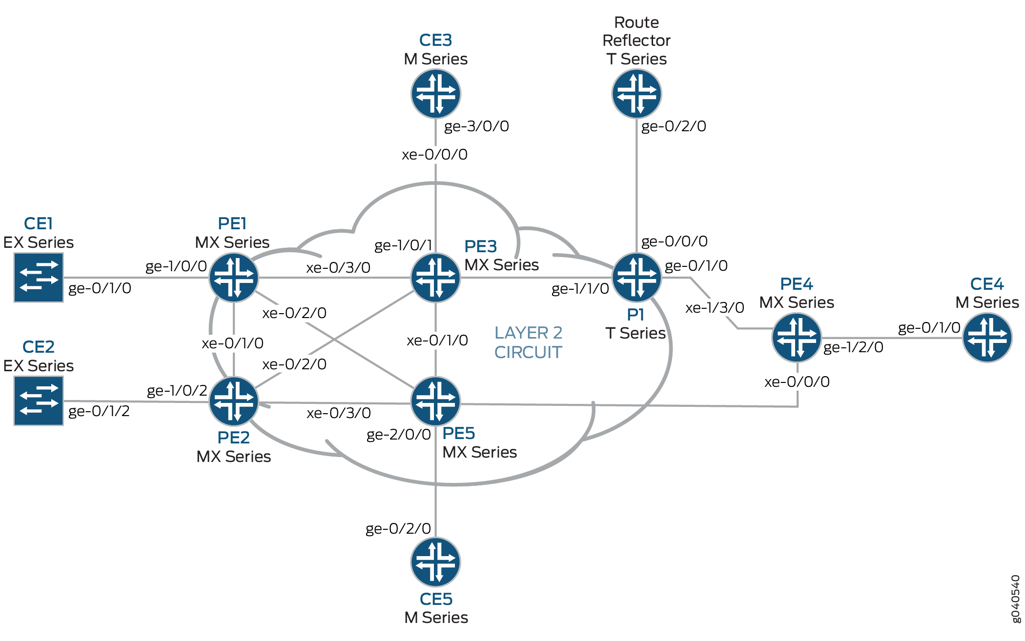
图 1 显示了第 2 层 VPN 到第 3 层 VPN 互连的物理拓扑。
第 2 层 VPN 到第 3 层 VPN 互连的逻辑拓扑如 图 2 所示。
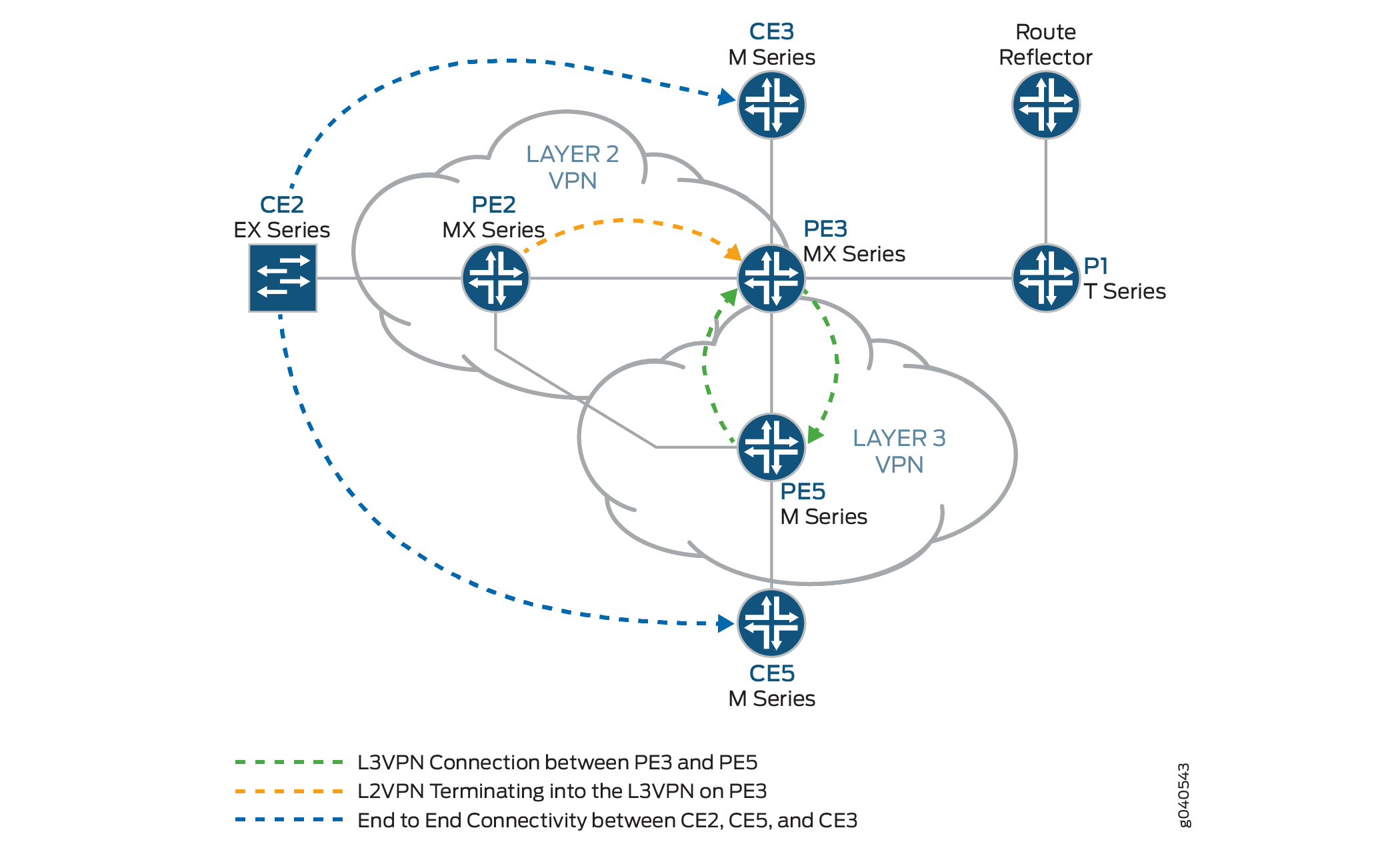 的第 2 层 VPN 的逻辑拓扑
以下定义描述了 图 1 和 图 2 中使用的器件缩写的含义。
-
客户边缘 (客户边缘) 设备 — 客户本地的设备,通过到一个或多个提供商边缘 (PE) 路由器的数据链路,提供对服务提供商 VPN 的访问。
通常,客户边缘设备是与其直连 PE 路由器建立邻接关系的 IP 路由器。建立邻接关系后,客户边缘路由器将站点的本地 VPN 路由播发至 PE 路由器,并从 PE 路由器获知远程 VPN 路由。
-
提供商边缘 (PE) 设备 - 位于提供商网络边缘的一台设备或一组设备,用于显示提供商对客户站点的视图。
PE 路由器与客户边缘路由器交换路由信息。PE 路由器可以识别通过它们连接的 VPN,并且 PE 路由器会维护 VPN 状态。PE 路由器仅需要为其直接连接到的 VPN 维护 VPN 路由。从 客户边缘 路由器学习本地 VPN 路由后,PE 路由器使用 IBGP 与其他 PE 路由器交换 VPN 路由信息。最后,当使用 MPLS 在提供商的骨干网中转发 VPN 数据流量时,入口 PE 路由器充当入口标签交换路由器(标签交换路由器),出口 PE 路由器充当出口标签交换路由器。
-
提供商 (P) 设备 — 在提供商的核心网络内运行且不直接与任何客户边缘连接的设备。
尽管 P 设备是为服务提供商的客户实施 VPN 的关键部分,并且可以为属于不同 VPN 的许多提供商操作的隧道提供路由,但它本身并不具有 VPN 感知能力,并且不会维护 VPN 状态。它的主要作用是允许服务提供商扩展其 VPN 产品,例如通过充当多个 PE 路由器的聚合点。
在 PE 路由器之间转发 VPN 数据流量时,P 路由器可充当 MPLS 传输 LSR。仅需要 P 路由器来维护到提供商的 PE 路由器的路由;他们不需要为每个客户站点维护特定的 VPN 路由信息。
配置
要将第 2 层 VPN 与第 3 层 VPN 互连,请执行以下操作:
配置基本协议和接口
分步程序
-
在每台 PE 和 P 路由器上,在所有接口上使用流量工程扩展配置 OSPF。在 fxp0.0 接口上禁用 OSPF。
[edit protocols] ospf { traffic-engineering; area 0.0.0.0 { interface all; interface fxp0.0 { disable; } } } -
在所有核心路由器上,在所有接口上启用 MPLS。禁用 fxp0.0 接口上的 MPLS。
[edit protocols] mpls { interface all; interface fxp0.0 { disable; } } -
在所有核心路由器上,创建一个内部 BGP 对等体组,并将路由反射器地址 (192.0.2.7) 指定为邻接方。此外,通过在层次结构级别包含
[edit protocols bgp group group-name family l2vpn]该语句,使signalingBGP 能够携带此对等方组的第 2 层 VPLS 网络层可达性信息 (NLRI) 消息。[edit protocols] bgp { group RR { type internal; local-address 192.0.2.2; family l2vpn { signaling; } neighbor 192.0.2.7; } } -
在路由器 PE3 上,创建内部 BGP 对等体组,并将路由反射器 IP 地址 (192.0.2.7) 指定为邻接方。启用 BGP 以传输此对等组的第 2 层 VPLS NLRI 消息,并通过在层次结构级别包含
[edit protocols bgp group group-name family inet-vpn]该语句来unicast启用 VPN-IPv4 地址处理。[edit protocols] bgp { group RR { type internal; local-address 192.0.2.3; family inet-vpn { unicast; } family l2vpn { signaling; } neighbor 192.0.2.7; } } -
对于路由器 PE3 和路由器 PE5 上的第 3 层 VPN 域,请在所有接口上启用 RSVP。在 fxp0.0 接口上禁用 RSVP。
[edit protocols] rsvp { interface all; interface fxp0.0 { disable; } } -
在路由器 PE3 和路由器 PE5 上,创建指向路由反射器和其他 PE 路由器的标签交换路径 (LSP)。以下示例显示了路由器 PE5 上的配置。
[edit protocols] mpls { label-switched-path to-RR { to 192.0.2.7; } label-switched-path to-PE2 { to 192.0.2.2; } label-switched-path to-PE3 { to 192.0.2.3; } label-switched-path to-PE4 { to 192.0.2.4; } label-switched-path to-PE1 { to 192.0.2.1; } } -
在路由器 PE1、PE2、PE3 和 PE5 上,使用 IPv4 地址配置核心接口,并启用 MPLS 地址家族。以下示例显示了路由器 PE2 上 xe-0/1/0 接口的配置。
[edit] interfaces { xe-0/1/0 { unit 0 { family inet { address 10.10.2.2/30; } family mpls; } } } -
在路由器 PE2 和路由器 PE3 上,为所有接口的第 2 层 VPN MPLS 信令协议配置 LDP。在 fxp0.0 接口上禁用 LDP。(也可以使用 RSVP。
[edit protocols] ldp { interface all; interface fxp0.0 { disable; } } -
在路由反射器上,创建内部 BGP 对等体组,并将 PE 路由器的 IP 地址指定为邻接方。
[edit] protocols { bgp { group RR { type internal; local-address 192.0.2.7; family inet { unicast; } family inet-vpn { unicast; } family l2vpn { signaling; } cluster 192.0.2.7; neighbor 192.0.2.1; neighbor 192.0.2.2; neighbor 192.0.2.4; neighbor 192.0.2.5; neighbor 192.0.2.3; } } } -
在路由反射器上,配置指向路由器 PE3 和 PE5 的 MPLS LSP,以解析来自 inet.3 路由表的 BGP 下一跃点。
[edit]
protocols {
    mpls {
        label-switched-path to-pe3 {
            to 192.0.2.3;
        }

        label-switched-path to-pe5 {
            to 192.0.2.5;
        }
        interface all;
    }
}
配置 VPN 接口
分步程序
路由器 PE2 是第 2 层 VPN 的一端。路由器 PE3 正在第 2 层 VPN 与第 3 层 VPN 之间执行第 2 层 VPN 拼接。路由器 PE3 使用在两个不同的第 2 层 VPN 实例下应用了不同逻辑接口单元配置的逻辑隧道接口(lt 接口)。数据包通过路由器 PE3 上配置的 lt 接口进行循环。路由器 PE5 的配置包含 PE-客户边缘接口。
-
在路由器 PE2 上,配置 ge-1/0/2 接口封装。包括封装语句,并在层次结构级别指定
ethernet-ccc[edit interfaces ge-1/0/2]选项(vlan-ccc也支持封装)。整个第 2 层 VPN 域(路由器 PE2 和 PE3)中的封装应相同。此外,配置接口 lo0。[edit] interfaces { ge-1/0/2 { encapsulation ethernet-ccc; unit 0; } lo0 { unit 0 { family inet { address 192.0.2.2/24; } } } } -
在路由器 PE2 上,在 [
edit routing-instances]层次结构级别配置路由实例。此外,在 [edit routing-instances routing-instances-name protocols]层次结构级别配置第 2 层 VPN 协议。将远程站点 ID 配置为 3。站点 ID 3 表示路由器 PE3 (Hub-PE)。第 2 层 VPN 使用 LDP 作为信令协议。请注意,在以下示例中,路由实例和协议都命名l2vpn为 。[edit] routing-instances {l2vpn{ # routing instance instance-type l2vpn; interface ge-1/0/2.0; route-distinguisher 65000:2; vrf-target target:65000:2; protocols {l2vpn{ # protocol encapsulation-type ethernet; site CE2 { site-identifier 2; interface ge-1/0/2.0 { remote-site-id 3; } } } } } } -
在路由器 PE5 上,为 PE-CE 链路
ge-2/0/0配置千兆客户边缘接口并配置该lo0接口。[edit interfaces] ge-2/0/0 { unit 0 { family inet { address 198.51.100.8/24; } } } lo0 { unit 0 { } } -
在路由器 PE5 上,在层次结构级别配置
[edit routing-instances]第 3 层 VPN 路由实例 (L3VPN)。还要在层次结构级别配置[edit routing-instances L3VPN protocols]BGP。[edit] routing-instances { L3VPN { instance-type vrf; interface ge-2/0/0.0; route-distinguisher 65000:5; vrf-target target:65000:2; vrf-table-label; protocols { bgp { group ce5 { neighbor 198.51.100.2 { peer-as 200; } } } } } } -
在 MX 系列路由器(如路由器 PE3)中,您必须创建要用于隧道服务的隧道服务接口。要创建隧道服务接口,请包含
bandwidth该语句,并在层次结构级别指定[edit chassis fpc slot-number pic slot-number tunnel-services]要为隧道服务预留的带宽量(以千兆位/秒为单位)。[edit] chassis { dump-on-panic; fpc 1 { pic 1 { tunnel-services { bandwidth 1g; } } } } -
在路由器 PE3 上,配置千兆以太网接口。
在层次结构级别包含
[edit interfaces ge-1/0/1.0 family inet]该address语句,并指定198.51.100.9/24为 IP 地址。[edit] interfaces { ge-1/0/1 { unit 0 { family inet { address 198.51.100.9/24; } } } } -
在路由器 PE3 上,在层次结构级别配置
lt-1/1/10.0[edit interfaces lt-1/1/10 unit 0]逻辑隧道接口。路由器 PE3 是使用逻辑隧道接口将第 2 层 VPN 拼接到第 3 层 VPN 的路由器。对等单元接口的配置是进行互连的要素。要配置接口,请包含
encapsulation该语句并指定该ethernet-ccc选项。包括该peer-unit语句,并将逻辑接口单元1指定为对等隧道接口。包括family该语句并指定该ccc选项。[edit] interfaces { lt-1/1/10 { unit 0 { encapsulation ethernet-ccc; peer-unit 1; family ccc; } } } -
在路由器 PE3 上,在层次结构级别配置
lt-1/1/10.1[edit interfaces lt-1/1/10 unit 1]逻辑隧道接口。要配置接口,请包含
encapsulation该语句并指定该ethernet选项。包括该peer-unit语句,并将逻辑接口单元0指定为对等隧道接口。包括family该语句并指定该inet选项。在层次结构级别包含[edit interfaces lt-1/1/10 unit 0]该address语句,并指定198.51.100.7/24为 IPv4 地址。[edit] interfaces { lt-1/1/10 { unit 1 { encapsulation ethernet; peer-unit 0; family inet { address 198.51.100.7/24; } } } } -
在路由器 PE3 上,将接口单元 1 添加到
lt层次结构级别的[edit routing-instances L3VPN]路由实例。将实例类型配置为 ASvrf,并将对等单元 1 配置lt为 PE-客户边缘接口,以将路由器 PE2 上的第 2 层 VPN 终止为路由器 PE3 上的第 3 层 VPN。[edit] routing-instances { L3VPN { instance-type vrf; interface ge-1/0/1.0; interface lt-1/1/10.1; route-distinguisher 65000:33; vrf-target target:65000:2; vrf-table-label; protocols { bgp { export direct; group ce3 { neighbor 198.51.100.10 { peer-as 100; } } } } } } -
在路由器 PE3 上,将接口单元 0 添加到
lt层次结构级别的[edit routing-instances protocols l2vpn]路由实例。此外,还要为第 2 层 VPN 和第 3 层 VPN 路由实例配置相同的 VRF 目标,以便路由可以在实例之间泄露。上一步中的示例配置显示了路由实例的L3VPNVRF 目标。以下示例显示了路由实例的l2vpnVRF 目标。[edit] routing-instances { l2vpn { instance-type l2vpn; interface lt-1/1/10.0; route-distinguisher 65000:3; vrf-target target:65000:2; protocols { l2vpn { encapsulation-type ethernet; site CE3 { site-identifier 3; interface lt-1/1/10.0 { remote-site-id 2; } } } } } } -
在路由器 PE3 上,配置该
policy-statement语句以将从直连lt接口单元 1 获知的路由导出到所有客户边缘路由器(如果需要)进行连接。[edit] policy-options { policy-statement direct { term 1 { from protocol direct; then accept; } } }
结果
以下输出显示了路由器 PE2 的完整配置:
路由器 PE2
interfaces {
    xe-0/1/0 {
        unit 0 {
            family inet {
                address 10.10.2.2/30;
            }
            family mpls;
        }
    }
    xe-0/2/0 {
        unit 0 {
            family inet {
                address 10.10.5.1/30;
            }
            family mpls;
        }
    }
    xe-0/3/0 {
        unit 0 {
            family inet {
                address 10.10.4.1/30;
            }
            family mpls;
        }
    }
    ge-1/0/2 {
        encapsulation ethernet-ccc;
        unit 0;
    }
    fxp0 {
        apply-groups [ re0 re1 ];
    }
    lo0 {
        unit 0 {
            family inet {
                address 192.0.2.2/24;
            }
        }
    }
}
routing-options {
    static {
        route 172.0.0.0/8 next-hop 172.19.59.1;
    }
    autonomous-system 65000;
}
protocols {
    mpls {
        interface all;
        interface fxp0.0 {
            disable;
        }
    }
    bgp {
        group RR {
            type internal;
            local-address 192.0.2.2;
            family l2vpn {
                signaling;
            }
            neighbor 192.0.2.7;
        }
    }
    ospf {
        traffic-engineering;
        area 0.0.0.0 {
            interface all;
            interface fxp0.0 {
                disable;
            }
        }
    }
    ldp {
        interface all;
        interface fxp0.0 {
            disable;
        }
    }
}
routing-instances {
    l2vpn {
        instance-type l2vpn;
        interface ge-1/0/2.0;
        route-distinguisher 65000:2;
        vrf-target target:65000:2;
        protocols {
            l2vpn {
                encapsulation-type ethernet;
                site CE2 {
                    site-identifier 2;
                    interface ge-1/0/2.0 {
                        remote-site-id 3;
                    }
                }
            }
        }
    }
}
以下输出显示了路由器 PE5 的最终配置:
路由器 PE5
interfaces {
    ge-0/0/0 {
        unit 0 {
            family inet {
                address 10.10.4.2/30;
            }
            family mpls;
        }
    }
    xe-0/1/0 {
        unit 0 {
            family inet {
                address 10.10.6.2/30;
            }
            family mpls;
        }
    }
    ge-1/0/0 {
        unit 0 {
            family inet {
                address 10.10.9.1/30;
            }
            family mpls;
        }
    }
    xe-1/1/0 {
        unit 0 {
            family inet {
                address 10.10.3.2/30;
            }
            family mpls;
        }
    }
    ge-2/0/0 {
        unit 0 {
            family inet {
                address 198.51.100.8/24;
            }
        }
    }
    lo0 {
        unit 0 {
            family inet {
                address 192.0.2.5/24;
            }
        }
    }
}
routing-options {
    static {
        route 172.0.0.0/8 next-hop 172.19.59.1;
    }
    autonomous-system 65000;
}
protocols {
    rsvp {
        interface all {
            link-protection;
        }
        interface fxp0.0 {
            disable;
        }
    }
    mpls {
        label-switched-path to-RR {
            to 192.0.2.7;
        }
        label-switched-path to-PE2 {
            to 192.0.2.2;
        }
        label-switched-path to-PE3 {
            to 192.0.2.3;
        }
        label-switched-path to-PE4 {
            to 192.0.2.4;
        }
        label-switched-path to-PE1 {
            to 192.0.2.1;
        }
        interface all;
        interface fxp0.0 {
            disable;
        }

    }
    bgp {
        group to-rr {
            type internal;
            local-address 192.0.2.5;
            family inet-vpn {
                unicast;
            }
            family l2vpn {
                signaling;
            }
            neighbor 192.0.2.7;
        }
    }
    ospf {
        traffic-engineering;
        area 0.0.0.0 {
            interface all;
            interface fxp0.0 {
                disable;
            }
        }
    }
    ldp {
        interface all;
        interface fxp0.0 {
            disable;
        }
    }
}
routing-instances {
    L3VPN {
        instance-type vrf;
        interface ge-2/0/0.0;
        route-distinguisher 65000:5;
        vrf-target target:65000:2;
        vrf-table-label;
        protocols {
            bgp {
                group ce5 {
                    neighbor 198.51.100.2 {
                        peer-as 200;
                    }
                }
            }
        }
    }
}
以下输出显示了路由器 PE3 的最终配置:
路由器 PE3
chassis {
    dump-on-panic;
    fpc 1 {
        pic 1 {
            tunnel-services {
                bandwidth 1g;
            }
        }
    }
    network-services ip;
}
interfaces {
    ge-1/0/1 {
        unit 0 {
            family inet {
                address 198.51.100.9/24;
            }
        }
    }
    lt-1/1/10 {
        unit 0 {
            encapsulation ethernet-ccc;
            peer-unit 1;
            family ccc;
        }
        unit 1 {
            encapsulation ethernet;
            peer-unit 0;
            family inet {
                address 198.51.100.7/24;
            }
        }
    }
    xe-2/0/0 {
        unit 0 {
            family inet {
                address 10.10.20.2/30;
            }
            family mpls;
        }
    }
    xe-2/1/0 {
        unit 0 {
            family inet {
                address 10.10.6.1/30;
            }
            family mpls;
        }
    }
    xe-2/2/0 {
        unit 0 {
            family inet {
                address 10.10.5.2/30;
            }
            family mpls;
        }
    }
    xe-2/3/0 {
        unit 0 {
            family inet {
                address 10.10.1.2/30;
            }
            family mpls;
        }
    }
    lo0 {
        unit 0 {
            family inet {
                address 192.0.2.3/24;
            }
        }
    }
}
routing-options {
    static {
        route 172.0.0.0/8 next-hop 172.19.59.1;
    }
    autonomous-system 65000;
}
protocols {
    rsvp {
        interface all;
        interface fxp0.0 {
            disable;
        }
    }
    mpls {
        label-switched-path to-RR {
            to 192.0.2.7;
        }
        label-switched-path to-PE2 {
            to 192.0.2.2;
        }
        label-switched-path to-PE5 {
            to 192.0.2.5;
        }
        label-switched-path to-PE4 {
            to 192.0.2.4;
        }
        label-switched-path to-PE1 {
            to 192.0.2.1;
        }
        interface all;
        interface fxp0.0 {
            disable;
        }
    }
    bgp {
        group RR {
            type internal;
            local-address 192.0.2.3;
            family inet-vpn {
                unicast;
            }
            family l2vpn {
                signaling;
            }
            neighbor 192.0.2.7;
        }
    }
    ospf {
        traffic-engineering;
        area 0.0.0.0 {
            interface all;
            interface fxp0.0 {
                disable;
            }
        }
    }
    ldp {
        interface all;
        interface fxp0.0 {
            disable;
        }
    }
}
policy-options {
    policy-statement direct {
        term 1 {
            from protocol direct;
            then accept;
        }
    }
}
routing-instances {
    L3VPN {
        instance-type vrf;
        interface ge-1/0/1.0;
        interface lt-1/1/10.1;
        route-distinguisher 65000:33;
        vrf-target target:65000:2;
        vrf-table-label;
        protocols {
            bgp {
                export direct;
                group ce3 {
                    neighbor 198.51.100.10 {
                        peer-as 100;
                    }
                }
            }
        }
    }
    l2vpn {
        instance-type l2vpn;
        interface lt-1/1/10.0;
        route-distinguisher 65000:3;
        vrf-target target:65000:2;
        protocols {
            l2vpn {
                encapsulation-type ethernet;
                site CE3 {
                    site-identifier 3;
                    interface lt-1/1/10.0 {
                        remote-site-id 2;
                    }
                }
            }
        }
    }
}
验证
验证第 2 层 VPN 到第 3 层 VPN 的互连:
验证路由器 PE2 VPN 接口
目的
检查第 2 层 VPN 是否已在路由器 PE2 接口上启动并正常工作,以及所有路由是否都已存在。
行动
-
使用命令
show l2vpn connections验证路由器 PE3 的连接站点 ID 是否为 3,并且状态是否为Up。user@PE2> show l2vpn connections Layer-2 VPN connections: Legend for connection status (St) EI -- encapsulation invalid NC -- interface encapsulation not CCC/TCC/VPLS EM -- encapsulation mismatch WE -- interface and instance encaps not same VC-Dn -- Virtual circuit down NP -- interface hardware not present CM -- control-word mismatch -> -- only outbound connection is up CN -- circuit not provisioned <- -- only inbound connection is up OR -- out of range Up -- operational OL -- no outgoing label Dn -- down LD -- local site signaled down CF -- call admission control failure RD -- remote site signaled down SC -- local and remote site ID collision LN -- local site not designated LM -- local site ID not minimum designated RN -- remote site not designated RM -- remote site ID not minimum designated XX -- unknown connection status IL -- no incoming label MM -- MTU mismatch MI -- Mesh-Group ID not available BK -- Backup connection ST -- Standby connection PF -- Profile parse failure PB -- Profile busy RS -- remote site standby Legend for interface status Up -- operational Dn -- down Instance: l2vpn Local site: CE2 (2) connection-site Type St Time last up # Up trans 3 rmt Up Jan 7 14:14:37 2010 1 Remote PE: 192.0.2.3, Negotiated control-word: Yes (Null) Incoming label: 800000, Outgoing label: 800001 Local interface: ge-1/0/2.0, Status: Up, Encapsulation: ETHERNET -
使用命令
show route table验证第 2 层 VPN 路由是否存在,以及是否存在通过该接口的xe-0/2/0.0下一跃点10.10.5.2。以下输出验证第 2 层 VPN 路由是否存在于 l2vpn.l2vpn.0 表中。对于路由器 PE3,应显示类似的输出。user@PE2> show route table l2vpn.l2vpn.0 l2vpn.l2vpn.0: 2 destinations, 2 routes (2 active, 0 holddown, 0 hidden) + = Active Route, - = Last Active, * = Both 65000:2:2:3/96 *[L2VPN/170/-101] 02:40:35, metric2 1 Indirect 65000:3:3:1/96 *[BGP/170] 02:40:35, localpref 100, from 192.0.2.7 AS path: I > to 10.10.5.2 via xe-0/2/0.0 -
验证路由器 PE2 是否具有指向路由器 PE3 的 LDP 标签的第 2 层 VPN MPLS 标签,该标签在两个方向(PUSH 和接入点)上都指向路由器 PE3。
user@PE2> show route table mpls.0
 mpls.0: 13 destinations, 13 routes (13 active, 0 holddown, 0 hidden)
+ = Active Route, - = Last Active, * = Both

0                  *[MPLS/0] 1w3d 08:57:41, metric 1
                      Receive
1                  *[MPLS/0] 1w3d 08:57:41, metric 1
                      Receive
2                  *[MPLS/0] 1w3d 08:57:41, metric 1
                      Receive
300560             *[LDP/9] 19:45:53, metric 1
                    > to 10.10.2.1 via xe-0/1/0.0, Pop
300560(S=0)        *[LDP/9] 19:45:53, metric 1
                    > to 10.10.2.1 via xe-0/1/0.0, Pop
301008             *[LDP/9] 19:45:53, metric 1
                    > to 10.10.4.2 via xe-0/3/0.0, Swap 299856
301536             *[LDP/9] 19:45:53, metric 1
                    > to 10.10.4.2 via xe-0/3/0.0, Pop
301536(S=0)        *[LDP/9] 19:45:53, metric 1
                    > to 10.10.4.2 via xe-0/3/0.0, Pop
301712             *[LDP/9] 16:14:52, metric 1
                    > to 10.10.5.2 via xe-0/2/0.0, Swap 315184
301728             *[LDP/9] 16:14:52, metric 1
                    > to 10.10.5.2 via xe-0/2/0.0, Pop
301728(S=0)        *[LDP/9] 16:14:52, metric 1
                    > to 10.10.5.2 via xe-0/2/0.0, Pop
800000             *[L2VPN/7] 02:40:35
                    > via ge-1/0/2.0, Pop       Offset: 4
ge-1/0/2.0         *[L2VPN/7] 02:40:35, metric2 1
                    > to 10.10.5.2 via xe-0/2/0.0, Push 800001 Offset: -4
意义
l2vpn路由实例在接口ge-1/0/2上运行,第 2 层 VPN 路由如表 l2vpn.l2vpn.0 中所示。表mpls.0显示了用于使用 LDP 标签转发流量的第 2 层 VPN 路由。
验证路由器 PE3 VPN 接口
目的
检查来自路由器 PE2 和路由器 PE3 的第 2 层 VPN 连接是否 Up 正常工作。
行动
-
验证是否已建立与家族
l2vpn-signaling和家族inet-vpn的路由反射器的 BGP 会话。user@PE3> show bgp summary Groups: 2 Peers: 2 Down peers: 0 Table Tot Paths Act Paths Suppressed History Damp State Pending bgp.l2vpn.0 1 1 0 0 0 0 bgp.L3VPN.0 1 1 0 0 0 0 Peer AS InPkt OutPkt OutQ Flaps Last Up/Dwn State|#Active /Received/Accepted/Damped... 192.0.2.7 65000 2063 2084 0 1 15:35:16 Establ bgp.l2vpn.0: 1/1/1/0 bgp.L3VPN.0: 1/1/1/0 L3VPN.inet.0: 1/1/1/0 l2vpn.l2vpn.0: 1/1/1/0
-
以下输出验证第 2 层 VPN 路由以及与之关联的标签。
user@PE3> show route table l2vpn.l2vpn.0 detail l2vpn.l2vpn.0: 2 destinations, 2 routes (2 active, 0 holddown, 0 hidden) 65000:2:2:3/96 (1 entry, 1 announced) *BGP Preference: 170/-101 Route Distinguisher: 65000:2 Next hop type: Indirect Next-hop reference count: 4 Source: 192.0.2.7 Protocol next hop: 192.0.2.2 Indirect next hop: 2 no-forward State: <Secondary Active Int Ext> Local AS: 65000 Peer AS: 65000 Age: 2:45:52 Metric2: 1 Task: BGP_65000.192.0.2.7+60585 Announcement bits (1): 0-l2vpn-l2vpn AS path: I (Originator) Cluster list: 192.0.2.7 AS path: Originator ID: 192.0.2.2 Communities: target:65000:2 Layer2-info: encaps:ETHERNET, control flags:Control-Word, mtu: 0, site preference: 100 Accepted Label-base: 800000, range: 2, status-vector: 0x0 Localpref: 100 Router ID: 192.0.2.7 Primary Routing Table bgp.l2vpn.0 -
以下输出显示了 mpls.0 路由表中的 L2VPN MPLS.0 路由。
user@PE3> show route table mpls.0 mpls.0: 21 destinations, 21 routes (21 active, 0 holddown, 0 hidden) + = Active Route, - = Last Active, * = Both 0 *[MPLS/0] 1w3d 09:05:41, metric 1 Receive 1 *[MPLS/0] 1w3d 09:05:41, metric 1 Receive 2 *[MPLS/0] 1w3d 09:05:41, metric 1 Receive 16 *[VPN/0] 15:59:24 to table L3VPN.inet.0, Pop 315184 *[LDP/9] 16:21:53, metric 1 > to 10.10.20.1 via xe-2/0/0.0, Pop 315184(S=0) *[LDP/9] 16:21:53, metric 1 > to 10.10.20.1 via xe-2/0/0.0, Pop 315200 *[LDP/9] 01:13:44, metric 1 to 10.10.20.1 via xe-2/0/0.0, Swap 625297 > to 10.10.6.2 via xe-2/1/0.0, Swap 299856 315216 *[LDP/9] 16:21:53, metric 1 > to 10.10.6.2 via xe-2/1/0.0, Pop 315216(S=0) *[LDP/9] 16:21:53, metric 1 > to 10.10.6.2 via xe-2/1/0.0, Pop 315232 *[LDP/9] 16:21:45, metric 1 > to 10.10.1.1 via xe-2/3/0.0, Pop 315232(S=0) *[LDP/9] 16:21:45, metric 1 > to 10.10.1.1 via xe-2/3/0.0, Pop 315248 *[LDP/9] 16:21:53, metric 1 > to 10.10.5.1 via xe-2/2/0.0, Pop 315248(S=0) *[LDP/9] 16:21:53, metric 1 > to 10.10.5.1 via xe-2/2/0.0, Pop 315312 *[RSVP/7] 15:02:40, metric 1 > to 10.10.6.2 via xe-2/1/0.0, label-switched-path to-pe5 315312(S=0) *[RSVP/7] 15:02:40, metric 1 > to 10.10.6.2 via xe-2/1/0.0, label-switched-path to-pe5 315328 *[RSVP/7] 15:02:40, metric 1 > to 10.10.20.1 via xe-2/0/0.0, label-switched-path to-RR 315360 *[RSVP/7] 15:02:40, metric 1 > to 10.10.20.1 via xe-2/0/0.0, label-switched-path to-RR 316272 *[RSVP/7] 01:13:27, metric 1 > to 10.10.6.2 via xe-2/1/0.0, label-switched-path Bypass->10.10.9.1 316272(S=0) *[RSVP/7] 01:13:27, metric 1 > to 10.10.6.2 via xe-2/1/0.0, label-switched-path Bypass->10.10.9.1 800001 *[L2VPN/7] 02:47:33 > via lt-1/1/10.0, Pop Offset: 4 lt-1/1/10.0 *[L2VPN/7] 02:47:33, metric2 1 > to 10.10.5.1 via xe-2/2/0.0, Push 800000 Offset: -4 -
将命令
show route table mpls.0与查看路由的 BGP 属性(如下一跃点类型和标签操作)选项一起使用detail。user@PE5> show route table mpls.0 detail lt-1/1/10.0 (1 entry, 1 announced) *L2VPN Preference: 7 Next hop type: Indirect Next-hop reference count: 2 Next hop type: Router, Next hop index: 607 Next hop: 10.10.5.1 via xe-2/2/0.0, selected Label operation: Push 800000 Offset: -4 Protocol next hop: 192.0.2.2 Push 800000 Offset: -4 Indirect next hop: 8cae0a0 1048574 State: <Active Int> Age: 2:46:34 Metric2: 1 Task: Common L2 VC Announcement bits (2): 0-KRT 2-Common L2 VC AS path: I Communities: target:65000:2 Layer2-info: encaps:ETHERNET, control flags:Control-Word, mtu: 0, site preference: 100
验证从路由器 CE2 到路由器 CE5 和路由器 CE3 的端到端连接
目的
检查路由器 CE2、CE3 和 CE5 之间的连接。
行动
-
从路由器 CE2 Ping 路由器 CE3 IP 地址。
user@CE2> ping 198.51.100.10 # CE3 IP address
PING 198.51.100.10 (198.51.100.10): 56 data bytes
64 bytes from 198.51.100.10: icmp_seq=0 ttl=63 time=0.708 ms
64 bytes from 198.51.100.10: icmp_seq=1 ttl=63 time=0.610 ms
-
Ping 来自路由器 CE2 的路由器 CE5 IP 地址。
user@CE2> ping 198.51.100.2 # CE5 IP address
PING 198.51.100.2 (198.51.100.2): 56 data bytes
64 bytes from 198.51.100.2: icmp_seq=0 ttl=62 time=0.995 ms
64 bytes from 198.51.100.2: icmp_seq=1 ttl=62 time=1.005 ms