基本 MPLS 配置
MPLS 配置概述
首次在设备上安装 Junos OS 时,默认情况下会禁用 MPLS。您必须将设备显式配置为允许 MPLS 流量通过。对于 MPLS 网络中运行 Junos OS 的所有设备,请完成以下步骤。
要启用 MPLS:
当数据包转发模式更改为 MPLS 时,所有基于流的安全功能都将停用,并且设备仅执行基于数据包的处理。基于流的服务(如安全策略、区域、NAT、ALG、机箱群集、筛选、防火墙身份验证和 IPsec VPN)在设备上不可用。但是,在基于流的数据包转发模式下,可使用防火墙过滤器为所选流量启用 MPLS。
MPLS 配置准则
在 QFX 系列设备或 EX4600 上配置 MPLS 时,请注意,支持的 IP 前缀数量取决于所使用的特定平台。有关更多信息,请参阅设备数据表中的秤规格。
-
我们建议采取以下措施:
-
如果您的入口提供商边缘 (PE) 交换机需要支持超过 8000 个外部 IP 前缀,请使用更大容量的设备作为入口 PE 交换机。
-
如果将交换机用作 BGP 标记路由的路由反射器,请将其用作专用路由反射器(即交换机不得参与数据流量管理)。
-
如果将交换机用作 PE 交换机或用作 BGP 标记路由的路由反射器,请在 PE 交换机和路由反射器上配置路由策略,以从路由表过滤外部 IP 路由。
下面给出了名为 fib_policy 的路由策略(在
[edit policy-options和[edit routing-options层次结构级别)的配置示例,用于过滤 inet.0 路由表中的BGP标记路由:user@switch# show policy-options policy-statement fib_policy { from { protocol bgp; rib inet.0; } then reject; }user@switch# show routing-options forwarding-table { export fib_policy; }
-
-
QFX 系列设备或 EX4600 交换机不支持在层次结构级别使用
[edit protocols mpls path-mtu]该语句进行allow-fragmentation数据包分段。因此,您必须确保每个 MPLS 接口上配置的最大传输单元 (MTU) 值足以处理 MPLS 数据包。大小超过接口 MTU 值的数据包将被丢弃。
配置 MPLS
您还必须配置 MPLS 才能使第 2 层 交叉连接正常工作。以下是最小的 MPLS 配置:
[edit]
interfaces {
                                    interface-name                {
        unit                  logical-unit-number;
    }
}
protocols {
    mpls {
        interface all;
    }
}
示例:启用 MPLS
此示例说明如何启用 MPLS 进行基于数据包的处理。它还演示了如何在网络中的所有传输接口上启用 MPLS 系列和 MPLS 进程。
要求
开始之前,请删除所有已配置的安全服务。请参阅 示例:删除安全性服务。
概述
本主题中的说明介绍如何在设备上启用 MPLS。必须先在设备上启用 MPLS,然后才能将运行 Junos OS 的设备纳入 MPLS 网络。
配置
过程
CLI 快速配置
要快速配置此示例,请复制以下命令,将其粘贴到文本文件中,删除所有换行符,更改详细信息,以便与网络配置匹配,将命令复制并粘贴到层次结构级别的 [edit] CLI 中,然后从配置模式进入。commit
set interfaces ge-1/0/0 unit 0 family mpls
set protocols mpls ge-1/0/0 unit 0
分步程序
下面的示例要求您在各个配置层级中进行导航。有关操作说明,请参阅在 配置模式下使用 CLI 编辑器。
要启用 MPLS:
-
在要包含在 MPLS 网络中的每个传输接口上启用 MPLS 家族。
[edit interfaces]
user@host# set interfaces ge-1/0/0 unit 0 family mpls
-
在 MPLS 网络中的所有中转接口上启用 MPLS 进程。
[edit protocols mpls]
user@host# set interface ge-1/0/0 unit 0
-
此外,对于安全设备,请启用 MPLS 进行 基于数据包的 处理。对于路由和交换设备,跳过此步骤。
[edit security forwarding-options]
user@host# set family mpls mode packet-based
注意:启用 MPLS 后,所有基于流的安全功能都将停用,设备将执行基于数据包的处理。基于流的服务(如安全策略、区域、NAT、ALG、机箱群集、筛选、防火墙身份验证、IP 数据包和 IPsec VPN)在设备上不可用。
从流模式切换到数据包模式之前,必须移除流模式下剩余的所有安全策略。为防止管理连接丢失,您必须将管理接口绑定到各区域并启用主机入站流量,以防止设备断开连接。
有关配置区域的信息,请参阅《 安全性设备安全性策略用户指南》。
结果
如果完成设备配置,请从配置模式进入。commit
验证
确认配置工作正常。
验证基于数据包的处理是否已启用
目的
对于特定于安全设备,请验证是否启用了基于数据包的处理。
行动
在操作模式下,输入命令 show security forwarding-options 。
user@host> show security forwarding-options
family {
    mpls {
        mode packet-based;
    }
}
如果使用命令 set security forward-option family mpls mode packet启用 MPLS 以进行基于数据包的处理,则模式不会立即更改,系统将显示以下消息:
警告:尝试重置流模式时可能需要重新启动
警告:尝试重置 MPLS 流模式时可能需要重新启动,请检查安全流状态以获取详细信息。
您需要重新启动设备才能使配置生效。
如果禁用 MPLS 并切换回使用安全服务(基于流的处理),模式将不会立即更改,并且系统将显示警告消息,指示您重新启动设备。您必须重新启动设备才能使配置生效。这也将导致管理会话被重置,传输流量被中断。
示例:在 EX8200 和 EX4500 交换机上配置 MPLS
您可以在交换机上配置 MPLS,以提高网络中的传输效率。MPLS 服务可用于将各个站点连接到骨干网络,并确保低延迟应用(例如基于 IP 的语音 (VoIP))和其他关键业务功能)获得更好的性能。
要在交换机上实施 MPLS,您必须配置两台提供商边缘 (PE) 交换机(一台入口 PE 交换机和一台出口 PE 交换机)和至少一台提供商(中转)交换机。您可以将 MPLS 网络 PE 交换机上的客户边缘 (客户边缘) 接口配置为电路交叉连接 (CCC) 或 IP(系列 inet)接口。
此示例说明如何使用简单接口作为 CCC 配置 MPLS 隧道:
此示例说明如何使用简单接口作为 CCC 配置 MPLS。有关将标记的 VLAN 接口配置为 CCC 的信息,请参阅 使用第 2 层 VPN 配置基于 MPLS 的 VLAN CCC(CLI 过程) 或 使用第 2 层电路配置基于 MPLS 的 VLAN CCC。
要求
此示例使用以下硬件和软件组件:
-
交换机安装 Junos OS 10.1 或更高版本
-
三台 EX 系列交换机
开始配置 MPLS 之前,请确保已在核心接口上配置路由协议(OSPF 或 IS-IS),并在所有交换机上配置环路接口。此示例包括在所有交换机上配置 OSPF。有关将 IS-IS 配置为路由协议的信息,请参阅 Junos OS 路由协议配置指南。
概述和拓扑
此示例包括一台入口或本地 PE 交换机、一台出口或远程 PE 交换机以及一台提供商交换机。它包括将本地 PE 交换机 (PE-1) 的客户边缘接口连接到远程 PE 交换机 (PE-2) 的客户边缘接口的 CCC。它还介绍了如何配置 PE 交换机和提供商交换机的核心接口以支持 MPLS 数据包的传输。在此示例中,连接本地 PE 交换机和提供商交换机的核心接口是单独的接口,而连接远程 PE 交换机和提供商交换机的核心接口是聚合以太网接口。
-
核心接口不能标记为 VLAN 接口。
-
核心接口可以是聚合以太网接口。此示例包括提供商交换机和远程 PE 交换机之间的 LAG,因为这种类型的配置是您可以实施的另一个选项。有关配置 LAG 的信息,请参阅配置聚合以太网链路(CLI 过程)。
图 1 显示了此示例中使用的拓扑。
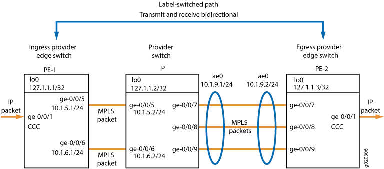 上配置 MPLS
表 1 显示了此示例中用于入口 PE 交换机的 MPLS 配置组件。
|
属性 |
设置 |
描述 |
|---|---|---|
|
本地 PE 交换机硬件 |
EX 系列交换机 |
PE-1 |
|
环路地址 |
lo0 127.1.1.1/32 |
标识用于交换机间通信的 PE-1。 |
|
路由协议 |
OSPF 流量工程 |
指示此交换机正在使用 OSPF 作为路由协议,并且流量工程已启用。 |
|
MPLS 协议和标签交换路径的定义 |
MPLS 的比较 标签交换路径lsp_to_pe2_ge1 到 127.1.13 |
指示此 PE 交换机正在使用带有指定 LSP 的 MPLS 协议来到达另一台 PE 交换机(由环路地址指定)。 该语句还必须指定用于 MPLS 流量的核心接口。 |
|
回复 |
回复 |
指示此交换机正在使用 RSVP。该语句必须指定环路地址和将用于 RSVP 会话的核心接口。 |
|
接口系列 |
Family INET MPLS 系列 家族 CCC |
核心接口的逻辑单元配置为同时属于 家族 inet 和 家族 mpls。 客户边缘接口的逻辑单元配置为属于 ccc 家族。 |
|
客户边缘接口 |
ge-0/0/1 |
将此网络连接到网络外部设备的接口。 |
|
核心接口 |
ge-0/0/5.0 和 ge-0/0/6.0,IP 地址为 10.1.5.1/24 和 10.1.6.1/24 |
连接到 MPLS 网络内其他交换机的接口。 |
|
CCC 定义 |
连接远程接换机 GE-1 到 PE2 接口 ge-0/0/1.0 传输 LSP lsp_to_pe2_ge1接收 LSP lsp_to_pe1_ge1 |
将电路交叉连接 (CCC) ge-0/0/1 与本地和远程 PE 交换机上定义的 LSP 相关联。 |
表 2 显示了此示例中用于出口 PE 交换机的 MPLS 配置组件。
|
属性 |
设置 |
描述 |
|---|---|---|
|
远程 PE 交换机硬件 |
EX 系列交换机 |
PE-2 |
|
环路地址 |
lo0 127.1.1.3/32 |
标识用于交换机间通信的 PE-2。 |
|
路由协议 |
OSPF 流量工程 |
指示此交换机正在使用 OSPF 作为路由协议,并且流量工程已启用。 |
|
MPLS 协议和标签交换路径的定义 |
MPLS 的比较 标签交换路径lsp_to_pe1_ge1 到 127.1.1.1 |
指示此 PE 交换机正在使用具有指定标签交换路径 (LSP) 的 MPLS 协议来到达另一台 PE 交换机。 该语句还必须指定用于 MPLS 流量的核心接口。 |
|
回复 |
回复 |
指示此交换机正在使用 RSVP。该语句必须指定环路地址和将用于 RSVP 会话的核心接口。 |
|
接口系列 |
Family INET MPLS 系列 家族 CCC |
核心接口的逻辑单元配置为同时属于 家族 inet 和 家族 mpls。 客户边缘接口的逻辑单元配置为属于 ccc 家族。 |
|
客户边缘接口 |
ge-0/0/1 |
将此网络连接到网络外部设备的接口。 |
|
核心接口 |
ae0,IP 地址为 10.1.9.2/24 |
PE-2 上的聚合以太网接口,连接到提供商交换机的聚合以太网接口 ae0 ,属于 家族 MPLS。 |
|
CCC 定义 |
连接远程接换机 ge-1-to-pe1 接口 ge-0/0/1.0 传输 LSP lsp_to_pe1_ge1;接收 LSP lsp_to_pe2_ge1; |
将 CCC ge-0/0/1 与本地和远程 PE 交换机上定义的 LSP 相关联。 |
表 3 显示了此示例中用于提供商交换机的 MPLS 配置组件。
|
属性 |
设置 |
描述 |
|---|---|---|
|
提供商交换机硬件 |
EX 系列交换机 |
MPLS 网络配置中的中转交换机。 |
|
环路地址 |
lo0 127.1.1.2/32 |
确定用于交换机间通信的提供商交换机。 |
|
路由协议 |
OSPF 流量工程 |
指示此交换机正在使用 OSPF 作为路由协议,并且流量工程已启用。 |
|
MPLS 协议 |
MPLS 的比较 |
指示此交换机正在使用 MPLS 协议。 该语句必须指定将用于 MPLS 流量的核心接口。 |
|
回复 |
回复 |
指示此交换机正在使用 RSVP。该语句必须指定将用于 RSVP 会话的环路和核心接口。 |
|
接口系列 |
Family INET MPLS 系列 |
环路接口和核心接口的逻辑单元属于 家族 inet。 核心接口的逻辑单元也配置为属于 家族 MPLS。 |
|
核心接口 |
ge-0/0/5.0 和 ge-0/0/6.0,IP 地址为 10.1.5.1/24 和 10.1.6.1/24,ae0,IP 地址为 10.1.9.1/24 |
将提供商交换机 (P) 连接到 PE-1 的接口。 P 上的聚合以太网接口,连接到 PE-2 的聚合以太网接口 ae0 。 |
配置本地 PE 交换机
过程
CLI 快速配置
要快速配置本地入口 PE 交换机,请将以下命令复制粘贴到 PE-1 的交换机终端窗口中:
[edit]
                         set protocols ospf traffic-engineering
                         set protocols ospf area 0.0.0.0 interface lo0.0
                         set protocols ospf area 0.0.0.0 interface ge-0/0/5.0
                         set protocols ospf area 0.0.0.0 interface ge-0/0/6.0
                         set protocols mpls label-switched-path lsp_to_pe2_ge1 to 127.1.1.3
                         set protocols mpls interface ge-0/0/5.0
                         set protocols mpls interface ge-0/0/6.0
                         set protocols rsvp interface lo0.0
                         set protocols rsvp interface ge-0/0/5.0
                         set protocols rsvp interface ge-0/0/6.0
                         set interfaces lo0 unit 0 family inet address 127.1.1.1/32
                         set interfaces ge-0/0/5 unit 0 family inet address 10.1.5.1/24
                         set interfaces ge-0/0/6 unit 0 family inet address 10.1.6.1/24
                         set interfaces ge-0/0/5 unit 0 family mpls
                         set interfaces ge-0/0/6 unit 0 family mpls
                         set interfaces ge-0/0/1 unit 0 family ccc
                         set protocols connections remote-interface-switch ge-1-to-pe2 interface ge-0/0/1.0
                         set protocols connections remote-interface-switch ge-1-to-pe2 transmit-lsp lsp_to_pe2_ge1
                         set protocols connections remote-interface-switch ge-1-to-pe2 receive-lsp lsp_to_pe1_ge1
分步程序
要配置本地入口 PE 交换机,请执行以下操作:
-
在启用流量工程的情况下配置 OSPF:
[edit protocols]
user@switchPE-1# set ospf traffic-engineering
-
在环路地址和核心接口上配置 OSPF:
[edit protocols] user@switchPE-1# set ospf area 0.0.0.0 interface lo0.0 user@switchPE-1# set ospf area 0.0.0.0 interface ge-0/0/5.0 user@switchPE-1# set ospf area 0.0.0.0 interface ge-0/0/6.0 -
在此 PE 交换机 (PE-1) 上配置 MPLS,并使用到另一台 PE 交换机 (PE-2) 的标签交换路径 (LSP):
[edit protocols] user@switchPE-1# set mpls label-switched-path lsp_to_pe2_ge1 to 127.1.1.3 -
在核心接口上配置 MPLS:
[edit protocols] user@switchPE-1# set mpls interface ge-0/0/5.0 user@switchPE-1# set mpls interface ge-0/0/6.0 -
在环路接口和核心接口上配置 RSVP:
[edit protocols] user@switchPE-1# set rsvp interface lo0.0 user@switchPE-1# set rsvp interface ge-0/0/5.0 user@switchPE-1# set rsvp interface ge-0/0/6.0 -
为环路接口和核心接口配置 IP 地址:
[edit]
user@switchPE-1# set interfaces lo0 unit 0 family inet address 127.1.1.1/32
user@switchPE-1# set interfaces ge-0/0/5 unit 0 family inet address 10.1.5.1/24
user@switchPE-1# set interfaces ge-0/0/6 unit 0 family inet address 10.1.6.1/24
-
在核心接口地址的逻辑单元上配置 家族 MPLS :
[edit]
user@switchPE-1# set interfaces ge-0/0/5 unit 0 family mpls
user@switchPE-1# set interfaces ge-0/0/6 unit 0 family mpls
-
将客户边缘接口的逻辑单元配置为 CCC:
[edit interfaces ge-0/0/1 unit 0]
-user@PE-1# set family ccc
-
配置从 PE-1 到 PE-2 的基于接口的 CCC:
注意:您还可以将标记的 VLAN 接口配置为 CCC。请参阅 使用第 2 层 VPN 配置基于 MPLS 的 VLAN CCC(CLI 过程) 或 使用第 2 层电路配置基于 MPLS 的 VLAN CCC。
[edit protocols]
user@PE-1# set connections                                 remote-interface-switch ge-1-to-pe2 interface ge-0/0/1.0
user@PE-1# set connections remote-interface-switch ge-1-to-pe2 transmit-lsp lsp_to_pe2_ge1
user@PE-1# set connections remote-interface-switch ge-1-to-pe2 receive-lsp lsp_to_pe1_ge1
结果
显示配置结果:
user@switchPE-1> show configuration
interfaces {
    ge-0/0/1 {
        unit 0 {
            family ccc;
        }
    }
    ge-0/0/5 {
        unit 0 {
            family inet {
                address 10.1.5.1/24;
            }
            family mpls;
        }
    }
    ge-0/0/6 {
        unit 0 {
            family inet {
                address 10.1.6.1/24;
            }
            family mpls;
        }
    }
    lo0 {
        unit 0 {
            family inet {
                address 127.1.1.1/32;
            }
        }
    }
protocols {
    rsvp {
        interface lo0.0;
        interface ge-0/0/5.0;
        interface ge-0/0/6.0;
    }
    mpls {
        label-switched-path lsp_to_pe2_ge1 {
            to 127.1.1.3;
        }
        interface ge-0/0/5.0;
        interface ge-0/0/6.0;
    }
    ospf {
        traffic-engineering;
        area 0.0.0.0 {
            interface lo0.0;
            interface ge-0/0/5.0;
            interface ge-0/0/6.0;
        }
    }
    connections {
        remote-interface-switch ge-1-to-pe2 {
            interface ge-0/0/1.0;
            transmit-lsp lsp_to_pe2_ge1;
            receive-lsp lsp_to_pe1_ge1;
        }
    }
配置远程 PE 交换机
过程
CLI 快速配置
要快速配置远程 PE 交换机,请将以下命令复制粘贴到 PE-2 的交换机终端窗口中:
[edit]
                         set protocols ospf traffic-engineering
                         set protocols ospf area 0.0.0.0 interface lo0.0
                         set protocols ospf area 0.0.0.0 interface ae0
                         set protocols mpls label-switched-path lsp_to_pe1_ge1 to 127.1.1.1
                         set protocols mpls interface ae0
                         set protocols rsvp interface lo0.0
                         set protocols rsvp interface ae0
                         set interfaces lo0 unit 0 family inet address 127.1.1.3/32
                         set interfaces ae0 unit 0 family inet address 10.1.9.2/24
                         set interfaces ae0 unit 0 family mpls
                         set interfaces ge-0/0/1 unit 0 family ccc
                         set protocols connections remote-interface-switch ge-1-to-pe1 interface ge-0/0/1.0
                         set protocols connections remote-interface-switch ge-1-to-pe1 transmit-lsp lsp_to_pe1_ge1
                         set protocols connections remote-interface-switch ge-1-to-pe1 receive-lsp lsp_to_pe2_ge1
分步程序
要配置远程 PE 交换机 (PE-2),请执行以下操作:
-
在启用流量工程的情况下配置 OSPF:
[edit protocols]
user@switchPE-2# set ospf traffic-engineering
-
在环路接口和核心接口上配置 OSPF:
[edit protocols] user@switchPE-2# set ospf area 0.0.0.0 interface lo0.0 user@switchPE-2# set ospf area 0.0.0.0 interface ae0 -
在此交换机 (PE-2) 上配置 MPLS,其中包含到另一台 PE 交换机 (PE-1) 的标签交换路径 (LSP):
[edit protocols] user@switchPE-2# set mpls label-switched-path lsp_to_pe1_ge1 to 127.1.1.1 -
在核心接口上配置 MPLS:
[edit protocols]
user@switchPE-2# set mpls interface ae0
-
在环路接口和核心接口上配置 RSVP:
[edit protocols]
ser@switchPE-2# set rsvp interface lo0.0
user@switchPE-2# set rsvp interface ae0
-
为环路接口和核心接口配置 IP 地址:
[edit]
user@switchPE-2# set interfaces lo0 unit 0 family inet address 127.1.1.3/32
user@switchPE-2# set interfaces ae0 unit 0 family inet address 10.1.9.2/24
-
在核心接口的逻辑单元上配置 家族 MPLS :
[edit] user@switchPE-2# set interfaces ae0 unit 0 family mpls -
将客户边缘接口的逻辑单元配置为 CCC:
[edit interfaces ge-0/0/1 unit 0]
user@PE-2# set family ccc
-
配置从 PE-2 到 PE-1 的基于接口的 CCC:
[edit protocols]
user@PE-2# set connections remote-interface-switch ge-1-to-pe1 interface ge-0/0/1.0
user@PE-2# set connections remote-interface-switch ge-1-to-pe1 transmit-lsp lsp_to_pe1_ge1
user@PE-2# set connections remote-interface-switch ge-1-to-pe1 receive-lsp lsp_to_pe2_ge1
结果
显示配置结果:
user@switchPE-2> show configuration
interfaces {
    ge-0/0/1 {
        unit 0 {
            family ccc;
        }
    }
    ae0 {
        unit 0 {
            family inet {
                address 10.1.9.2/24;
            }
            family mpls;
        }
    }
    lo0 {
        unit 0 {
            family inet {
                address 127.1.1.3/32;
            }
        }
    }
}
protocols {
    rsvp {
        interface lo0.0;
        interface ae0.0;
    }
    mpls {
        label-switched-path lsp_to_pe1_ge1 {
            to 127.1.1.1;
        }
        interface ae0.0;
    }
    ospf {
        traffic-engineering;
        area 0.0.0.0 {
            interface ae0.0;
        }
    }
    connections {
        remote-interface-switch ge-1-to-pe1 {
            interface ge-0/0/1.0;
            transmit-lsp lsp_to_pe1_ge1;
            receive-lsp lsp_to_pe2_ge1;
        }
    }
}
配置提供商交换机
过程
CLI 快速配置
要快速配置提供商交换机,请复制以下命令并将其粘贴到交换机终端窗口中:
     [edit]
                         set  protocols ospf traffic-engineering
                         set protocols ospf area 0.0.0.0 interface lo0.0
                         set protocols ospf area 0.0.0.0  interface ge-0/0/5.0
                         set protocols ospf area 0.0.0.0  interface ge-0/0/6.0
                         set protocols ospf area 0.0.0.0  interface ae0
                         set protocols mpls interface ge-0/0/5.0
                         set protocols mpls interface ge-0/0/6.0
                         set protocols mpls interface ae0
                         set protocols rsvp interface lo0.0
                         set protocols rsvp interface ge-0/0/5.0
                         set protocols rsvp interface ge-0/0/6.0
                         set protocols rsvp interface ae0
                         set interfaces lo0 unit 0 family inet address 127.1.1.2/32
                         set interfaces ge-0/0/5 unit 0 family inet address 10.1.5.1/24
                         set interfaces ge-0/0/6 unit 0 family inet address 10.1.6.1/24
                         set interfaces ae0 unit 0 family inet address 10.1.9.1/24
                         set interfaces ge-0/0/5 unit 0 family mpls
                         set interfaces ge-0/0/6 unit 0 family mpls
                         set interfaces ae0 unit 0 family mpls
分步程序
要配置提供商交换机,请执行以下操作:
-
在启用流量工程的情况下配置 OSPF:
[edit protocols]
user@switchP# set ospf traffic-engineering
-
在环路接口和核心接口上配置 OSPF:
[edit protocols]
user@switchP# set ospf area 0.0.0.0 interface lo0.0
user@switchP# set ospf area 0.0.0.0 interface ge-0/0/5
user@switchP# set ospf area 0.0.0.0 interface ge-0/0/6
user@switchP# set ospf area 0.0.0.0 interface ae0
-
在交换机上的核心接口上配置 MPLS:
[edit protocols]
user@switchP# set mpls interface ge-0/0/5
user@switchP# set mpls interface ge-0/0/6
user@switchP# set mpls interface ae0
-
在环路接口和核心接口上配置 RSVP:
[edit protocols] user@switchP# set rsvp interface lo0.0 user@switchP# set rsvp interface ge-0/0/5 user@switchP# set rsvp interface ge-0/0/6 user@switchP# set rsvp interface ae0 -
为环路接口和核心接口配置 IP 地址:
[edit]
user@switchP# set interfaces lo0 unit 0 family inet address 127.1.1.2/32
user@switchP# set interfaces ge-0/0/5 unit 0 family inet address 10.1.5.1/24
user@switchP# set interfaces ge-0/0/6 unit 0 family inet address 10.1.6.1/24
user@switchP# set interfaces ae0 unit 0 family inet address 10.1.9.1/24
-
在核心接口地址的逻辑单元上配置 家族 MPLS :
[edit]
user@switchP# set interfaces ge-0/0/5 unit 0 family mpls
user@switchP# set interfaces ge-0/0/6 unit 0 family mpls
user@switchP# set interfaces ae0 unit 0 family mpls
结果
显示配置结果:
user@switchP> show configuration
interfaces {
    ge-0/0/5 {
        unit 0 {
            family inet {
                address 10.1.5.1/24;
            }
            family mpls;
            }
        }
    ge-0/0/6 {
        unit 0 {
            family inet {
                address 10.1.6.1/24;
            }
            family mpls;
            }
        }
    }
    ae0 {
        unit 0 {
            family inet {
                address 10.1.9.1/24;
            }
            family mpls;
        }
    }
    lo0 {
        unit 0 {
            family inet {
                address 127.1.1.2/32;
            }
        }
    }
protocols {
    rsvp {
        interface lo0.0;
        interface ge-0/0/5.0;
        interface ge-0/0/6.0;
        interface ae0.0;
    }
    mpls {
        interface ge-0/0/5.0;
        interface ge-0/0/6.0;
        interface ae0.0;
    }
    ospf {
        traffic-engineering;
        area 0.0.0.0 {
            interface lo0.0;
            interface ge-0/0/5.0;
            interface ge-0/0/6.0;
            interface ae0.0;
        }
    }
验证
要确认配置工作正常,请执行以下任务:
验证交换机上的物理层
目的
验证接口是否已开启。在每台交换机上执行此验证任务。
行动
user@switchPE-1> show interfaces terse

Interface               Admin Link Proto    Local                 Remote
ge-0/0/0                up    up
ge-0/0/0.0              up    up  eth-switch
ge-0/0/1                up    up
ge-0/0/1.0              up    up  ccc
ge-0/0/2                up    up
ge-0/0/2.0              up    up  eth-switch
ge-0/0/3                up    up
ge-0/0/3.0              up    up eth-switch
ge-0/0/4                up    up
ge-0/0/4.0              up    up eth-switch
ge-0/0/5                up    up
ge-0/0/5.0              up    up inet     10.1.5.1/24
                                 mpls
ge-0/0/6                up    up
ge-0/0/6.0              up    up inet     10.1.6.1/24
                                 mpls
意义
该 show interfaces terse 命令显示有关交换机上千兆以太网接口的状态信息。此输出验证接口是否 已开启。协议家族的输出(Proto 列)显示接口 ge-0/0/1.0 配置为电路交叉连接。核心接口的协议家族(ge-0/0/5.0 和 ge-0/0/6.0)的输出显示,这些接口同时配置为 inet 和 mpls。核心接口的 本地 列显示为这些接口配置的 IP 地址。
验证路由协议
目的
验证配置的路由协议的状态。在每台交换机上执行此验证任务。状态必须为 Full。
行动
user@switchPE-1> show ospf neighbor

Address          Interface              State     ID               Pri  Dead
127.1.1.2          ge—0/0/5              Full     10.10.10.10      128    39
意义
命令 show ospf neighbor 显示路由协议的状态。此输出显示状态为 Full,表示路由协议运行正常,也就是说,hello 数据包正在直接连接的邻接方之间交换。
验证用于 MPLS 流量的核心接口
目的
验证 MPLS 接口的状态是否为 “已启动”。在每台交换机上执行此验证任务。
行动
user@switchPE-1>                              show mpls interface

Interface        State       Administrative groups
ge—0/0/5            Up          <none>
ge—0/0/6            Up          <none>
意义
该 show mpls interface 命令显示已配置为属于 家族 mpls 的核心接口的状态。此输出显示配置为属于 家族 mpls 的接口为 Up。
验证 RSVP 会话的状态
目的
验证 RSVP 会话的状态。在每台交换机上执行此验证任务。
行动
user@switchPE-1>   show rsvp session

Ingress RSVP: 1 sessions
To              From            State   Rt Style Labelin Labelout LSPname
127.1.13         127.1.1.1         Up       0  1 FF       -   300064 lsp_to_pe2_ge1
Total 1 displayed, Up 1, Down 0

Egress RSVP: 1 sessions
To              From            State   Rt Style Labelin Labelout LSPname
127.1.1.1        127.1.1.3         Up       0  1 FF       299968     lsp_to_pe1_ge1
Total 1 displayed, Up 1, Down 0

Transit RSVP: 0 sessions
Total 0 displayed, Up 0, Down 0
意义
此输出确认 RSVP 会话已 启动。
验证 MPLS 标签操作的接口分配
目的
验证哪个接口用作 CCC 的起始,以及哪个接口用于将 MPLS 数据包推送到下一跃点。仅在 PE 交换机上执行此任务。
行动
user@switchPE-1>                              show route forwarding-table family mpls
MPLS:
Destination        Type RtRef Next hop           Type Index NhRef Netif
default            perm     0                    dscd    50     1
0                  user     0                    recv    49     3
1                  user     0                    recv    49     3
2                  user     0                    recv    49     3
299776             user     0                   Pop     541     2     ge-0/0/1.0
ge-0/0/1.0  (CCC)  user     0 2.0.0.1           Push 299792   540 2   ge-0/0/5.0
意义
此输出显示已在接口 ge-0/0/1.0 上设置 CCC。交换机在 ge-0/0/1.0 上接收入口流量,并将标签 299792 推送到数据包上,数据包通过接口 ge-0/0/5.0 发出。输出还显示,当交换机收到标签为 29976 的 MPLS 数据包时,它会弹出标签并通过接口 ge-0/0/1.0 发送数据包
检查本地 PE 交换机后,在远程 PE 交换机上运行相同的命令。
验证 CCC 的状态
目的
验证 CCC 的状态。仅在 PE 交换机上执行此任务。
行动
user@switchPE-1>                              show connections

CCC and TCC connections [Link Monitoring On]
Legend for status (St)              Legend for connection types
UN -- uninitialized                 if-sw:  interface switching
NP -- not present                   rmt-if: remote interface switching
WE -- wrong encapsulation           lsp-sw: LSP switching
DS -- disabled                      tx-p2mp-sw: transmit P2MP switching
Dn -- down                          rx-p2mp-sw: receive P2MP switching
-> -- only outbound conn is up
 <- -- only inbound  conn is up      Legend for circuit types
Up -- operational                   intf -- interface
RmtDn -- remote CCC down            tlsp -- transmit LSP
Restart -- restarting               rlsp -- receive LSP


Connection/Circuit                Type        St      Time last up     # Up trans
ge1-to-pe2                        rmt-if      Up      Feb 17 05:00:09  1
  ge-0/0/1.0                       intf       Up
  lsp_to_pe1_ge1                     tlsp     Up
  lsp_to_pe2_ge1                     rlsp     Up
意义
该 show connections 命令显示 CCC 连接的状态。此输出验证 CCC 接口及其关联的发射和接收 LSP 是否 已开启。检查本地 PE 交换机后,在远程 PE 交换机上运行相同的命令。