基于数据包的转发
SRX 系列防火墙以两种不同的模式运行:数据包模式和流模式。在流模式下,SRX 通过分析流量的状态或会话来处理所有流量。这也称为有状态的流量处理。在数据包模式下,SRX 按数据包处理流量。这也称为无状态流量处理。
了解基于数据包的处理
进出运行 Junos OS 的瞻博网络设备的数据包可以进行基于数据包的处理。基于数据包或无状态的数据包处理离散处理数据包。每个包都经过单独评估以进行治疗。基于数据包的无状态转发是逐个数据包执行,不考虑流量或状态信息。每个包都经过单独评估以进行治疗。
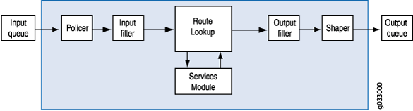
图 1 显示了基于数据包的转发的流量。
 流量
流量
当数据包进入设备时,系统会对设备应用分类器、过滤器和监管器。接下来,通过路由查找确定数据包的出口接口。找到数据包的出口接口后,将应用过滤器,并将数据包发送到出口接口,在那里排队并计划传输。
基于数据包的转发不需要有关属于给定连接的前一个或后续数据包的任何信息,并且任何允许或拒绝流量的决定都是特定于数据包的。这种架构具有大规模扩展的优势,因为它在转发数据包时不跟踪单个流量或状态。
了解基于数据包的选择性无状态服务
选择性、基于无状态数据包的服务允许您在系统上同时使用基于流和基于数据包的转发。您可以使用无状态防火墙过滤器(也称为访问控制列表 (ACL)),有选择地定向需要基于数据包的无状态转发的流量,以避免有状态的流转发。未定向的流量遵循默认的基于流的转发路径。绕过基于流的转发对于明确希望避免流会话扩展约束的流量非常有用。
默认情况下,运行 Junos OS 的瞻博网络安全性设备使用基于流的转发。选择性、基于状态数据包的服务允许您将设备配置为仅根据输入过滤器术语为所选流量提供基于数据包的处理。其他流量则用于基于流的转发。绕过基于流的转发对于希望避免会话扩展限制以及会话创建和维护成本的部署非常有用。
将设备配置为基于数据包的选择性无状态处理时,进入系统的数据包将根据特定条件进行不同的处理:
如果数据包满足输入过滤器术语中指定的匹配条件,则将其标记为数据包模式,并对其应用所有配置的数据包模式功能。未应用基于流的安全功能。它绕过了它们。
如果数据包未被标记为数据包模式,则会进行正常处理。除 MPLS 以外的所有服务都可以应用于此流量。
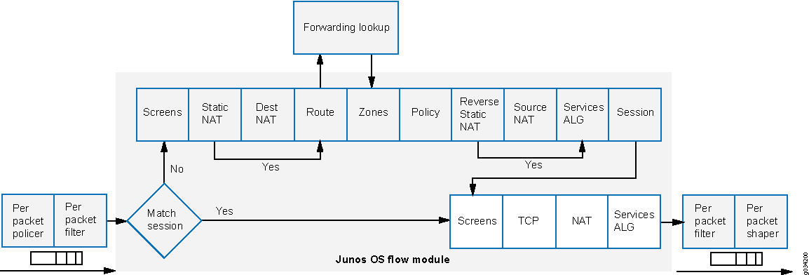
图 2 显示了绕过基于流的处理的选择性无状态数据包服务的流量流。
 的流量
的流量
当数据包进入某个接口时,将应用接口上配置的输入数据包过滤器。
如果数据包符合 防火墙过滤器中指定的条件,
packet-mode则会为数据包设置操作修饰符。数据包模式操作修饰符更新数据包密钥缓冲区中的位字段 — 此位字段用于确定是否需要绕过基于流的转发。因此,带有数据包模式操作修饰符的数据包将完全绕过基于流的转发。数据包的出口接口通过路由查找确定。找到数据包的出口接口后,将应用过滤器,并将数据包发送到出口接口,在那里排队并计划传输。如果数据包与此过滤器术语中指定的条件不匹配,则会根据过滤器中配置的其他条款对其进行评估。如果在评估完所有术语后,数据包与过滤器中的术语均不匹配,则该数据包将被静默丢弃。要防止数据包被丢弃,请在过滤器中配置一个术语,用于指定接受所有数据包的操作。
一组定义的无状态服务可与基于数据包的选择性无状态服务一起使用:
IPv4/IPv6 路由(单播和组播协议)
服务等级 (CoS)
链路分段和交织 (LFI)
通用路由封装 (GRE)
2 层交换
MPLS (MPLS)
无状态防火墙过滤器
压缩实时传输协议 (CRTP)
尽管必须在数据包模式下处理需要 MPLS 服务的流量,但在某些情况下,可能需要同时向此流量应用某些只能在流模式下提供的服务,如状态检测、NAT 和 IPsec。要指示系统以流模式和数据包模式处理流量,必须配置通过隧道接口连接的多个路由实例。必须将一个路由实例配置为在流模式下处理数据包,而另一个路由实例则必须配置为在数据包模式下处理数据包。使用隧道接口连接路由实例时,这些路由实例之间的流量将再次注入转发路径,然后可以使用不同的转发方法进行重新处理。
基于数据包的选择性无状态服务配置概述
SRX300、SRX320、SRX340、SRX345 和 vSRX 虚拟防火墙设备支持此功能。您可以使用无状态防火墙过滤器(也称为访问控制列表 (ACL))配置基于数据包的选择性无状态服务。您可以通过在防火墙过滤器中指定匹配条件来对基于数据包的转发流量进行分类,并配置操作 packet-mode 修饰符以指定操作。定义匹配条件和操作后,防火墙过滤器就会应用于相关接口。
要配置防火墙过滤器,请执行以下操作:
当数据包进入某个接口时,将应用接口上配置的输入数据包过滤器。如果数据包符合指定条件并 packet-mode 配置了操作,则数据包将完全绕过基于流的转发。
配置过滤器时,请注意防火墙过滤器中术语的顺序。按照配置中列出的顺序针对每个术语对数据包进行测试。找到第一个匹配条件后,与该术语关联的操作将应用于数据包,并且防火墙过滤器的评估将 next term 结束,除非包含操作修饰符。如果包含该 next term 操作,则根据防火墙过滤器中的下一个术语评估匹配的数据包;否则,不会根据防火墙过滤器中的后续术语评估匹配的数据包。
为基于数据包的选择性无状态服务配置防火墙过滤器时:
准确识别需要绕过流的流量,以避免不必要的数据包丢弃。
确保对基于数据包的流路径中涉及的所有接口应用带有数据包模式操作的防火墙过滤器。
确保将主机绑定的 TCP 流量配置为使用基于流的转发 — 在为包含操作修饰符的
packet-mode防火墙过滤器术语指定匹配条件时,排除此流量。配置为绕过流的任何主机绑定 TCP 流量都将被丢弃。基于数据包的选择性无状态服务不支持异步流模式处理。使用
packet-mode操作修饰符配置输入数据包过滤器(非输出)。
基于数据包的选择性无状态服务不支持嵌套防火墙过滤器(在另一个过滤器的期限内配置过滤器)。
您可以在一些典型部署方案中配置基于数据包的选择性无状态服务:
专用 LAN 和 WAN 接口之间的流量流,例如内网流量,其中端到端转发是基于数据包的
专用 LAN 接口和不太安全的 WAN 接口之间的流量流动,其中流量分别使用基于数据包和基于流的转发来实现安全和不太安全的流量
专用 LAN 和 WAN 接口之间的流量,当专用 WAN 链路关闭时,可故障切换到基于流的 IPsec WAN
流量从基于流的 LAN 流向基于数据包的 MPLS WAN
示例:为基于数据包的端到端转发配置选择性无状态数据包服务
此示例说明如何为基于数据包的端到端转发配置有选择性的无状态数据包服务。SRX300、SRX320、SRX340、SRX345 和 vSRX 虚拟防火墙设备支持此功能
要求
开始之前:
-
了解如何配置无状态防火墙过滤器。
-
建立基本连接。.
概述
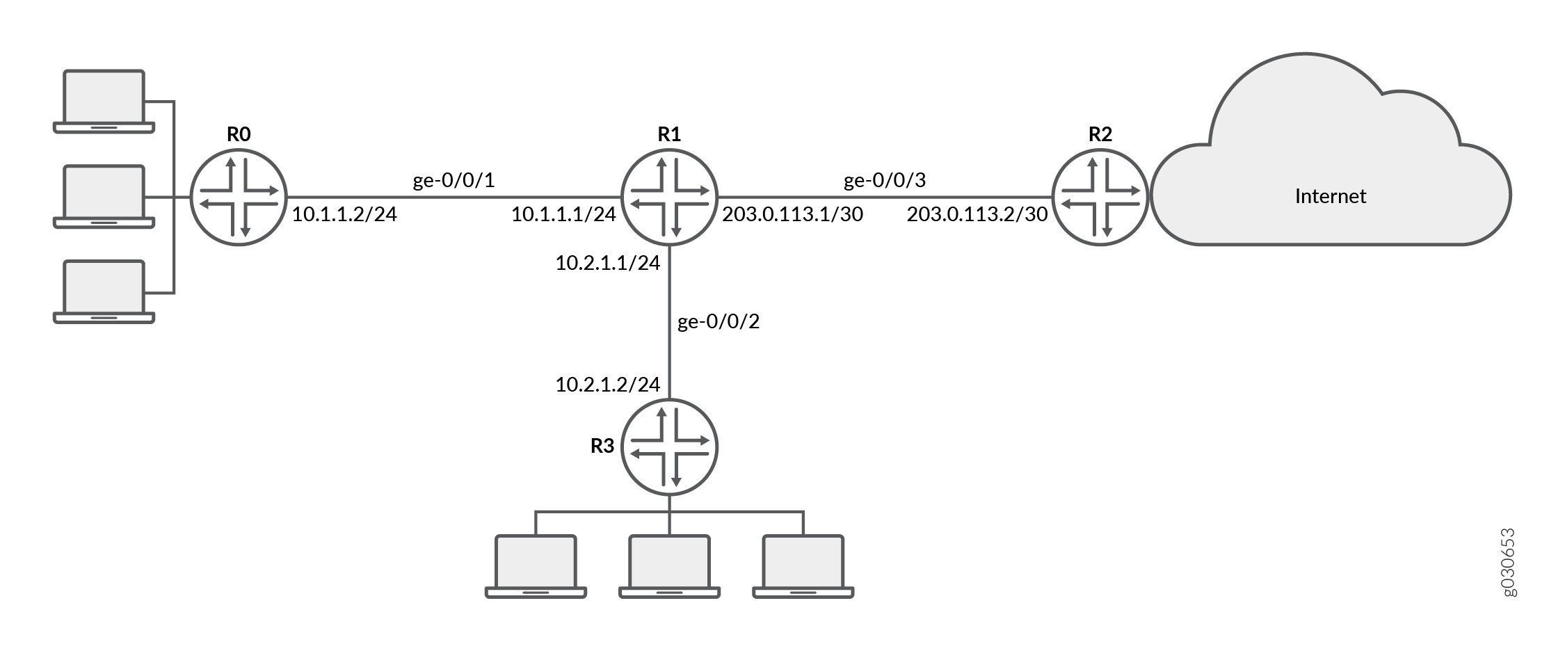
在此示例中,您将为每个设备上的接口配置 IP 地址。对于 R0,它是 10.1.1.2/24 ;对于 R1,它们是 10.1.1.1/24、10.2.1.1/24 和 203.0.113.1/30;对于 R2,它是 203.0.113.2/30;对于 R3,它是 10.2.1.2/24。您可以创建静态路由并为设备关联下一跃点地址,如下所示:R0 为 10.1.1.2,R1 为 198.51.100.2,R2 为 203.0.113.1,R3 为 10.2.1.1。
然后在设备 R1 上配置一个名为 untrust 的区域,并将其分配给接口 ge-0/0/3。您还可以创建一个名为 trust 的区域,并为其分配接口 ge-0/0/1 和 ge-0/0/2。您可以配置信任和非信任区域,以允许所有受支持的应用程序服务作为入站服务。您允许来自任何源地址、目标地址和应用的流量在区域之间传递。
然后,您可以创建防火墙过滤器 bypass-flow-filter,并定义术语 bypass-flow-term-1 和 bypass-flow-term-2,用于匹配内部接口 ge-0/0/1 和 ge-0/0/2 之间的流量,并包含数据包模式操作修饰符。您定义术语 accept-rest 以接受所有剩余流量。最后,将防火墙过滤器 bypass-flow-filter 应用于内部接口 ge-0/0/1 和 ge-0/0/2(不在外部接口上)。因此,所有内部流量都会绕过基于流的转发,而进出互联网的流量也不会绕过基于流的转发。
图 3 显示了此示例中使用的网络拓扑。
 的内部网流量
贵公司的分支机构通过专用 WAN 相互连接。对于此类内部流量,需要数据包转发,因为安全性不是问题。因此,对于此流量,您决定配置基于数据包的选择性无状态服务,以绕过基于流的转发。进出互联网的其余流量使用基于流的转发。
配置
过程
CLI 快速配置
要快速配置此示例,请复制以下命令,将其粘贴到文本文件中,删除所有换行符,更改详细信息,以便与网络配置匹配,然后将命令复制并粘贴到层次结构级别的 [edit] CLI 中,然后从配置模式进入。commit
{device R0}
[edit]
set interfaces ge-0/0/1 description "Internal 1" unit 0 family inet address 10.1.1.2/24
set routing-options static route 0.0.0.0/0 next-hop 10.1.1.1
{device R1}
set interfaces ge-0/0/1 description "Internal 1" unit 0 family inet address 10.1.1.1/24
set interfaces ge-0/0/2 description "Internal 2" unit 0 family inet address 10.2.1.1/24
set interfaces ge-0/0/3 description "Internet" unit 0 family inet address 203.0.113.1/30
set routing-options static route 0.0.0.0/0 next-hop 203.0.113.2
set security zones security-zone untrust interfaces ge-0/0/3
set security zones security-zone trust interfaces ge-0/0/1
set security zones security-zone trust interfaces ge-0/0/2
set security zones security-zone trust host-inbound-traffic system-services all
set security zones security-zone untrust host-inbound-traffic system-services all
set security policies from-zone trust to-zone untrust policy Internet-traffic match source-address any destination-address any application any
set security policies from-zone trust to-zone untrust policy Internet-traffic then permit
set security policies from-zone untrust to-zone trust policy Incoming-traffic match source-address any destination-address any application any
set security policies from-zone untrust to-zone trust policy Incoming-traffic then permit
set security policies from-zone trust to-zone trust policy Intrazone-traffic match source-address any destination-address any application any
set security policies from-zone trust to-zone trust policy Intrazone-traffic then permit
set firewall family inet filter bypass-flow-filter term bypass-flow-term-1 from source-address 10.1.1.0/24
set firewall family inet filter bypass-flow-filter term bypass-flow-term–1 from destination-address 10.2.1.0/24
set firewall family inet filter bypass-flow-filter term bypass-flow-term-1 then packet-mode
set firewall family inet filter bypass-flow-filter term bypass-flow-term-2 from source-address 10.2.1.0/24
set firewall family inet filter bypass-flow-filter term bypass-flow-term-2 from destination-address 10.1.1.0/24
set firewall family inet filter bypass-flow-filter term bypass-flow-term-2 then packet-mode
set firewall family inet filter bypass-flow-filter term accept-rest then accept
set interfaces ge-0/0/1 description "Internal 1" unit 0 family inet filter input bypass-flow-filer
set interfaces ge-0/0/2 description "Internal 2" unit 0 family inet filter input bypass-flow-filer
{device R2}
set interfaces ge-0/0/3 description "Internet" unit 0 family inet address 10.1.1.2/30
set routing-options static route 0.0.0.0/0 next-hop 10.1.1.1
{device R3}
[edit]
set interfaces ge-0/0/2 description "Internal 2" unit 0 family inet address 10.2.1.2/24
set routing-options static route 0.0.0.0/0 next-hop 10.2.1.1
分步程序
下面的示例要求您在各个配置层级中进行导航。有关如何执行此操作的说明,请参阅《CLI 用户指南》中的在配置模式下使用 CLI 编辑器。
要为基于数据包的端到端转发配置选择性的无状态数据包服务:
-
配置设备 R0、R1、R2 和 R3 上接口的 IP 地址。
{device R0} [edit] user@host#set interfaces ge-0/0/1 description "Internal 1" unit 0 family inet address 10.1.1.2/24{device R1} [edit] user@host#set interfaces ge-0/0/1 description "Internal 1" unit 0 family inet address 10.1.1.1/24user@host#set interfaces ge-0/0/2 description "Internal 2" unit 0 family inet address 10.2.1.1/24user@host#set interfaces ge-0/0/3 description "Internet" unit 0 family inet address 203.0.113.1/30{device R2} [edit] user@host#set interfaces ge-0/0/3 description "Internet" unit 0 family inet address 203.0.113.1/30{device R3} [edit] user@host#set interfaces ge-0/0/2 description "Internal 2" unit 0 family inet address 10.2.1.2/24 -
创建静态路由,并为设备 R0、R1、R2 和 R3 关联相应的下一跃点地址。
{device R0} [edit] user@host#set routing-options static route 0.0.0.0/0 next-hop 10.1.1.1{device R1} [edit] user@host#set routing-options static route 0.0.0.0/0 next-hop 203.0.113.1{device R2} [edit] user@host#set routing-options static route 0.0.0.0/0 next-hop 203.0.113.2{device R3} [edit] user@host#set routing-options static route 0.0.0.0/0 next-hop 10.2.1.1 -
配置安全区域并分配接口。
{device R1} [edit] user@host#set security zones security-zone untrust interfaces ge-0/0/3user@host#set security zones security-zone trust interfaces ge-0/0/1user@host#set security zones security-zone trust interfaces ge-0/0/2 -
为区域配置应用服务。
{device R1} [edit] user@host#set security zones security-zone trust host-inbound-traffic system-services alluser@host#set security zones security-zone untrust host-inbound-traffic system-services all -
配置安全策略
{device R1} [edit] user@host#set security policies from-zone trust to-zone untrust policy Internet-traffic match source-address any destination-address any application anyuser@host#set security policies from-zone trust to-zone untrust policy Internet-traffic then permituser@host#set security policies from-zone untrust to-zone trust policy Incoming-traffic match source-address any destination-address any application anyuser@host#set security policies from-zone untrust to-zone trust policy Incoming-traffic then permituser@host#set security policies from-zone trust to-zone trust policy Intrazone-traffic match source-address any destination-address any application anyuser@host#set security policies from-zone trust to-zone trust policy Intrazone-traffic then permit -
创建防火墙过滤器,并为所有基于数据包的转发流量定义术语。
{device R1} [edit] user@host#set firewall family inet filter bypass-flow-filter term bypass-flow-term-1 from source-address 10.1.1.0/24user@host#set firewall family inet filter bypass-flow-filter term bypass-flow-term–1 from destination-address 10.2.1.0/24user@host#set firewall family inet filter bypass-flow-filter term bypass-flow-term-1 then packet-modeuser@host#set firewall family inet filter bypass-flow-filter term bypass-flow-term-2 from source-address 10.2.1.0/24user@host#set firewall family inet filter bypass-flow-filter term bypass-flow-term-2 from destination-address 10.1.1.0/24user@host#set firewall family inet filter bypass-flow-filter term bypass-flow-term-2 then packet-mode -
为剩余流量指定另一个术语。
{device R1} [edit] user@host#set firewall family inet filter bypass-flow-filter term accept-rest then accept -
将防火墙过滤器应用于相关接口。
{device R1} [edit] user@host#set interfaces ge-0/0/1 description "Internal 1" unit 0 family inet filter input bypass-flow-fileruser@host#set interfaces ge-0/0/2 description "Internal 2" unit 0 family inet filter input bypass-flow-filer
结果
在配置模式下,输入 show interfaces、 show routing-options和 show firewall 命令以确认您的配置。如果输出未显示预期的配置,请重复此示例中的配置说明进行更正。
{device R0}
[edit]
user@host# show interfaces
ge-0/0/1 {
    description “Internal 1”
    unit 0 {
        family inet {
            address 10.1.1.2/24
        }
    }
}
{device R0}
[edit]
user@host# show routing-options
static {
    route 0.0.0.0/0 next-hop 10.1.1.1;
}
{device R2}
[edit]
user@host# show interfaces
ge-0/0/3 {
    description “Internet”
    unit 0 {
        family inet {
            address 203.0.113.2/30;
        }
    }
}
{device R2}
[edit]
user@host# show routing-options
static {
    route 0.0.0.0/0 next-hop 203.0.113.1;
}
{device R3}
[edit]
user@host# show interfaces
ge-0/0/2 {
    description “Internal 2”
    unit 0 {
        family inet {
            address 10.2.1.2/24;
        }
    }
}
{device R3}
user@host# show routing-options
static {
    route 0.0.0.0/0 next-hop 10.2.1.1;
}
{device R1}
[edit]
user@host# show interfaces
ge-0/0/1 {
    description “internal 1”
    unit 0 {
        family inet {
            filter {
                input bypass-flow-filter;
                }
            address 10.1.1.1/24;
        }
    }
}
ge-0/0/2 {
    description “Internal 2”
    unit 0 {
        family inet {
            filter {
                input bypass-flow-filter;
                }
            address 10.2.1.1/24;
        }
    }
}
ge-0/0/3 {
    description “Internet”
    unit 0 {
        family inet {
            address 203.0.113.1/30;
        }
    }
}
{device R1}
[edit]
user@host# show routing-options
static {
    route 0.0.0.0/0 next-hop 203.0.113.1;
}
{device R1}
[edit]
user@host# show firewall
family inet {
    filter bypass-flow-filter {
        term bypass-flow-term-1 {
            from {
                source-address {
                    10.1.1.0/24;
                }
                destination-address {
                    10.2.1.0/24;
                }
            }
            then packet-mode;
        }
        term bypass-flow-term-2 {
            from {
                source-address {
                    10.2.1.0/24;
                }
                destination-address {
                    10.1.1.0/24;
                }
            }
            then packet-mode;
        }
        term accept-rest {
            then accept;
        }
    }
}
如果完成设备配置,请从配置模式进入。commit
验证
确认配置工作正常。
验证基于数据包的端到端配置
目的
验证是否配置了基于数据包的选择性无状态服务。
行动
从配置模式,输入 show interfaces、 show routing-options、 show security zones和 show security policies命令 show firewall 。
验证输出是否显示防火墙过滤器、接口和策略的预期配置。
验证是否按要测试数据包的顺序列出术语。您可以使用命令 insert 在防火墙过滤器中移动术语。
验证 Intranet 流量上的会话建立
目的
验证将流量传输到 Intranet 内的接口时是否已建立会话。
行动
要验证会话是否已建立,请执行以下任务:
-
在设备上
R1,输入操作模式clear security flow session all命令以清除所有现有的安全流会话。 -
在设备上
R0,输入操作模式ping命令以将流量传输到设备R3。 -
在设备上
R1,当流量从设备R0传输到R3通过R1时,输入操作模式show security flow session命令。Flow Sessions on FPC10 PIC1: Total sessions: 0 Flow Sessions on FPC10 PIC2: Total sessions: 0 Flow Sessions on FPC10 PIC3: Total sessions: 0
要验证已建立的会话,请确保在命令发送和接收数据包时ping输入show security flow session命令。
{device R0}
user@host> ping 203.0.113.6
PING 203.0.113.6 (203.0.113.6): 56 data bytes 64 bytes from 203.0.113.6: icmp_seq=0 ttl=63 time=2.326 ms 64 bytes from 203.0.113.6: icmp_seq=1 ttl=63 time=2.569 ms 64 bytes from 203.0.113.6: icmp_seq=2 ttl=63 time=2.565 ms 64 bytes from 203.0.113.6: icmp_seq=3 ttl=63 time=2.563 ms 64 bytes from 203.0.113.6: icmp_seq=4 ttl=63 time=2.306 ms 64 bytes from 203.0.113.6: icmp_seq=5 ttl=63 time=2.560 ms 64 bytes from 203.0.113.6: icmp_seq=6 ttl=63 time=4.130 ms 64 bytes from 203.0.113.6: icmp_seq=7 ttl=63 time=2.316 ms ...
{device R1}
user@host> show security flow session
Flow Sessions on FPC10 PIC1:
Total sessions: 0

Flow Sessions on FPC10 PIC2:
Total sessions: 0

Flow Sessions on FPC10 PIC3:
Total sessions: 0
输出显示流量正在从传输到R0R3未建立任何会话。在此示例中,您对接口Internal 1和Internal 2公司的 Intranet 流量应用了 with bypass-flow-filter packet-mode 操作修饰符。此输出验证两个接口之间的流量是否正确绕过基于流的转发,因此未建立任何会话。
验证互联网流量上的会话建立
目的
验证在将流量传输到互联网时是否已建立会话。
行动
要验证流向互联网的流量是否使用基于流的转发以及是否已建立会话,请执行以下操作:
-
在设备上
R1,输入操作模式clear security flow session all命令以清除所有现有的安全流会话。 -
在设备上
R0,输入操作模式ping命令以将流量传输到设备R2。 -
在设备上
R1,当流量从传输到R0R2通过R1时,输入操作模式show security flow session命令。
要验证已建立的会话,请确保在命令发送和接收数据包时ping输入show security flow session命令。
{device R0}
user@host> ping 10.2.1.2 -c 10
PING 10.2.1.2 (10.2.1.2) 56(84) bytes of data. 64 bytes from 10.2.1.2: icmp_seq=1 ttl=63 time=6.07 ms 64 bytes from 10.2.1.2: icmp_seq=2 ttl=63 time=4.24 ms 64 bytes from 10.2.1.2: icmp_seq=3 ttl=63 time=2.85 ms 64 bytes from 10.2.1.2: icmp_seq=4 ttl=63 time=6.14 ms ...
{device R1}
user@host>show security flow session
Flow Sessions on FPC10 PIC1: Session ID: 410000077, Policy name: Internet-traffic/5, Timeout: 2, Valid In: 10.1.1.2/3 --> 10.2.1.2/32055;icmp, If: ge-0/0/1.0, Pkts: 1, Bytes: 84, CP Session ID: 410000198 Out: 10.2.1.2/32055 --> 10.1.1.2/3;icmp, If: ge-0/0/2.0, Pkts: 1, Bytes: 84, CP Session ID: 410000198 Total sessions: 1 Flow Sessions on FPC10 PIC2: Session ID: 420000079, Policy name: Internet-traffic/5, Timeout: 2, Valid In: 10.1.1.2/5 --> 10.2.1.2/32055;icmp, If: ge-0/0/1.0, Pkts: 1, Bytes: 84, CP Session ID: 420000163 Out: 10.2.1.2/32055 --> 10.1.1.2/5;icmp, If: ge-0/0/2.0, Pkts: 1, Bytes: 84, CP Session ID: 420000163 Total sessions: 1 Flow Sessions on FPC10 PIC3: Session ID: 430000090, Policy name: Internet-traffic/5, Timeout: 4, Valid In:10.1.1.2/7 --> 10.2.1.2/32055;icmp, If: ge-0/0/1.0, Pkts: 1, Bytes: 84, CP Session ID: 430000088 Out: 10.2.1.2/32055 --> 10.1.1.2/7;icmp, If: ge-0/0/2.0, Pkts: 1, Bytes: 84, CP Session ID: 430000088 Total sessions: 1
输出显示从设备R0传输到R1已建立会话的流量。在此示例中,您未对公司的互联网流量应用bypass-flow-filterpacket-mode接口上的Internet操作修饰符。此输出验证流向互联网的流量是否正确使用了基于流的转发,从而建立会话。
将流量从设备 R3 传输到 R2 ,并使用本部分中的命令验证已建立的会话。
示例:为基于数据包到基于流的转发配置选择性无状态数据包服务
此示例说明如何为基于数据包到基于流的转发配置选择性无状态数据包服务。SRX300、SRX320、SRX340、SRX345 和 vSRX 虚拟防火墙设备支持此功能。
要求
开始之前:
-
了解如何配置无状态防火墙过滤器。
-
建立基本连接。.
概述
在此示例中,您将为每个设备上的接口配置 IP 地址。设备 R0 为 198.51.100.9/24;对于 R1,是 198.51.100.10/24 和 203.0.113.5/24;对于 R2,它是 203.0.113.9/24。在设备 R1 上,您可以在路由实例之间设置内部服务接口 lt-0/0/0,并在两个虚拟设备之间配置对等关系。然后,您可以创建两个安全区域:Primary-VR-zone 和 Internet-VR-zone,为其分配相关接口,并对其进行配置以允许所有受支持的应用和协议。
然后,配置策略并指定允许所有数据包。您可以配置虚拟设备路由实例 Internet-VR,并为基于流的转发分配接口。在设备 R0、R1 和 R2 上启用 OSPF。在设备 R2 上,使用包含数据包模式操作修饰符的术语 bypass-flow-term 配置过滤器 bypass-flow-filter。由于您尚未指定任何匹配条件,因此此过滤器适用于遍历应用该过滤器的接口的所有流量。
最后,在设备 R1 上,将防火墙过滤器 bypass-flow-filter 应用于内部接口 ge-0/0/2.0 和 lt-0/0/0.0。您不会将过滤器应用于与 Internet-VR 路由实例关联的接口。因此,遍历与主路由实例关联的 LAN 接口的所有流量都使用基于数据包的转发,而遍历 Internet-VR 路由实例的所有流量都使用基于流的转发。
图 4 显示了此示例中使用的网络拓扑。
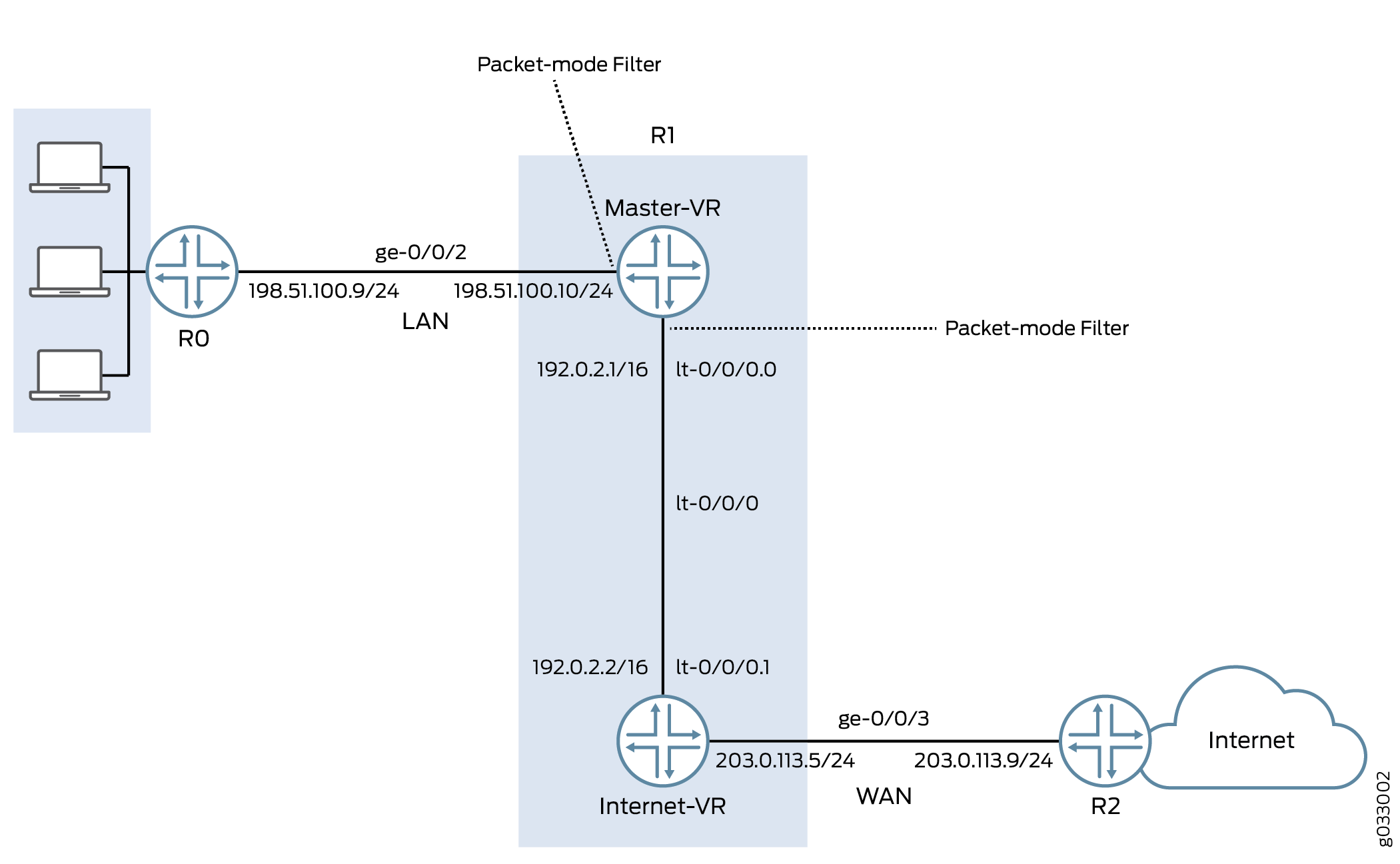
面向专用 LAN 的接口不需要任何安全服务,但面向 WAN 的接口需要安全服务。在此示例中,您决定通过配置两个路由实例(一个处理基于数据包的转发,另一个处理基于流的转发)来为安全但不太安全的流量配置基于数据包和基于流的转发。
配置
过程
CLI 快速配置
要快速配置此示例,请复制以下命令,将其粘贴到文本文件中,删除所有换行符,更改详细信息,以便与网络配置匹配,然后将命令复制并粘贴到层次结构级别的 [edit] CLI 中,然后从配置模式进入。commit
{device R0}
set interfaces description “Connect to Primary VR” ge-0/0/2 unit 0 family inet address 198.51.100.9/24
set protocols ospf area 0.0.0.0 interface ge-0/0/2.0
{device R1}
set interfaces description “Connect to R0” ge-0/0/2 unit 0 family inet address 198.51.100.10/24
set interfaces description “Connect to R2” ge-0/0/3 unit 0 family inet address 203.0.113.5/24
set interfaces lt-0/0/0 unit 0 encapsulation frame-relay dlci 100 peer-unit 1 family inet address 192.0.2.1/16
set interfaces lt-0/0/0 unit 1 encapsulation frame-relay dlci 100 peer-unit 0 family inet address 192.0.2.2/16
set security zones security-zone Primary-VR-zone host-inbound-traffic system-services all
set security zones security-zone Primary-VR-zone host-inbound-traffic protocols all
set security zones security-zone Primary-VR-zone interfaces ge-0/0/2.0
set security zones security-zone Primary-VR-zone interfaces lt-0/0/0.0
set security zones security-zone Internet-VR-zone host-inbound-traffic system-services all
set security zones security-zone Internet-VR-zone host-inbound-traffic protocols all
set security zones security-zone Internet-VR-zone interfaces ge-0/0/3.0
set security zones security-zone Internet-VR-zone interfaces lt-0/0/0.1
set security policies default-policy permit-all
set routing-instances Internet-VR instance-type virtual-router interface lt-0/0/0.1
set routing-instances Internet-VR instance-type virtual-router interface ge-0/0/3.0
set protocols ospf area 0.0.0.0 interface ge-0/0/2.0
set protocols ospf area 0.0.0.0 interface lt-0/0/0.0
set routing-instances Internet-VR protocols ospf area 0.0.0.0 interface lt-0/0/0.1
set routing-instances Internet-VR protocols ospf area 0.0.0.0 interface ge-0/0/3.0
set firewall family inet filter bypass-flow-filter term bypass-flow-term then accept
set firewall family inet filter bypass-flow-filter term bypass-flow-term then packet-mode
set interfaces ge-0/0/2 unit 0 family inet filter input bypass-flow-filter
set interfaces lt-0/0/0 unit 0 family inet filter input bypass-flow-filter
{device R2}
set interfaces description “Connect to Internet-VR” ge-0/0/3 unit 0 family inet address 203.0.113.9/24
set protocols ospf area 0.0.0.0 interface ge-0/0/3
分步程序
下面的示例要求您在各个配置层级中进行导航。有关如何执行此操作的说明,请参阅《CLI 用户指南》中的在配置模式下使用 CLI 编辑器。
要为基于数据包的端到端转发配置选择性的无状态数据包服务:
-
配置接口的 IP 地址。
{device R0} [edit] user@host#set interfaces description “Connect to Primary VR” ge-0/0/2 unit 0 family inet address 198.51.100.9/24{device R1} [edit] user@host#set interfaces description “Connect to R0” ge-0/0/2 unit 0 family inet address 198.51.100.10/24user@host#set interfaces description “Connect to R2” ge-0/0/3 unit 0 family inet address 203.0.113.5/24{device R2} [edit] user@host#set interfaces description “Connect to Internet-VR” ge-0/0/3 unit 0 family inet address 203.0.113.9/24 -
在路由实例之间设置内部服务接口。
{device R1} [edit] user@host#set interfaces lt-0/0/0 unit 0 encapsulation frame-relay dlci 100 peer-unit 1 family inet address 192.0.2.1/16user@host#set interfaces lt-0/0/0 unit 1 encapsulation frame-relay dlci 100 peer-unit 0 family inet address 192.0.2.2/16 -
配置安全区域。
{device R1} [edit] user@host#set security zones security-zone Primary-VR-zone host-inbound-traffic system-services alluser@host#set security zones security-zone Primary-VR-zone host-inbound-traffic protocols alluser@host#set security zones security-zone Primary-VR-zone interfaces ge-0/0/2.0user@host#set security zones security-zone Primary-VR-zone interfaces lt-0/0/0.0user@host#set security zones security-zone Internet-VR-zone host-inbound-traffic system-services alluser@host#set security zones security-zone Internet-VR-zone host-inbound-traffic protocols alluser@host#set security zones security-zone Internet-VR-zone interfaces ge-0/0/3.0user@host#set security zones security-zone Internet-VR-zone interfaces lt-0/0/0.1 -
配置策略。
{device R1} [edit] user@host#set security policies default-policy permit-all -
配置虚拟设备路由实例。
{device R1} [edit] user@host#set routing-instances Internet-VR instance-type virtual-router interface lt-0/0/0.1user@host#set routing-instances Internet-VR instance-type virtual-router interface ge-0/0/3.0 -
在网络中的所有接口上启用 OSPF。
{device R0} [edit] user@host#set protocols ospf area 0.0.0.0 interface ge-0/0/2.0{device R1 for Primary-VR} [edit] user@host#set protocols ospf area 0.0.0.0 interface ge-0/0/2.0user@host#set protocols ospf area 0.0.0.0 interface lt-0/0/0.0{device R1 for Internet-VR} [edit] user@host#set routing-instances Internet-VR protocols ospf area 0.0.0.0 interface lt-0/0/0.1user@host#set routing-instances Internet-VR protocols ospf area 0.0.0.0 interface ge-0/0/3.0{device R2} [edit] user@host#set protocols ospf area 0.0.0.0 interface ge-0/0/3 -
创建防火墙过滤器并定义基于数据包的转发流量术语。
{device R1} [edit] user@host#set firewall family inet filter bypass-flow-filter term bypass-flow-term then acceptuser@host#set firewall family inet filter bypass-flow-filter term bypass-flow-term then packet-mode -
将防火墙过滤器应用于相关接口。
{device R1} [edit] user@host#set interfaces ge-0/0/2 unit 0 family inet filter input bypass-flow-filteruser@host#set interfaces lt-0/0/0 unit 0 family inet filter input bypass-flow-filter
结果
在配置模式下,输入 show interfaces、 show protocols、 show routing-instancesshow security和show firewall命令以确认您的配置。如果输出未显示预期的配置,请重复此示例中的配置说明进行更正。
{device R0}
[edit]
user@host# show interfaces
ge-0/0/2 {
description “Connect to Primary-VR”
unit 0 {
family inet {
address 198.51.100.9/24
}
}
}
{device R0}
[edit]
user@host# show protocols
ospf {
area 0.0.0.0/0 {
interface ge-0/0/2.0;
}
}
{device R2}
[edit]
user@host# show interfaces
ge-0/0/3 {
description “Connect to Internet-VR”
unit 0 {
family inet {
address 203.0.113.9/24;
}
}
}
{device R2}
[edit]
user@host# show protocols
ospf {
area 0.0.0.0/0 {
interface ge-0/0/3.0;
}
}
{device R1}
[edit]
user@host# show interfaces
ge-0/0/2 {
description “Connect to R0”
unit 0 {
family inet {
filter {
input bypass-flow-filter;
}
address 198.51.100.10/24;
}
}
}
lt-0/0/0 {
unit 0 {
encapsulation frame-relay;
dlci 100;
peer-unit 1;
family inet {
filter {
input bypass-flow-filter
}
address 192.0.2.1/16;
}
}
unit 1{
encapsulation frame-relay;
dlci 100;
peer-unit 0;
family inet {
address 192.0.2.2/16 ;
}
}
}
{device R1}
[edit]
user@host# show protocols
ospf {
area 0.0.0.0/0 {
interface ge-0/0/2.0;
interface lt-0/0/0.0;
}
}
{device R1}
[edit]
user@host# show firewall
filter bypass-flow-filter {
term bypass-flow-term {
then {
packet-mode;
accept;
}
}
}
{device R1}
[edit]
user@host# show routing-instances
Internet-VR {
instance-type virtual-router;
interface lt-0/0/0.1;
interface ge-0/0/3.0;
protocols {
ospf {
area 0.0.0.0 {
interface ge-0/0/3.0;
lt-0/0/0.1;
}
}
}
}
{device R1}
[edit]
user@host# show security
security zone Primary-VR-zone {
host-inbound-traffic {
system-services {
all;
{
protocols {
all;
{
{
intefaces {
ge-0/0/2.0;
lt-0/0/0.0;
{
{
security zone Internet-VR-zone {
host-inbound-traffic {
system-services {
all;
{
protocols {
all;
}
}
intefaces {
ge-0/0/3.0;
lt-0/0/0.1;
{
{
policies {
default-policy {
permit-all;
}
}
如果完成设备配置,请从配置模式进入。commit
验证
确认配置工作正常。
验证基于数据包到基于流的配置
目的
验证是否已针对基于数据包到基于流的转发配置了选择性无状态数据包服务。
行动
从配置模式,输入 show interfaces、 show protocols、 show security和 show routing-instances命令 show firewall 。
验证输出是否显示了防火墙过滤器、路由实例、接口和策略的预期配置。
验证是否按要测试数据包的顺序列出术语。您可以使用命令 insert 在防火墙过滤器中移动术语。
验证 LAN 流量上的会话建立
目的
验证在 LAN 内的接口上传输流量时是否已建立会话。
行动
要验证会话是否已建立,请执行以下任务:
-
在设备上
R1,在操作模式下输入命令clear security flow session all以清除所有现有安全流会话。 -
在设备上
R0,在操作模式下输入命令ping以将流量传输到设备Primary-VR。 -
在设备上
R1,当流量从设备R0R1通过 传输时,从操作模式下输入show security flow session命令。
要验证已建立的会话,请确保在命令发送和接收数据包时ping输入命令show security flow session。
{device R0}
user@host> ping 192.0.2.1
PING 192.0.2.1 (192.0.2.1): 56 data bytes 64 bytes from 192.0.2.1: icmp_seq=0 ttl=63 time=2.208 ms 64 bytes from 192.0.2.1: icmp_seq=1 ttl=63 time=2.568 ms 64 bytes from 192.0.2.1: icmp_seq=2 ttl=63 time=2.573 ms 64 bytes from 192.0.2.1: icmp_seq=3 ttl=63 time=2.310 ms 64 bytes from 192.0.2.1: icmp_seq=4 ttl=63 time=1.566 ms 64 bytes from 192.0.2.1: icmp_seq=5 ttl=63 time=1.569 ms ...
{device R1}
user@host> show security flow session
0 sessions displayed
输出显示流量正在从传输到R0Primary-VR未建立任何会话。在此示例中,您对接口ge-0/0/0和lt-0/0/0.0公司的 LAN 流量应用了 with bypass-flow-filter packet-mode 操作修饰符。此输出验证两个接口之间的流量是否正确绕过基于流的转发,因此未建立任何会话。
验证互联网流量上的会话建立
目的
验证在将流量传输到互联网时是否已建立会话。
行动
要验证流向互联网的流量是否使用基于流的转发以及是否已建立会话,请执行以下操作:
-
在设备上
R1,在操作模式下输入命令clear security flow session all以清除所有现有安全流会话。 -
在设备上
R0,在操作模式下输入命令ping以将流量传输到设备R2。 -
在设备
R1上,当流量从以下位置传输到R0R2通过R1时,从操作模式输入show security flow session命令。root@host> show security flow session Flow Sessions on FPC10 PIC1: Total sessions: 0 Flow Sessions on FPC10 PIC2: Total sessions: 0 Flow Sessions on FPC10 PIC3: Total sessions: 0
要验证已建立的会话,请确保在命令发送和接收数据包时ping输入命令show security flow session。
{device R0}
user@host> ping 192.0.2.1 -c 10
PING 60.0.0.1 (60.0.0.1) 56(84) bytes of data. 64 bytes from 192.0.2.1: icmp_seq=1 ttl=64 time=1.98 ms 64 bytes from 192.0.2.1: icmp_seq=2 ttl=64 time=1.94 ms 64 bytes from 192.0.2.1: icmp_seq=3 ttl=64 time=1.92 ms 64 bytes from 192.0.2.1: icmp_seq=4 ttl=64 time=1.89 ms ...
{device R1}
user@host> show security flow session
Session ID: 189900, Policy name: default-policy/2, Timeout: 2
  In: 198.51.100.9/0 --> 192.0.2.1/5924;icmp, If: lt-0/0/0.1
  Out: 192.0.2.1/5924 --> 198.51.100.9/0;icmp, If: ge-0/0/3.0

Session ID: 189901, Policy name: default-policy/2, Timeout: 2
  In: 198.51.100.9/1 --> 192.0.2.1/5924;icmp, If: lt-0/0/0.1
  Out: 192.0.2.1/5924 --> 198.51.100.9/1;icmp, If: ge-0/0/3.0

Session ID: 189902, Policy name: default-policy/2, Timeout: 4
  In: 198.51.100.9/2 --> 192.0.2.1/5924;icmp, If: lt-0/0/0.1
  Out: 192.0.2.1/5924 --> 198.51.100.9/2;icmp, If: ge-0/0/3.0

 3 sessions displayed
输出显示从设备 R0 传输到 R2 已建立会话的流量。在此示例中,您未对公司的互联网流量应用 bypass-flow-filter packet-mode with the action 修饰符 on route instance Internet-VR 。此输出验证流向互联网的流量是否正确使用了基于流的转发,从而建立会话。
请注意,仅当流量在 和 ge-0/0/3 之间lt-0/0/0.1流动时,才会建立会话,而不是当流量在 和 lt-0/0/0.0之间ge-0/0/2流动时。
变更历史表
是否支持某项功能取决于您使用的平台和版本。使用 功能资源管理器 确定您的平台是否支持某个功能。